Flexible PCB Assembly: Design, Materials & Reliability
A practical guide for engineers designing with flex circuits — when to choose flex over rigid, bend radius rules, copper and stiffener selection, and how to prevent the failure modes that kill flexible assemblies.
Why Choose Flexible PCB: Design Advantages
Flexible circuits are chosen over rigid PCBs when a design requires 3D folding, dynamic movement, weight reduction, or elimination of connectors and wiring harnesses. A single flex circuit can replace multiple rigid boards and cables, cutting assembly labor and improving reliability through fewer interconnect points.
01.
True 3D Packaging
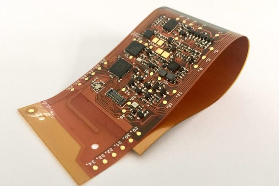
Flex circuits fold into shapes rigid boards cannot occupy — camera modules behind displays, sensor strips around catheters, hinge circuits in folding devices. Board area shrinks to the space the electronics actually need.
02.
Dynamic Motion Capability
Properly designed flex circuits with RA copper survive millions of bend cycles, connecting moving parts in robotic arms, printer heads, and wearable hinges where wires would fatigue and fail.
03.
Weight and Space Savings
Polyimide film (12.5–100µm) with etched traces weighs far less than rigid laminate and round wire harnesses — critical in aerospace and drones where every gram counts.
04.
Connector Elimination
One rigid-flex circuit replaces rigid board + cable + connector assemblies, removing three failure points per interconnect while reducing assembly cost and improving signal integrity.
Rule of thumb: choose flex when your design involves motion, folding, extreme space limits, or weight budgets. For flat, static, unconstrained designs, rigid PCBs remain more cost-effective.Lorem ipsum dolor sit amet, consectetur adipiscing elit. Ut elit tellus, luctus nec ullamcorper mattis, pulvinar dapibus leo.
Flex PCB Design Rules and Challenges
Flex circuit design is governed by bend radius rules from IPC-2223: static bends require 10× or more the circuit thickness, while dynamic flexing demands 100× or more. Copper type, trace routing in bend zones, and stiffener placement all directly determine fatigue life.
| Design Rule | Requirement | Why It Matters |
|---|---|---|
| Static Bend Radius | ≥10× circuit thickness (single/double-sided); ≥20× for multilayer | Undersized radii plastic-deform copper, starting fatigue cracks |
| Dynamic Bend Radius | ≥100× thickness for repeated flexing; RA copper mandatory | Dynamic cycling amplifies stress — ED copper cracks within thousands of cycles |
| Bend Zone Construction | No vias, pads, or traces at angles in bend zones; traces run perpendicular to bend axis; copper near neutral axis | Discontinuities and parallel-to-bend traces concentrate stress |
| Copper Foil Selection | RA (rolled-annealed) for dynamic flex; ED (electrodeposited) acceptable for static | RA copper’s grain structure survives millions of cycles vs ED’s thousands |
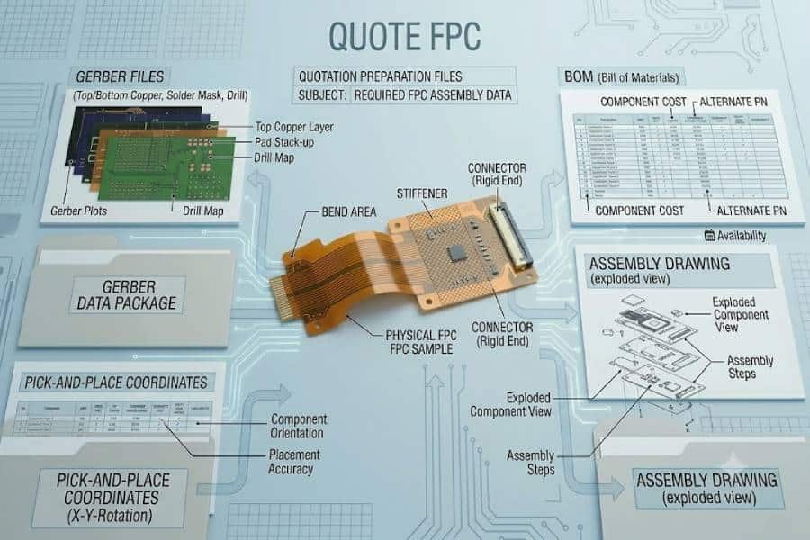
| Stiffener Planning | Define PI/FR4 stiffener zones at every component area and ZIF connector in drawings | Assembly houses cannot place components on unsupported flex |
Send flex drawings for DFM review before fabrication. Bend radius violations, missing stiffener callouts, and traces crossing bend zones at wrong angles are the top three flex design errors we see — all are free to fix on paper, expensive to discover after assembly.
Flex PCB Failure Modes: What Can Go Wrong
Most flexible circuit failures trace back to four mechanisms: copper trace fatigue cracking from undersized bend radii, pad lifting during soldering on unsupported flex, coverlay delamination from adhesive degradation, and ZIF finger wear from incorrect thickness stackup.
- Copper Trace Fatigue Cracking — Repeated bending work-hardens copper until microcracks propagate to open circuits. Root causes: bend radius below spec, ED copper in dynamic applications, traces running parallel to bend axis. Prevention: 100× radius rule + RA copper + perpendicular trace routing.
- Pad Lifting During Assembly — Soldering heat softens flex adhesive; unsupported pads lift or peel when components press down. Prevention: stiffeners under every component zone, lower-mass components on thin flex, and controlled reflow profiles.
- Coverlay Delamination — Adhesive layers degrade under thermal cycling or chemical exposure, exposing traces to abrasion and shorting. Prevention: correct coverlay pressure/temperature lamination and acrylic adhesive matched to operating temperature range.
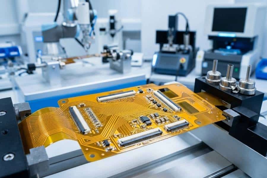
- ZIF Connector Wear & Intermittents — Flex tails thicker or thinner than 0.3mm ±0.05 tolerance cause poor contact or connector damage. Prevention: specify total stackup at gold fingers precisely — PI base + copper + coverlay + stiffener calculated together.
Specify IPC-6013 qualification and IPC-A-610 Class 3 inspection for medical or automotive flex assemblies. Require bend-zone visual inspection under magnification and electrical continuity testing on 100% of received flex assemblies.
Need Professional Flex Circuit Assembly?
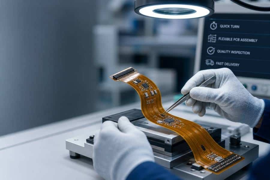
JHYPCB provides flex PCB assembly with carrier fixturing, stiffener bonding, SMT down to 0201, and 100% AOI inspection. ISO 9001 & IATF 16949 certified.
Frequently Asked Questions About Flexible PCB Assembly
Choose flex when your design involves motion (hinges, robotic joints), 3D folding into tight enclosures, strict weight limits, or connector-and-cable elimination. For flat, static designs with no space pressure, rigid PCBs remain significantly cheaper. A hybrid rigid-flex board is worth evaluating when you need rigid component zones plus flex interconnection sections.
Per IPC-2223 guidelines, static (one-time) bends require a radius of at least 10× circuit thickness for single or double-sided flex, and 20× or more for multilayer construction. Dynamic applications that flex repeatedly require 100× or more. Undersized radii permanently deform copper and initiate fatigue cracks that progress to open circuits.
Static flex is bent once during installation and stays fixed — ED copper and tighter bend radii (10×) are acceptable. Dynamic flex bends continuously in service — it requires RA (rolled-annealed) copper, 100× bend radii, uninterrupted traces running perpendicular to the bend axis, and no vias or pads in bend zones. Designing dynamic flex with static rules is the leading cause of field failures.
RA (rolled-annealed) copper has an elongated grain structure that survives millions of flex cycles — mandatory for dynamic applications. ED (electrodeposited) copper offers sharper etched traces and lower cost, suited to static installations. As a rule: any circuit that moves after installation gets RA copper; circuits bent once during assembly can use ED.
A flex PCB is entirely flexible — components must sit on stiffener-reinforced zones. A rigid-flex board combines rigid laminate sections (where components mount densely) with integrated flex sections that connect them, replacing connectors and cables entirely. Rigid-flex costs more but eliminates interconnect failures — standard in aerospace, medical probes, and compact camera modules.
Flex assembly premiums come from carrier fixtures for panel support, stiffener bonding operations, manual handling protections, and lower panel utilization versus rigid boards. The flex circuit itself also costs more per area than FR4. However, system-level cost often favors flex when it eliminates connectors, cables, and assembly labor from the product.
Ready to Start Your Flex PCB Project?
JHYPCB provides professional flex PCB assembly with carrier fixturing, stiffener bonding, and 100% AOI inspection. ISO 9001 & IATF 16949 certified.