Table of Contents
For many engineers, the first quote for a small batch of flexible PCB assembly is a shock: the unit price looks much higher than for a similar rigid FR4 board, even when the design seems simple and the quantity is low. When you are working on early prototypes or pilot builds, these “unexpected” costs can quickly consume a development budget and slow down your project schedule.
The reality is that small-batch flexible PCB assembly (FPCBA) follows a very different cost structure from standard rigid PCB assembly. Materials such as polyimide, RA copper, and coverlay are more expensive than FR4 and solder mask, and flex circuits often require extra process steps, special fixturing, and more careful handling during assembly and testing. On top of that, engineering setup, NRE, and line changeover costs are spread over only a few pieces, so they show up prominently in your unit price.
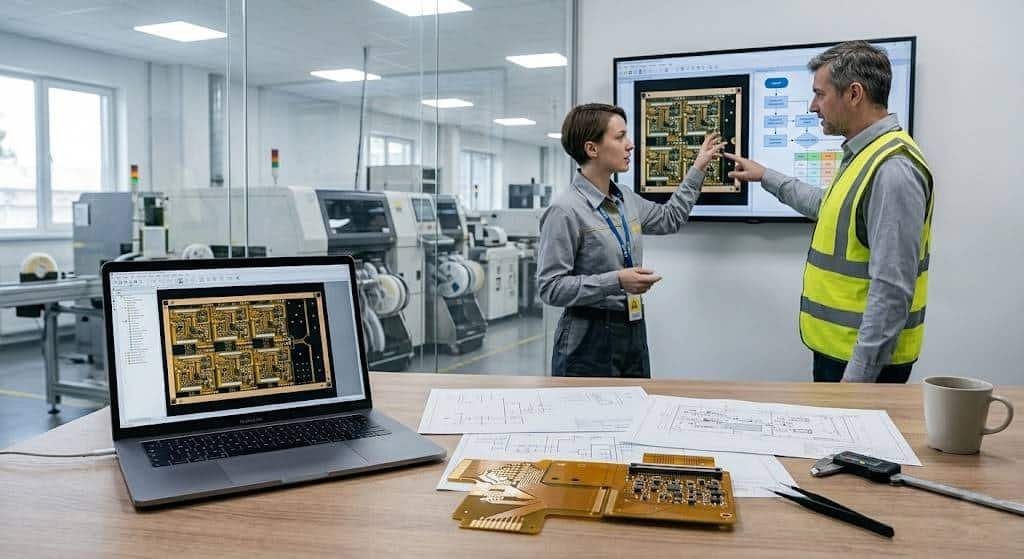
This guide is written for hardware engineers, buyers, and project managers who need transparent, engineering-level explanations of how flexible PCB assembly pricing is built up for low volumes. You will see how each cost element behaves when the order quantity is small, how design and DFM decisions directly affect your quote, and what you can realistically do to control FPCBA cost without sacrificing reliability or build quality.
By the end, you should be able to look at your own flex design and roughly predict which parts of the quote are driven by bare-board materials, which come from assembly complexity, and which are simply fixed costs being spread over a small batch. That way, instead of treating the quote as a “black box”, you can have a focused discussion with your flexible PCB assembly partner about specific changes that can bring the total cost into your target range.
Why Small-Batch Flexible PCB Assembly Seems So Expensive
Flex vs Rigid Boards: Why the Cost Structure Is Different
If you are used to ordering rigid FR4 assemblies, the first flexible PCB assembly quote almost always feels “out of proportion”. On paper the board might even look smaller and simpler than your usual designs, yet the total price and the per‑unit cost both jump. The main reason is that a flex circuit is built on a different stack of materials and goes through more specialized processes than a standard rigid board.
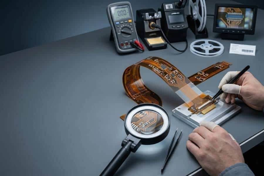
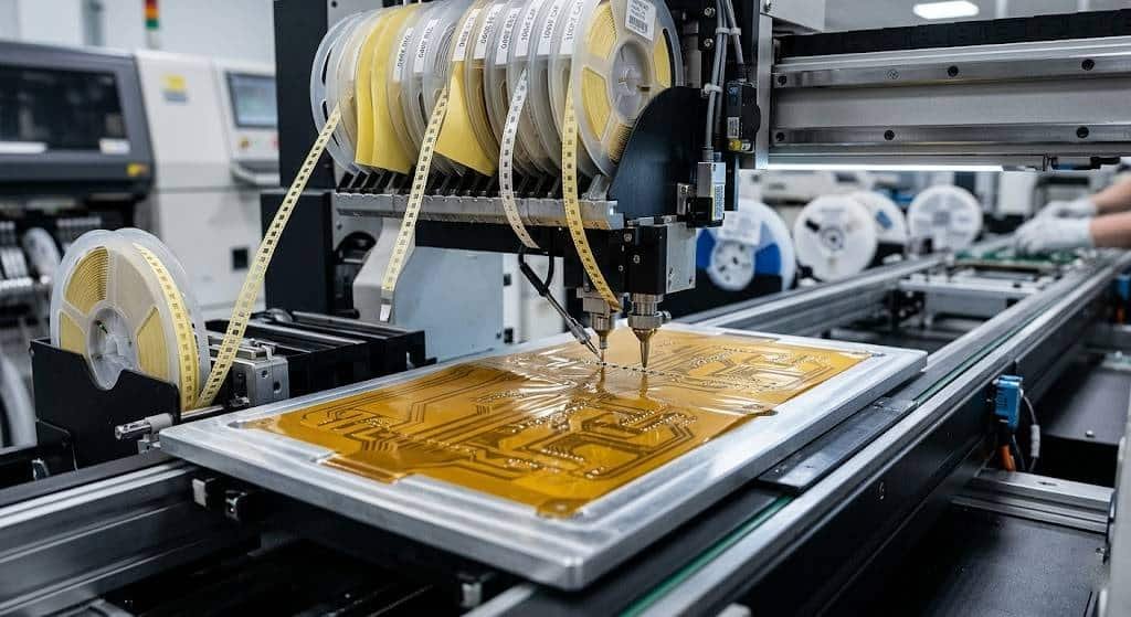
Instead of relatively inexpensive FR4 and solder mask, flexible PCBs rely on polyimide or PET films, RA or rolled copper foils, and coverlay films that have to survive repeated bending without cracking. Adhesives, bonding films, and surface finishes are also chosen with flexibility and reliability in mind, not just cost, which pushes the bare-board price higher even before any components are mounted. On the assembly side, the same fragility that makes flex useful in tight spaces also means the boards need dedicated carriers, stiffer panels, or temporary stiffeners during printing, placement, and reflow, adding extra handling steps that a rigid panel simply does not need.
From your perspective as an engineer or buyer, all of this shows up as a higher “starting point” for the project. The baseline manufacturing and assembly processes are more demanding, so even a basic flex design rarely matches the cost of a comparable rigid board built in volume. Once you accept that the cost structure is genuinely different, it becomes easier to focus on which parts of the design are truly necessary for function and reliability, and which parts are just making the build harder than it needs to be.
Small Batch vs Mass Production: How NRE and Setup Fees Dominate
The other big shock comes from quantity. When you only need 5, 10, or 50 pieces, the fixed costs of getting a flexible PCB assembly job ready to run do not shrink just because the order is small. The factory still has to review and optimize your data, generate programs, order or cut stencils, set up lines, and sometimes build custom tooling or carriers for your specific flex design.
All of these items fall under engineering time, NRE, and setup charges, and they behave like a fixed entrance ticket for each new job. On a run of a few thousand units, that ticket is barely noticeable when it is divided by the full quantity. On a small batch, the same one‑time cost is spread over only a handful of pieces, so it suddenly becomes a major part of the unit price, even if the board itself is not very complex.
This is why two quotes for the same flex design can look completely different depending on whether you ask for 10, 100, or 500 sets. The bare-board and placement cost per piece may only drop modestly with volume, but the engineering and setup portion per piece drops dramatically as you move away from very low quantities. Understanding this effect will help you decide whether it makes sense to stay strictly in prototype quantities, or to step up to a slightly larger batch to dilute those fixed costs.
When you put the “flex vs rigid” differences together with the impact of small quantities, it becomes clear why your first small‑batch flexible PCB assembly quote can feel so shocking. The good news is that once you understand where the money actually goes, you can start tuning your design, batch size, and documentation so that the next quote looks much more reasonable for the value you are getting.
What Counts as a “Small Batch” for Flexible PCB Assembly?
Typical Volume Ranges for Prototypes and Pilot Runs
If you ask ten different manufacturers what “small batch” means, you will probably get ten slightly different answers. Still, in flexible PCB assembly there are some practical ranges that most factories recognize from day‑to‑day projects. At the very low end, engineers are usually talking about 5–10 pieces for bring‑up, basic functional tests, and mechanical checks. A bit higher, 20–50 pieces often cover internal validation, early field trials, or demo units for customers. Once you reach 50–200 pieces, you are already in what many suppliers would call a pilot run rather than a pure prototype.
From a quoting perspective, all of these ranges still behave very differently from a stable mass‑production order in the thousands. Engineering, NRE, and setup work are mostly the same whether you build 10 or 1,000 units, so the factory mentally flags anything below a few hundred pieces as “small batch” for flexible PCB assembly. That does not mean small orders are unwelcome, but it does mean your quote will be dominated by fixed costs and special handling, not just by the raw component and bare‑board cost.
When you talk with a potential supplier, it helps to be explicit about where your project sits on this spectrum and what the next step might be. For example, telling them you need 20 boards now for engineering and are likely to move to 200–500 units within a few months gives them context to suggest whether it is worth investing in more robust tooling or panelization up front.
How Batch Size Changes Your Per-Unit Assembly Cost
The relationship between batch size and unit cost is not linear, and that is where many first‑time flex buyers get surprised. If the NRE, programming, and setup together add up to a fixed amount, dividing that by 10 pieces gives a very different number than dividing it by 100. The bare flex PCB and the actual placement operations may only change modestly with volume, but the “overhead per unit” shrinks quickly as you move from tiny prototype runs to slightly larger small batches.
A simple way to think about it is to imagine two layers in your quote. One layer is volume‑sensitive: bare board price breaks, component discounts, and efficiency gains in assembly as the line runs longer. The other layer is almost fixed: engineering review, stencil and tooling, programming, first‑article inspection, and any custom carriers for handling the flexible panels. At 10 pieces, that fixed layer can be a big slice of your per‑board price; at 100 pieces, the same layer is still there, but it is diluted enough that the unit cost looks much more reasonable.
This is why, in many real projects, a small step up in quantity can have an outsized impact on the per‑unit price, especially for flexible PCB assembly. If your budget allows, it is sometimes smarter to move from, say, 15 pieces to 30 or 50, just to spread those fixed costs over more units and leave yourself a few extra boards for testing or field trials. On the other hand, if you truly only need a handful, it is good to go into the quoting process with realistic expectations about how much of the price is driven by batch size alone.
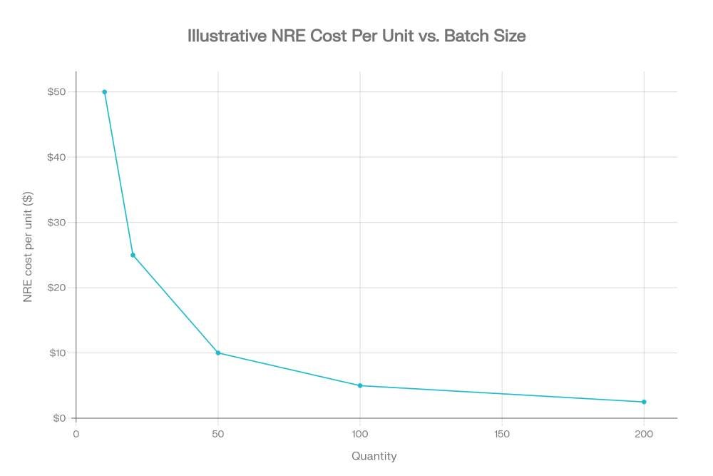
To make this more concrete, imagine a fixed engineering and setup cost of 500 USD for your flexible PCB assembly job. If you only build 10 pieces, that alone adds 50 USD per board before you count bare flex, components, or placement time. At 50 pieces, the same NRE is 10 USD per board; at 100 pieces, it drops to 5 USD per board. The technical work on the factory side is almost identical, but your unit price looks completely different simply because the fixed cost is spread over a different number of units.
Flexible PCB Assembly Cost Structure for Small Orders
Engineering, NRE, and Setup Costs for Flex Assembly
Every flexible PCB assembly job starts with a block of engineering work before a single board is built. The factory has to review your data, check DFM rules, generate programs, and design or verify panelization and carriers that make your flex circuits handle like rigid panels on the SMT line. All of this shows up in your quote as engineering time, NRE, and setup charges, very similar to what you see in a general SMT PCB assembly cost breakdown, but with extra steps specific to flex.
All of this shows up in your quote as engineering time, NRE, and setup charges, and these items barely care whether you are building 10 pieces or 1,000. For small batches, that fixed “entry ticket” can easily become one of the largest single contributors to the per‑unit price, especially if your design introduces unusual shapes, cutouts, or mixed technologies that require extra attention during programming and first‑article verification.
Bare Flex PCB Cost: Materials, Layers, and Stiffeners
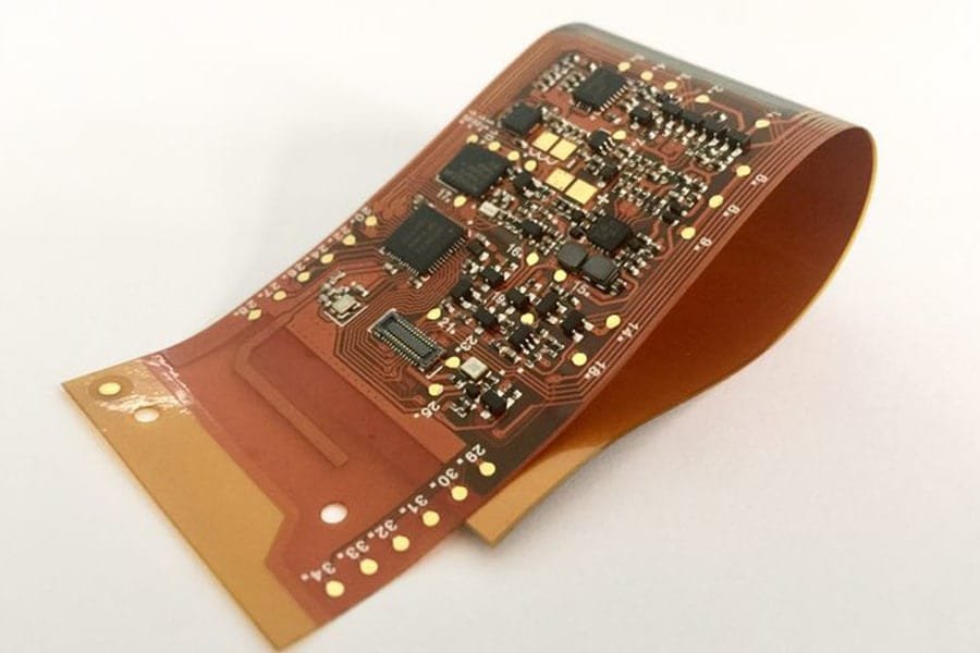
The next big slice of the cost is the bare flexible PCB itself. Compared with standard FR4, the polyimide or PET base films, RA or rolled copper foils, and coverlay films used in flex circuits are simply more expensive per square meter, which is why the flexible PCB price and cost for the bare board alone is higher even before assembly. As soon as you add more layers, tighter tolerances, or high‑performance materials, the price climbs further, especially in small batches.
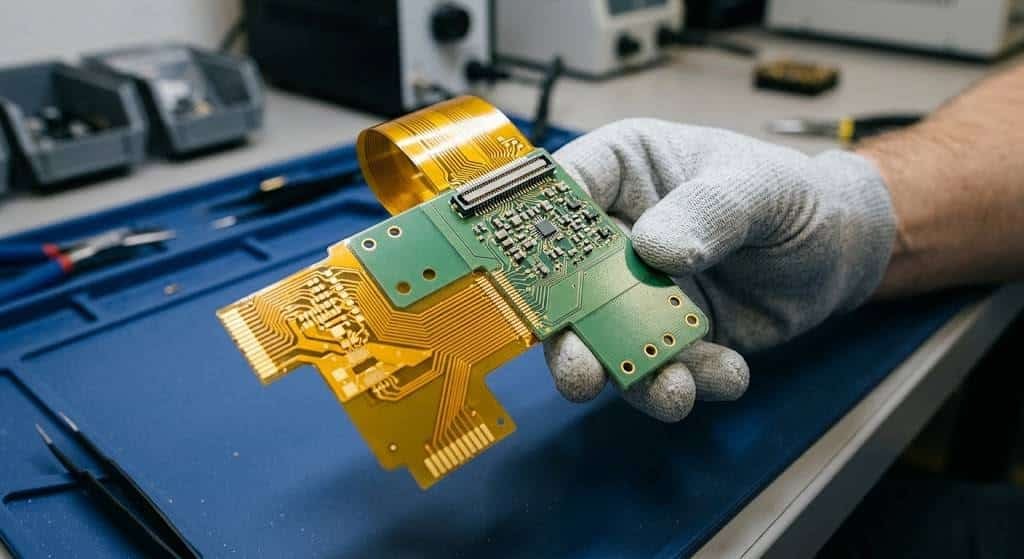
Stiffeners also play a quiet but important role in the cost structure. FR4 or polyimide stiffeners in connector areas, component zones, or bend‑limit regions add extra lamination steps, additional materials, and more process control to keep thickness and registration within spec. If you want a deeper breakdown, you can look at how PCB stiffeners impact flex PCB cost and how different stiffener materials and thicknesses change pricing in more detail.
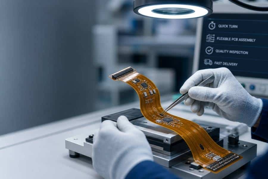
SMT Assembly on Flex: Placement Complexity and Special Handling
Once the bare flex boards arrive in the assembly area, the focus shifts to placement and soldering. The base component‑per‑placement cost might be similar to rigid boards, but the details of your design heavily influence how much time and care the line needs. High component counts, fine‑pitch ICs, BGAs, tight spacing around connectors, and double‑sided assembly all increase complexity, just as they do in dense rigid boards, but on flex they are combined with handling challenges described in many flex PCB soldering case studies.
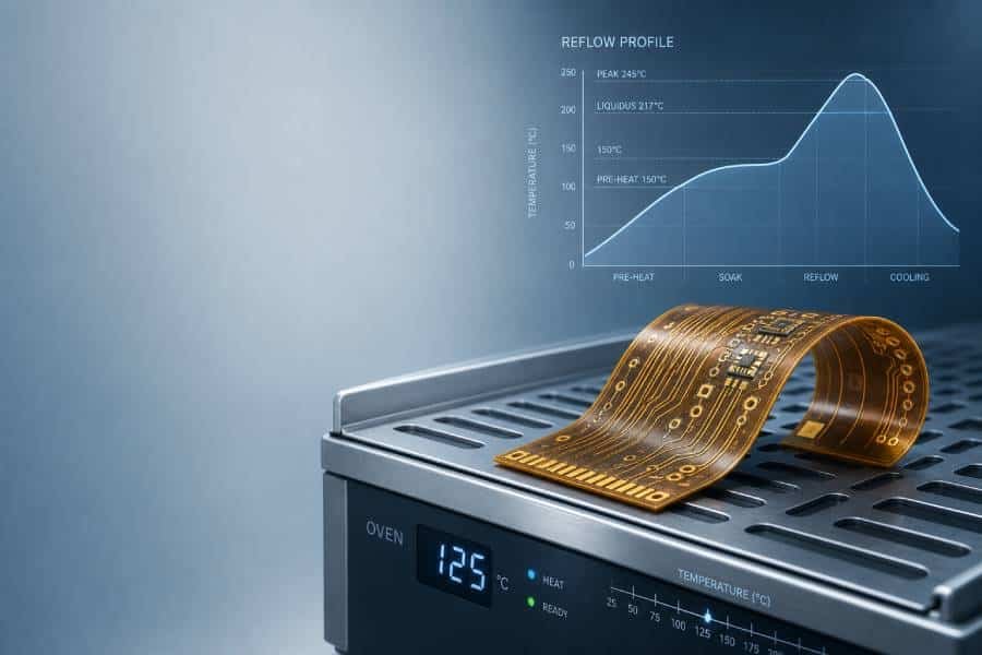
Because flex panels are not naturally rigid, the factory may need to mount them on carriers, add temporary stiffeners, or adjust print and reflow settings to keep the boards flat and prevent warping or excessive movement during soldering. These precautions are essential for yield and reliability, but they also translate into extra process steps and more operator time compared with a straightforward rigid FR4 assembly. In small batches, the cost of building and validating these handling strategies has very little volume to hide behind.
Component Cost and Sourcing Model (Turnkey vs Consignment)
Components themselves can be a surprisingly large part of the bill on a small flex project. If you ask the assembly house to supply parts on a turnkey basis, they have to source everything in low quantities and account for attrition, similar to what is described in a general SMT components guide and turnkey vs consignment SMT assembly discussions. On a small batch, the combination of niche flex connectors and low purchasing lots can make the component portion of your small-batch flexible PCB assembly cost look heavier than you expect.
In a consignment model, you control the parts buying, but the factory still has to handle incoming inspection, storage, and kitting, and they may need extra overage if the design is challenging. Either way, the combination of small purchasing lots and the typical mix of specialized components used on flexible PCBs means the component portion of your quote often looks “heavier” than on a mature, high‑volume rigid board.
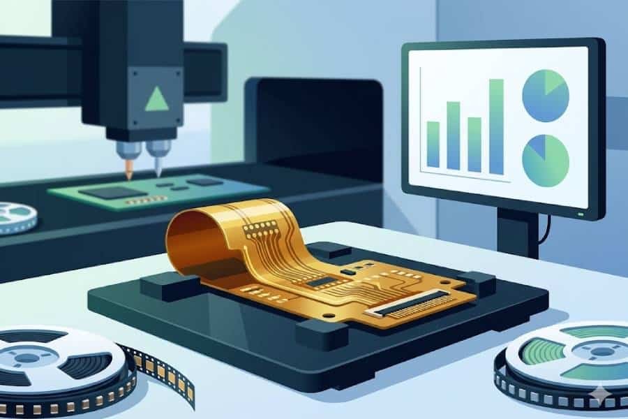
Inspection and Test: AOI, X-Ray, and Functional Testing
Quality control steps like AOI in SMT PCB assembly, X-ray inspection for PCB assembly, and ICT/FCT are often essential when you have fine‑pitch parts or BGAs on flex. On a small batch, their cost has very few units to spread across, which is why these line items can feel large but are still critical to protect your prototypes and early pilot builds.
Packaging, Shipping, and Yield Risk in Small Batches
Finally, there are the costs that show up at the end of the line: packaging, shipping, and yield. Flexible circuits need careful packing to avoid kinks, overstress, and ESD issues during transport, which means the factory may use custom trays, anti‑static bags, separators, or reels rather than simple bulk packaging. For a low‑volume job, the cost of setting up and validating this packaging process is once again divided by only a small number of pieces.
Yield also has a different psychological weight in small batches. Losing a few boards to unavoidable defects or learning‑curve issues is expected in any production environment, but if the total order is only 10 or 20 units, every scrapped board hurts both your budget and your schedule. To protect yield, the supplier might choose more conservative process windows, extra inspections, or backup panels, all of which add some cost but significantly reduce the risk that you end up short of working assemblies when you need them most.
Example Price Scenarios for Small-Batch FPCBA
Scenario 1: 10 Pieces of a Simple Single-Sided Flex PCB
Imagine you have a small single‑sided flex board with basic digital and power circuitry, mostly 0603 passives, a few mid‑pitch ICs, and one flex connector. You only need 10 pieces for bring‑up and fitting tests in a mechanical assembly. On paper, this sounds like a “cheap” job—until you see the quote.
In this kind of build, the bare flex PCB and the component cost are noticeable but not the main story. What really drives the price is the fixed engineering and setup work: DFM, panelization, stencil and program preparation, and the time to tune printing and reflow for your specific flex stackup. When those fixed costs are divided across just 10 units, they add a surprisingly large amount to each board, even though the design itself is technically straightforward. This is the classic situation where the per‑unit price looks high, but the total project cost is still moderate simply because the quantity is so small.
For projects like this, it often makes sense to ask yourself whether 10 pieces is truly enough. If your budget can handle 20 or 30, you spread the same NRE over more boards and give your team spare units for destructive tests, solder‑rework practice, or field demos, without paying another round of setup fees later.
Scenario 2: 50 Pieces of a Dense Double-Sided Flex with BGA and Stiffeners
Now consider a more demanding design: a double‑sided flex with a BGA processor, fine‑pitch connectors, and multiple stiffeners under dense SMT areas. You need 50 pieces for internal validation and early customer testing. Here, both the bare board and the assembly steps are significantly more complex than in Scenario 1.
The flex stackup may use higher‑end materials to keep impedance and bending performance under control, and the stiffeners require precise lamination in several regions, which raises the bare‑board cost. On the assembly side, the BGA and fine‑pitch parts drive tighter process windows, more careful paste printing, and almost certainly X‑ray inspection for hidden joints. The factory will also spend extra time verifying the first articles, dialing in reflow profiles, and confirming that the flex‑plus‑stiffener structure behaves as expected through the entire SMT process.
Because the quantity is 50 instead of 10, the NRE and setup cost per unit are much more reasonable, but the complexity of the design keeps the overall unit price in a higher bracket. This kind of build is where an experienced flexible PCB assembly partner really matters: someone who has already debugged similar BGA‑on‑flex and stiffener combinations can hit good yields quickly instead of learning on your project. In practice, that experience translates not only into reliability, but also into fewer scrap boards and fewer “mystery” costs for rework.
Scenario 3: 100 Pieces of a Dynamic-Flex Design with Advanced Materials
For the third scenario, picture a flex that will be bent repeatedly in the final product—perhaps in a wearable device, a hinge, or a robotics application. The design uses RA copper, carefully tuned trace routing in the bend areas, and possibly multiple flex regions connected to rigid sections. You order 100 pieces as a pilot build before committing to full mass production.
Here, the bare‑board cost reflects both advanced materials and strict process control on copper grain and coverlay alignment. The assembly flow may not be much more complex than Scenario 2 in terms of components, but the supplier has to be cautious with handling, fixturing, and post‑reflow inspection to ensure there are no micro‑cracks or stress concentrations that could fail under dynamic bending. If any functional or mechanical cycling tests are required, those add another layer of time and equipment.
The upside is that, at 100 units, the fixed engineering and setup portion of the cost per board is now relatively small compared with the material and process‑driven costs. You are essentially paying for the combination of high‑end flex technology and careful assembly needed to survive real‑world bending, not for the privilege of running a tiny job. For many teams, this is a sweet spot: large enough to justify serious process optimization and testing, but still small enough to catch design issues before a full production launch.
Design Choices That Drive Small-Batch Flex Assembly Cost
Material and Stackup: PI vs PET, RA vs ED Copper, and Layer Count
Choosing polyimide vs PET, RA vs ED copper, and adding layers are all covered in detail in a flexible PCB materials guide and dedicated articles on PI vs PET in flexible PCBs and RA copper vs ED copper. For a small batch, each of these stackup decisions shows up directly in your bare-board cost and therefore in your small-batch flexible PCB assembly cost.
Trace Width, Spacing, and Fine-Pitch Components on Flex
Layout details also play a big role. Very fine trace widths and spacings push the flex fabrication process into tighter etching and registration tolerances, which increases scrap risk and process cost. At the same time, fine‑pitch BGAs, QFNs, and dense connector footprints demand more precise solder paste printing, more careful placement, and more time‑consuming inspection and rework during assembly.
On a dense design, a small change—like relaxing pitch where possible, opening up spacing around critical pads, or simplifying via‑in‑pad usage—can make the board much easier to build without changing the core functionality. For small batches, those “DFM kindnesses” often translate directly into fewer assembly surprises, higher first‑pass yield, and less time spent chasing marginal solder joints under the microscope.
Stiffener Design: When You Need It and How It Affects Pricing
Stiffeners are one of the most powerful tools in flexible PCB design, but they are not free. Every FR4 or polyimide stiffener region adds material, lamination steps, and registration requirements to the flex fabrication process. When stiffeners sit under SMT components or connectors, they also influence panelization and assembly handling, which can change how the boards are supported during printing and reflow.
The key question is not “Can we add a stiffener?” but “Exactly where and how thick does it need to be?” Well‑placed, right‑sized stiffeners can actually reduce assembly cost by making printing and placement more stable, while unnecessary or oversized stiffener areas just make the build more complex without adding real reliability. Working through a few alternatives with your flex assembly partner early—such as FR4 vs polyimide, different thicknesses, or combining stiffeners with local copper thieving—often reveals a solution that hits both cost and mechanical targets.
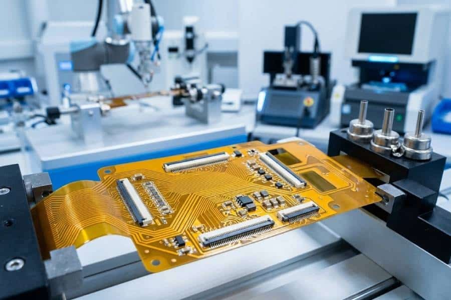
Panelization and Array Design for Flexible PCB Assembly
Finally, how your flex boards are panelized may be one of the biggest invisible cost levers. Flexible circuits rarely run as loose single pieces through SMT lines; they are mounted on carriers, nested in arrays, or combined with break‑off rails to behave like rigid panels during assembly. A thoughtful panel design can maximize the number of usable boards per panel, simplify stencil design, and make depanelization cleaner and faster.
For small batches, you may only build a handful of panels, but the choice of array layout still affects how many times printers, placement heads, and reflow ovens have to cycle to finish your order. A panel that carries a few more boards per run, avoids awkward part orientations, and leaves enough room for fiducials and tooling holes can shave off both time and scrap risk. This is one area where your supplier’s experience with previous high‑volume flex projects is especially valuable: they already know what panel formats run smoothly on their lines, so you do not have to learn it the hard way on your prototype budget.
Practical Ways to Reduce Flexible PCB Assembly Cost for Low Volumes
Prepare Complete Engineering Data to Avoid Re-Spins
One of the simplest ways to waste money on small-batch flex builds is to send incomplete or inconsistent data. Missing notes about bend areas, unclear stackup information, outdated BOMs, or pick‑and‑place files that do not match the latest Gerber revision all translate into extra engineering time, questions back and forth, or, in the worst case, scrapped boards and a full re‑run. When you are only building a handful of units, even a single avoidable respin hurts.
Before requesting a quote, make sure your core files are in sync: Gerber or ODB++ data, a clear flex stackup, BOM with approved alternates, pick‑and‑place coordinates, assembly drawings, and any critical notes about stiffeners, bending regions, or special handling. A few extra minutes spent on a clean data package can easily save days of delay and a second round of NRE and setup charges.
Simplify the Design Where Possible Without Sacrificing Reliability
It is tempting to push every flex design to the limit—tight spacing, aggressive layer counts, and multiple stiffener regions “just in case”. The problem is that each of these choices increases fabrication difficulty, reduces process margins, and raises the chances of yield loss or rework, which show up very clearly in small-batch pricing. In many cases, you can meet your electrical and mechanical requirements with a slightly more forgiving layout.
Examples include relaxing minimum trace and space where high density is not strictly needed, avoiding unnecessary impedance‑critical routes, consolidating stiffeners into fewer, well‑defined regions, and keeping component densities reasonable in bend‑adjacent zones. These adjustments may not change the function of your product at all, but they make life much easier for the fabrication and assembly lines, which in turn keeps both NRE and per‑unit costs under control.
Optimize Your BOM and Sourcing Strategy
On low‑volume flex projects, BOM choices often swing the total cost more than designers expect. Niche connector series, exotic passives, or “nice to have” components with tight supply can force the factory to buy full reels or meet high minimum order quantities, even if you only need a few dozen parts. That extra material sits behind your quote, wrapped into the component cost portion.
Where possible, align part choices with widely available, standard footprints that your assembly partner already sees in volume work. Ask whether a more common connector, resistor array, or capacitor series would work electrically and mechanically. If you prefer to buy parts yourself, coordinate closely on required overage and packaging format so you do not pay twice—once in your purchasing and once in handling headaches at the factory.
Work with Your Assembly Partner on Panelization and Test Strategy
Finally, treat panelization and test as joint design problems, not afterthoughts. A panel format that matches your supplier’s standard carriers and stencil sizes can reduce setup time, improve print quality, and make depanelization smoother, all of which are especially valuable when you only have a limited number of flex boards to begin with. Involving the factory early in panel design can reveal small tweaks—rotating parts, adjusting break‑off tabs, or redistributing fiducials—that improve throughput and reduce scrap.
The same logic applies to test. Instead of asking for a fully custom fixture from day one, you might start with a simpler functional test setup or a combination of AOI and targeted probing that fits your budget and schedule for the first small batch. As volumes grow, you can invest in more sophisticated ICT or FCT fixtures once the design is stable. In other words, you do not have to choose between “no test” and “full mass‑production test”; there is usually a middle ground that keeps risk under control without overwhelming a low‑volume flex project.
When to Move from Small Batch to Larger Volume
How NRE and Setup Costs Get Diluted as Volume Increases
If you look back at the cost structure we discussed earlier, one pattern stands out: engineering, NRE, and setup costs barely change with quantity, while bare-board, components, and placement scale more smoothly. In very small batches, that fixed “entry ticket” is a big part of your per‑unit price; as you step up to 50, 100, or a few hundred pieces, the ticket is still there—but each board only carries a small fraction of it.
Practically, this means there is often a “knee” in the cost curve. Below a certain quantity, adding more units causes the per‑unit price to drop quickly because you are mainly diluting fixed costs. Beyond that point, additional volume brings smaller, more incremental savings. If you already know you will need more boards in the near future—say, for extended field trials or pre‑production builds—it can be cheaper overall to plan a slightly larger batch now rather than pay the full setup cost again for a second small order.
Balancing Local Quick-Turn vs Offshore Production for Flex Assembly
Another timing decision is where to build each stage of your project. For the very first prototypes, local or quick‑turn assembly can be worth the premium: you get faster feedback, easier communication across time zones, and the ability to iterate layout and BOM rapidly. At this point, the absolute number of boards is small enough that speed matters more than shaving a few dollars off each unit.
Once the design is stable and you are looking at 50, 100, or more flexible PCB assemblies, offshore or higher‑volume‑optimized factories often become more attractive. Their material purchasing, process tuning, and panelization strategies are built around larger runs, so they can offer a better balance of cost and reliability at those quantities. Many teams end up with a hybrid strategy: build the first 10–20 flex boards locally for bring‑up, then move the 50–200 piece pilot run to a partner that has deep experience with mass‑production flex while still being comfortable with low-volume orders.
How to Get an Accurate Flexible PCB Assembly Quote for Small Batches
Files and Information Your Supplier Needs to Quote Correctly
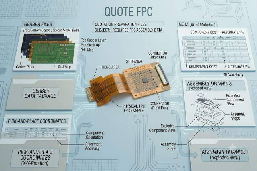
The fastest way to get a clean, realistic quote for small‑batch flexible PCB assembly is to give your supplier everything they need up front. In practice, that means a complete technical package, not just Gerber files dropped into an email. At a minimum, you should be ready to provide:
- Fabrication data: Gerber or ODB++ files, including drill files, flex stackup, and clear notes on materials, thicknesses, coverlay, and stiffeners.
- Assembly data: BOM with manufacturer part numbers and approved alternates, pick‑and‑place (centroid) file, reference designators, assembly drawings, and any special requirements like no‑clean flux or conformal coating.
- Handling and reliability expectations: which areas will bend (and how often), where stiffeners are needed, any keep‑out zones, and whether the boards will see harsh temperature or vibration in use.
Supplying this information in one organized package lets the factory estimate not only the bare‑board price and placement effort, but also the NRE, tooling, carriers, and inspection steps they will need for your specific flex design. The more guesswork they have to do, the more conservative—and therefore higher—the quote tends to be.
Common Details That Can Change the Final Price
Even when the basic files are present, a few “small” details can still move the final price much more than expected. Examples include:
- Stiffener specifications: material, thickness, and exact regions; vague notes like “add FR4 stiffener under connector” force the supplier to assume worst‑case complexity.
- Surface finish and copper type: ENIG vs hard gold, RA vs ED copper, and any requirement for controlled impedance or tight thickness tolerance.
- Test strategy: whether you need basic power‑on checks only, AOI plus X‑ray for BGAs, or a defined ICT/FCT procedure with fixtures.
- Packaging and shipping preferences: flat packs vs reels, special ESD precautions, labeling requirements, or multi‑destination shipments.
If you know these requirements before quoting, include them. If you are flexible, say so explicitly—many suppliers can suggest alternative finishes, stiffener options, or test approaches that meet your real needs at a lower cost for small batches.
Next Step: Prepare Your Files for a Flexible PCB Assembly Quote
By the time you reach this point in the guide, you have a clear picture of where the money goes in small‑batch flexible PCB assembly and which design choices drive cost up or down. The natural next step is to turn that understanding into a better first quote: gather your latest Gerber/ODB++ data, BOM, pick‑and‑place file, and assembly drawings, and review them once with a “supplier’s eye” to check that they are consistent, complete, and honest about materials, stiffeners, and test expectations.
When you send this package to a flexible PCB assembly service provider, you can also highlight what you are optimizing for—lowest small-batch cost, fastest turnaround, or a smooth path from 10 pieces to 100 and beyond—and simply request a flexible PCB assembly quote with those priorities clearly stated.
Flexible PCB Assembly Cost FAQ for Small Batches
There is no single industry‑wide MOQ, but many suppliers treat anything from 5–10 pieces as a very small prototype run and 20–50 pieces as a typical “small batch” for flexible PCB assembly. Below a few dozen boards, fixed engineering and setup costs dominate the unit price, so the MOQ is often more about economics than about what the line can physically build.
The per‑board cost can vary from tens to hundreds of dollars depending on materials, layer count, stiffeners, component mix, and test requirements, even at the same quantity. For very small batches like 5–10 pieces, the NRE and setup portion per unit can be larger than the actual fabrication and placement cost, which is why quotes often look “expensive” compared with mature rigid FR4 products.
Most of the shock comes from fixed engineering, programming, stencil, and setup work being spread over only a handful of boards. On top of that, flex materials, stiffeners, and special handling add a higher baseline cost than a simple rigid FR4 job, so even a “small” design does not scale down linearly in price with quantity.
Supplying your own components can help if you already have stock or can buy parts more efficiently, but it does not remove handling, kitting, and attrition on the assembly line. For small batches, the best approach is usually to discuss BOM and sourcing options with your assembly partner and decide case by case whether turnkey, consignment, or a hybrid model gives the best overall cost and risk balance.
Often yes: once the engineering data, panelization, programs, and tooling are in place and proven, future builds of the same flex design may have much lower or even negligible additional NRE. If you know you will need several small batches over time, it is worth telling your supplier so they can structure the initial setup with reuse in mind instead of treating each order as a one‑off job.
Lead time depends on both flex fabrication and assembly capacity, but for many projects a realistic window is 2–4 weeks from complete data handoff to shipment, assuming standard materials and no major design issues. Truly urgent quick‑turns are often possible at a premium, especially for simpler flex designs, while complex multilayer or dynamic‑flex builds may need additional time for material procurement, panel trials, and reliability checks.