


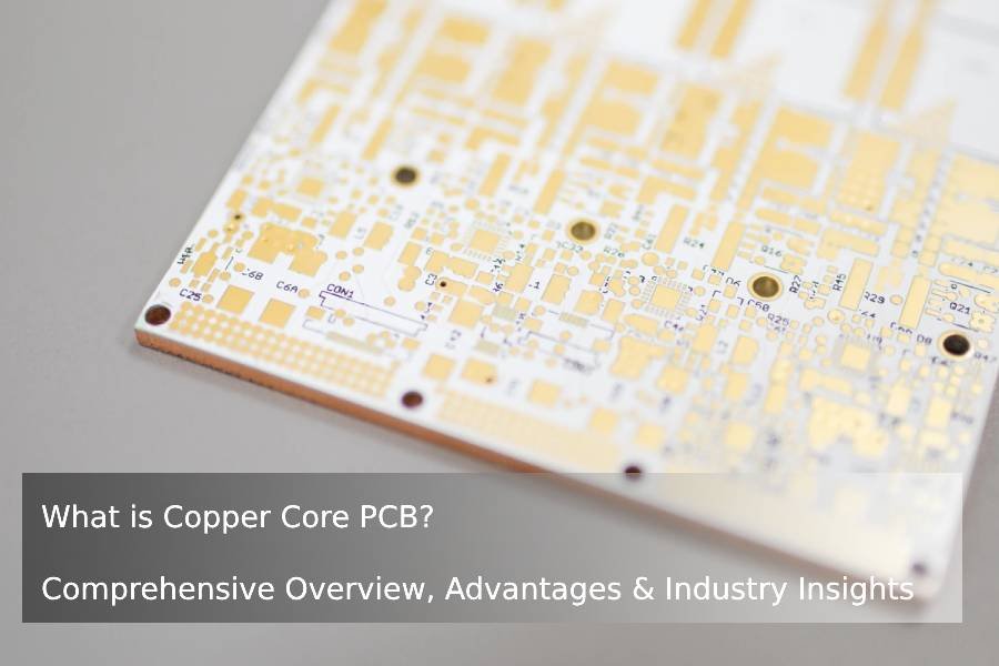
Metal Core PCB (MCPCB) Manufacturing Service in China
JHYPCB is a dedicated metal core PCB manufacturer in China, offering fast MCPCB prototypes and small-batch production with aluminum and copper cores at competitive prices for LED and power electronics.
- Fast metal core PCB (MCPCB) prototyping with flexible low-volume orders
- Aluminum & copper metal core PCBs optimized for LED and power electronics
- Competitive pricing with engineering support for thermal design and DFM review
Why Metal Core PCBs (MCPCBs) for Your High-Power Designs?
High-power electronic designs face critical thermal management challenges that traditional FR4 PCBs cannot adequately address. Metal core PCBs (MCPCBs) with aluminum or copper substrates provide superior heat dissipation, ensuring your LED arrays, power converters and automotive electronics operate reliably under demanding conditions.
Don’t let thermal issues limit your high-power designs. Metal core PCBs from JHYPCB provide the thermal performance, reliability and cost-effectiveness you need.
WHAT WE DO
Metal Core PCB
& MCPCB Prototype Service
JHYPCB focuses on fast and affordable metal core PCB (MCPCB) prototypes for LED, automotive and power electronics projects. Our team helps you quickly validate thermal performance and manufacturability, then scale from small-batch runs to reliable mass production without changing suppliers.
Fast MCPCB Prototyping
Get metal core PCB prototypes in as little as X–Y days, with flexible low MOQ so you can validate designs quickly without heavy upfront costs.
Aluminum & Copper Metal Core Options
Choose from aluminum and copper MCPCBs with different thermal conductivity ratings to match your LED, automotive or power electronics thermal requirements.
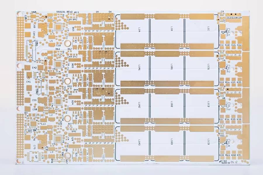
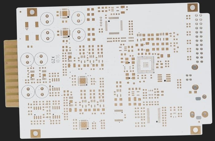
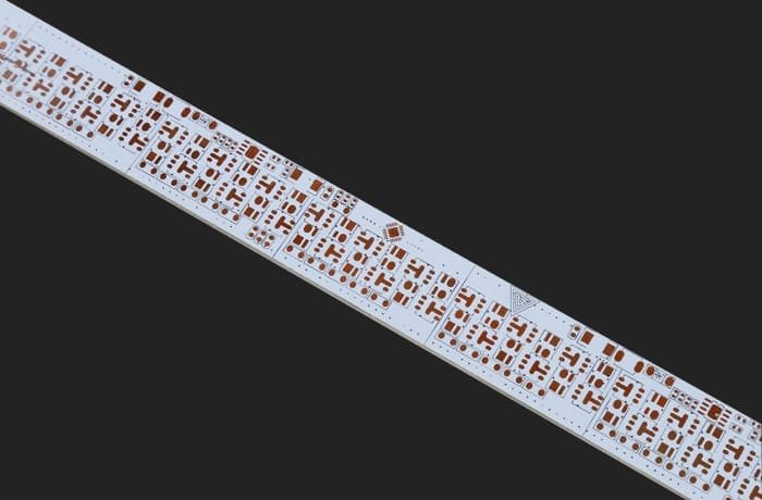
Metal Core PCB Capabilities
JHYPCB offers comprehensive metal core PCB (MCPCB) manufacturing capabilities to support your LED, automotive and power electronics projects. From single-sided aluminum MCPCBs to multilayer copper core PCBs, we deliver reliable thermal management solutions with flexible specifications and competitive lead times.
| Parameter | Specifications |
|---|---|
| Metal Base Materials | Aluminum (5052, 6061), Copper |
| Thermal Conductivity | 1.0–3.0 W/m·K (aluminum dielectric) Up to 8.0 W/m·K (copper core available) |
| Layer Count | Single-sided, double-sided, multilayer metal core PCB |
| Metal Base Thickness | 0.8 mm, 1.0 mm, 1.5 mm, 2.0 mm, 3.0 mm (custom available) |
| Copper Thickness | 1 oz, 2 oz, 3 oz, 4 oz (up to 6 oz available) |
| Dielectric Thickness | 75–200 μm (standard), custom upon request |
| Board Size Range | Min: 10 × 10 mm / Max: 500 × 610 mm |
| Minimum Trace/Space | 4/4 mil (0.1/0.1 mm) standard, 3/3 mil available |
| Surface Finish | HASL, Lead-free HASL, ENIG, OSP, Immersion Silver, Immersion Tin |
| Solder Mask Color | White (standard for LED MCPCB), Black, Green, Blue, etc. |
| Prototype Lead Time | 3–5 days (expedited available) |
| Mass Production Lead Time | 7–12 days depending on complexity and volume |
| MOQ (Minimum Order Quantity) | 1 pcs for prototype, flexible for small batches |
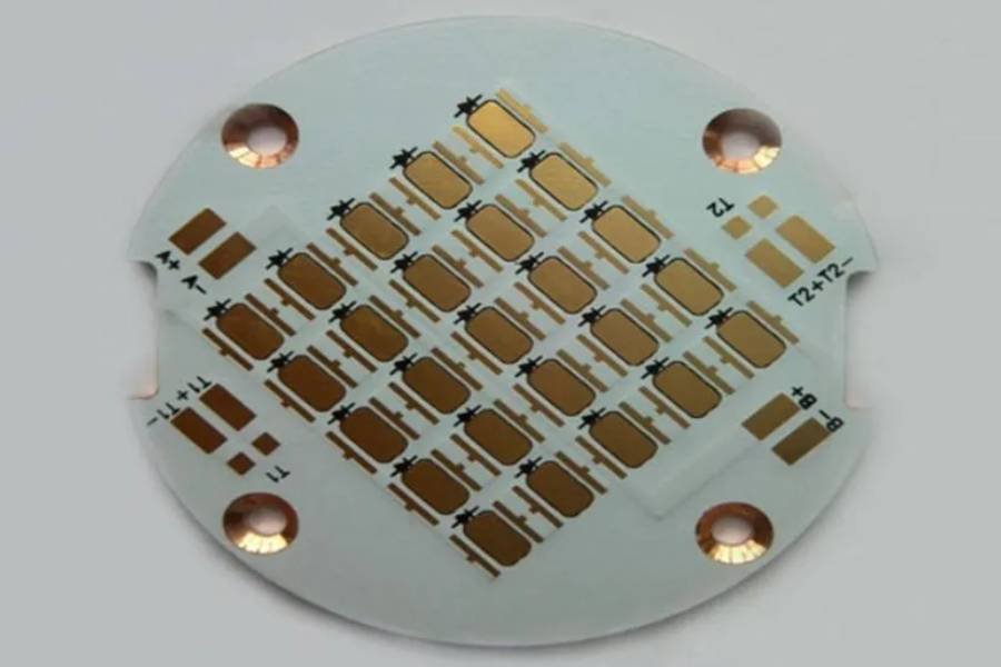
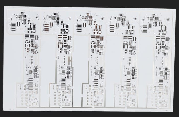
Applications of Metal Core PCBs
Metal core PCBs (MCPCBs) are widely used in high-power and heat-sensitive applications where excellent thermal management is critical. JHYPCB provides aluminum and copper MCPCBs tailored for LED lighting, automotive electronics, power conversion and other demanding industries, helping you achieve better performance, reliability and longer product lifespan.
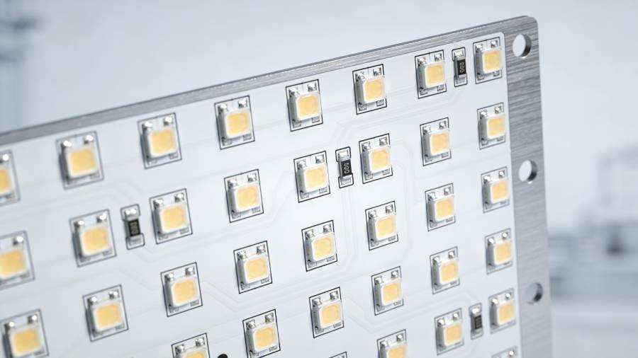
LED Lighting & Illumination
Automotive Electronics
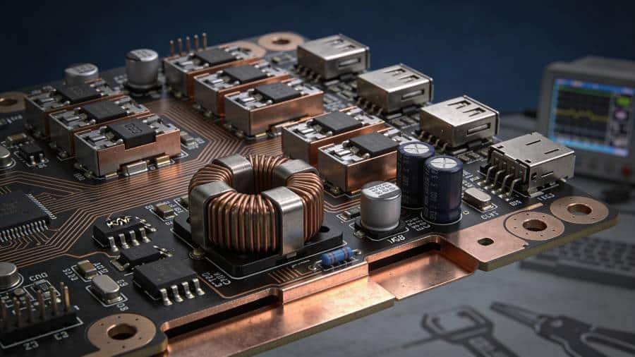
Power Electronics & Conversion

Telecom & Industrial Control
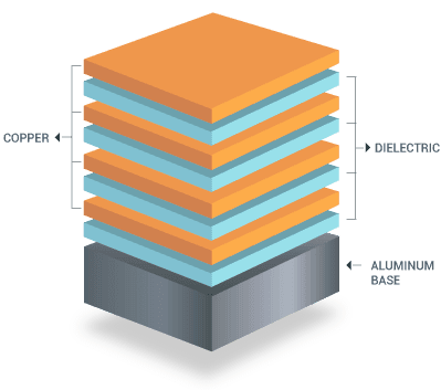
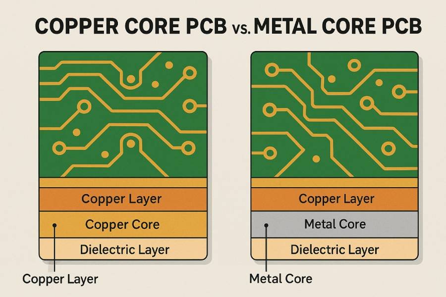
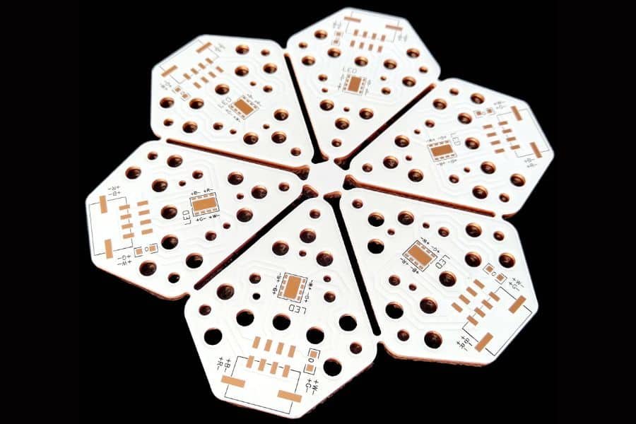
Metal Core PCB Materials & Stack-Up Options
Choosing the right metal core PCB material and stack-up is critical for optimizing thermal performance and cost. JHYPCB offers a range of aluminum and copper metal core PCBs with various dielectric options to match your LED, automotive or power electronics thermal requirements.
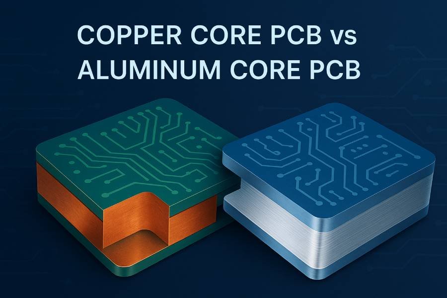
Aluminum vs Copper Metal Core PCBs
Aluminum metal core PCBs are the most popular choice for LED lighting and general high-power applications due to their excellent balance of thermal performance and cost-effectiveness. Aluminum substrates (typically 5052 or 6061 alloys) offer good thermal conductivity (120–200 W/m·K for the metal base), lightweight design and easy machinability. Combined with thermally conductive dielectric layers (1.0–3.0 W/m·K), aluminum MCPCBs effectively dissipate heat while keeping costs competitive for both prototypes and mass production.
Copper metal core PCBs provide superior thermal conductivity (up to 400 W/m·K for the metal base) and are ideal for ultra-high-power applications such as RF amplifiers, high-power motor drivers and extreme thermal management designs. While copper MCPCBs cost more than aluminum, they deliver unmatched heat spreading performance when every degree matters. JHYPCB can help you evaluate whether copper is necessary for your specific thermal budget.Lorem ipsum dolor sit amet, consectetur adipiscing elit. Ut elit tellus, luctus nec ullamcorper mattis, pulvinar dapibus leo.
Thermally Conductive Dielectric Layers
The dielectric layer electrically insulates the circuit from the metal base while enabling heat transfer. JHYPCB offers a range of dielectric materials with different thermal conductivity levels to match your performance and cost requirements.
| Dielectric Type | Thermal Conductivity | Typical Applications |
|---|---|---|
| Standard Dielectric | 1.0–1.5 W/m·K | General LED lighting, low-to-medium power |
| High Thermal Dielectric | 2.0–3.0 W/m·K | High-power LED arrays, automotive lighting |
| Ultra-High Thermal Dielectric | 3.0–8.0 W/m·K | Extreme power density, RF amplifiers, copper base |
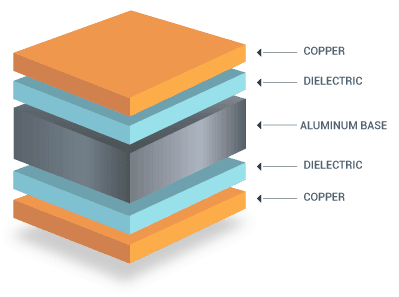
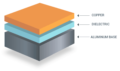
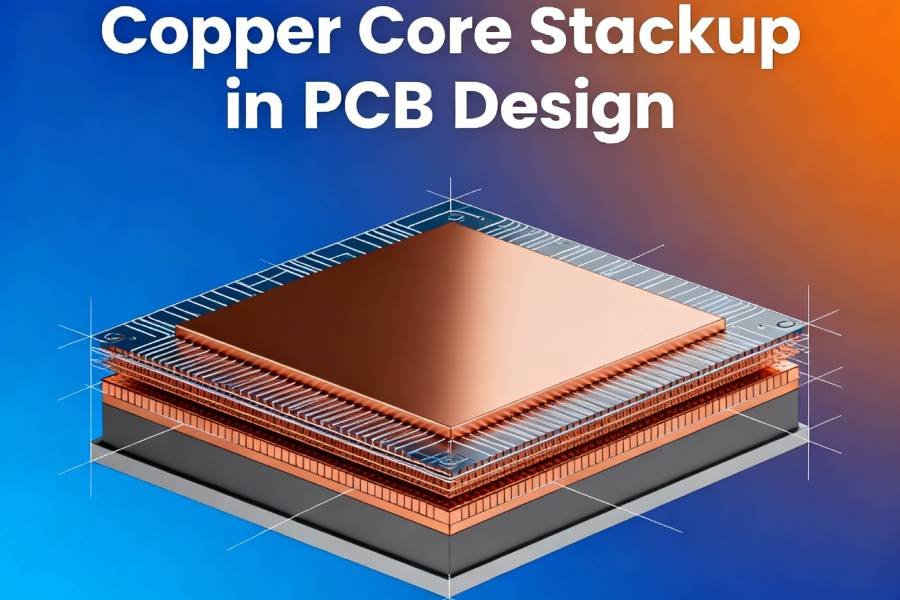
Typical MCPCB Stack-Up Structure
A typical metal core PCB stack-up consists of three layers: a copper circuit layer for electrical connectivity, a thermally conductive dielectric layer for insulation and heat transfer, and a metal base (aluminum or copper) for mechanical support and heat dissipation. JHYPCB’s engineering team can recommend the optimal stack-up configuration based on your power density, board thickness and thermal performance targets.
Not sure which metal core PCB material is right for your design?
Metal Core PCB Manufacturing Process & Quality Control
JHYPCB follows strict metal core PCB manufacturing procedures and quality control standards to ensure every MCPCB meets your thermal, electrical and mechanical requirements. Our advanced equipment and experienced team handle the unique challenges of metal-backed PCB production—from precision drilling through metal substrates to managing thermal expansion and preventing board warpage.
Material Preparation & Cutting
We start with high-quality aluminum or copper metal core substrates (5052/6061 aluminum alloys or C1100 copper) pre-laminated with thermally conductive dielectric layers. Metal cores are precision-cut to the required board dimensions using CNC routing or shearing, ensuring tight dimensional tolerances for subsequent processing steps.
Drilling & Via Formation
Precision CNC drilling creates holes for component mounting and electrical vias through the copper circuit layer and dielectric (stopping at the metal base for single-sided MCPCBs, or through all layers for double-sided designs). Metal core PCB drilling requires specialized drill bits and parameters due to the hardness of aluminum/copper substrates, and we carefully control drill speed and feed rate to prevent delamination and ensure clean hole walls.
Circuit Imaging & Etching
A photoresist layer is applied to the copper circuit layer, then exposed and developed using your circuit pattern (from Gerber files). The copper is chemically etched to form traces, pads and other circuit features. For high-power metal core PCBs, we support thick copper (2–6 oz) with controlled etching to maintain precise trace widths and minimize undercutting, ensuring reliable current-carrying capacity.
Plating (Double-Sided / Multilayer MCPCBs)
For double-sided or multilayer metal core PCBs, electroless copper deposition and electroplating are used to metallize through-holes and build up copper thickness in vias for reliable electrical connectivity between layers. Our plating process is optimized for metal-backed boards to ensure uniform copper distribution and strong adhesion to the dielectric layer.
Solder Mask & Silkscreen Application
A solder mask layer (typically white for LED metal core PCBs to maximize light reflection, or other colors as specified) is applied and UV-cured to protect copper traces and define solderable areas. Silkscreen legend is then printed to mark component designators, polarity and company logos. We use high-contrast inks for clear legibility during assembly and inspection.
Surface Finish
Exposed copper pads are protected with your chosen surface finish: HASL (Hot Air Solder Leveling), lead-free HASL, ENIG (Electroless Nickel Immersion Gold), OSP (Organic Solderability Preservative), immersion silver or immersion tin. Each finish offers different shelf life, solderability and cost trade-offs. ENIG is popular for metal core PCBs in automotive and high-reliability applications due to its excellent solderability and long-term stability.
Routing, V-Scoring & Final Inspection
Individual metal core PCB boards are separated from production panels using CNC routing or V-scoring. The metal substrate requires specialized tooling to achieve clean edges without burrs or delamination. Every board undergoes rigorous final inspection including visual checks, dimensional verification, electrical testing (continuity, isolation) and thermal performance spot-checks to ensure compliance with your specifications before packaging and shipment.
Specialized Quality Control for Metal Core PCBs
- Thick Copper Management:
We carefully control plating and etching parameters when working with thick copper (2–6 oz) to ensure uniform thickness distribution and prevent stress-related defects during thermal cycling. - Thermal Expansion & Warpage Control:
Metal core PCBs experience different thermal expansion rates between the metal base and dielectric/copper layers. We use stress-relieving lamination processes and post-cure heat treatment to minimize internal stress and prevent board warpage, especially critical for large-format MCPCBs. - Dielectric Adhesion Testing:
We perform peel strength tests on sample boards to verify strong adhesion between the dielectric layer and metal base, ensuring the MCPCB maintains structural integrity under thermal and mechanical stress. - Thermal Conductivity Verification:
For high-performance applications, we can provide thermal conductivity testing reports to verify that the dielectric layer meets your specified W/m·K requirements. - Lorem ipsum dolor sit amet, consectetur adipiscing elit. Ut elit tellus, luctus nec ullamcorper mattis, pulvinar dapibus leo.
Certifications & Compliance
JHYPCB is committed to delivering metal core PCBs that meet international quality and safety standards. Our manufacturing facility is certified to ensure consistent quality and compliance for automotive, industrial and commercial applications.
- ISO 9001:2015 Quality Management System Certified
- RoHS & REACH Compliant for Lead-Free, Environmentally Friendly Production
- 100% Electrical Testing & AOI (Automated Optical Inspection)
- IPC-A-600 Workmanship Standards for PCB Acceptability
Interested in learning more about our metal core PCB manufacturing capabilities?
Metal Core PCB vs FR4 PCB: Which Is Right for Your Design?
While traditional FR4 PCBs are suitable for many applications, metal core PCBs (MCPCBs) offer superior thermal management for high-power and heat-sensitive designs. Understanding the key differences between metal core PCB and FR4 helps you choose the right substrate for LED lighting, automotive electronics, power supplies and other demanding applications.
Key Differences Between Metal Core PCB and FR4 PCB
| Feature | Metal Core PCB (MCPCB) | FR4 PCB |
|---|---|---|
| Base Material | Aluminum or copper metal substrate | Fiberglass-reinforced epoxy resin |
| Thermal Conductivity | 1.0–8.0 W/m·K (depending on dielectric layer and metal base) | 0.3–0.4 W/m·K (standard FR4) |
| Heat Dissipation | Excellent – metal base acts as integrated heat sink, rapidly transferring heat away from components | Limited – requires additional heat sinks or thermal vias for high-power applications |
| Typical Applications | High-power LED lighting, automotive headlights, power converters, motor drivers, RF amplifiers | General-purpose electronics, consumer devices, low-to-medium power applications |
| Mechanical Strength | Higher rigidity and durability due to metal base | Good, but less rigid than metal substrates |
| Weight | Heavier (aluminum lighter than copper) | Lightweight |
| Cost | Moderately higher material cost, but can reduce overall system cost by eliminating external heat sinks | Lower material cost |
| Design Complexity | Single-sided and double-sided common; multilayer MCPCB available but more complex | Easy to manufacture multilayer boards (4, 6, 8+ layers) |
| Recommended Use Cases | When thermal management is critical: LED arrays, high-power ICs, automotive lighting, industrial control | When cost and design flexibility are priorities and thermal load is manageable |
When to Choose Metal Core PCB (MCPCB):
- Your design generates significant heat (high-power LEDs, power electronics, RF amplifiers)
- You need to extend component lifespan and maintain stable performance under thermal stress
- You want to simplify thermal design by integrating heat dissipation into the PCB itself
- You’re working on LED lighting (street lights, automotive headlights, backlight units), automotive electronics, or power conversion systems
When FR4 PCB Is Sufficient:
- Your application has low to moderate power dissipation
- You need a complex multilayer design (4+ layers) at lower cost
- Weight is a critical concern and thermal load is manageable with traditional methods (thermal vias, small heat sinks)
- You’re designing consumer electronics, signal processing boards, or general-purpose control circuits
Not sure whether your project requires a metal core PCB or FR4? Our engineering team can help you evaluate thermal requirements and recommend the best substrate for your application.
Why Choose JHYPCB as Your Metal Core PCB Manufacturer?
JHYPCB specializes in fast and affordable metal core PCB (MCPCB) prototyping and manufacturing for customers worldwide. With years of experience serving LED, automotive and power electronics industries, we combine competitive pricing, engineering expertise and reliable quality to help you bring high-performance thermal management solutions to market quickly.
Trusted by LED, Automotive & Power Electronics Companies Worldwide
JHYPCB has been a reliable metal core PCB manufacturer for global clients, delivering thousands of MCPCB prototypes and production orders with consistent quality and competitive lead times.
Serving Customers in:
North America: United States, Canada, Mexico
Europe: Germany, United Kingdom, France, Netherlands, Italy, Spain, Poland
Asia Pacific: Japan, South Korea, Singapore, Australia, India
And many other countries worldwide
How to Start Your Metal Core PCB Project with JHYPCB
Getting your metal core PCB prototypes or production boards from JHYPCB is simple and straightforward. Our streamlined process ensures fast turnaround, transparent communication and reliable quality from quote to delivery. Follow these easy steps to start your MCPCB project today.
01. Submit Your Design Files & Requirements
Send us your Gerber files, technical drawings or design specifications via email or our online quote form. Include details such as metal core PCB material preference (aluminum or copper), layer count, board size, copper thickness, surface finish and quantity. Don’t have final files yet? Our team can also work from preliminary specs or schematics.
02. Engineering Review & DFM Analysis
Our experienced MCPCB engineering team reviews your design for manufacturability (DFM), thermal performance and cost optimization. We proactively identify potential issues—such as thermal via placement, copper weight requirements or stack-up adjustments—and provide suggestions to improve reliability and reduce production risks before quotation.
03. Receive Quotation & Lead Time Confirmation
Within 24 hours (often faster for standard metal core PCB prototypes), you’ll receive a detailed quotation including unit price, tooling costs (if applicable), lead time and shipping options. Our transparent pricing covers all manufacturing steps, with no hidden fees. Expedited services are available for urgent projects.
04. Approve & Start Production
Once you approve the quote and provide any final clarifications, we schedule your MCPCB into production immediately. You’ll receive order confirmation with production milestones. For prototypes, manufacturing typically takes 3–5 days; for volume orders, 7–12 days depending on complexity. We keep you updated at every stage.
05. Quality Inspection, Testing & Delivery
Every metal core PCB undergoes rigorous quality control, including visual inspection, electrical testing and thermal performance validation. After final approval, we pack and ship your boards via your preferred carrier (DHL, FedEx, UPS, etc.) with tracking information. We support global shipping to ensure your MCPCBs arrive safely and on time.
Metal Core PCB (MCPCB) Frequently Asked Questions
Have questions about metal core PCB manufacturing, materials, lead times or pricing? Find answers to the most common questions our customers ask about MCPCB prototyping and production below.
A metal core PCB (MCPCB), also known as a metal-backed PCB or insulated metal substrate (IMS), is a printed circuit board that uses a metal base (typically aluminum or copper) instead of traditional FR4 material. The metal base provides superior thermal conductivity, rapidly dissipating heat away from high-power components such as LEDs, power ICs and RF amplifiers, improving performance and extending component lifespan.
Choose a metal core PCB when your design generates significant heat and requires efficient thermal management. Common applications include high-power LED lighting (street lights, automotive headlights, backlight units), power converters, motor drivers, RF amplifiers and automotive electronics. If your components operate at high temperatures or thermal dissipation is critical to performance and reliability, an MCPCB is the better choice over standard FR4.
Metal core PCBs typically consist of three layers: a metal base (aluminum alloys like 5052 or 6061, or copper for higher thermal conductivity), a thermally conductive dielectric layer (with thermal conductivity ranging from 1.0 to 8.0 W/m·K), and a copper circuit layer (1–6 oz). The dielectric layer electrically insulates the circuit from the metal base while allowing efficient heat transfer. JHYPCB offers a wide range of material options to match your thermal and electrical requirements.
Yes, JHYPCB can manufacture single-sided, double-sided and multilayer metal core PCBs. Single-sided MCPCBs are most common for LED applications, while double-sided and multilayer designs are used for more complex circuits requiring additional routing layers or higher component density. Our engineering team can help you determine the optimal layer stack-up for your thermal and electrical design requirements.
Standard metal core PCB prototype lead time is 3–5 working days after design approval. For urgent projects, we offer expedited services with turnaround as fast as 24–48 hours (depending on complexity and current production schedule). Mass production orders typically require 7–12 days depending on quantity, layer count and surface finish. Contact us with your project timeline and we'll work to meet your deadline.
To receive an accurate metal core PCB quote, please provide: Gerber files or technical drawings, board dimensions, layer count (single/double/multilayer), metal base material (aluminum or copper) and thickness, copper weight (oz), dielectric thermal conductivity requirement, surface finish (HASL, ENIG, etc.), solder mask color, quantity and desired lead time. If you're unsure about any specifications, our team can recommend suitable options based on your application.
JHYPCB offers flexible MOQ for metal core PCB prototypes starting from just 1 piece, making it easy and affordable to validate your thermal design before committing to larger production runs. For mass production, we support orders from small batches (10–50 pieces) to large volumes (10,000+ pieces) with competitive pricing at every scale.
Yes, our experienced MCPCB engineering team provides comprehensive design support including DFM (design for manufacturability) review, thermal design recommendations, stack-up optimization and material selection guidance. We help you avoid common pitfalls such as inadequate thermal via placement, incorrect copper weight or unsuitable dielectric materials, ensuring your metal core PCB performs reliably in real-world conditions.
Still have questions about metal core PCB manufacturing? Our team is here to help.
Get Your Metal Core PCB Quote Today
Fast prototyping, competitive pricing, and expert engineering support for your MCPCB project.
- Free DFM review with every quote
- Fast turnaround: 3–5 days for prototypes
- Flexible MOQ: Start from 1 piece
- 24-hour quote response for standard specs
Whether you need metal core PCB prototypes for LED lighting, automotive electronics or power supplies, JHYPCB delivers quality MCPCBs with transparent pricing and on-time delivery. Upload your files or share your project details—our team will respond within 24 hours.
Prefer to talk with our team?
Email: sales@jhypcb.com
* Your information is secure and will only be used to provide your metal core PCB quote. We respect your privacy and will not share your data with third parties.