
Bare PCB Fabrication for Automation & Control
Industrial Control PCB Manufacturing
PCBELEC manufactures custom bare PCBs for industrial control, automation, measurement and interface equipment. Define the board construction, materials, installation conditions and acceptance requirements for your prototype or production order.
Share your board requirements: sales@pcbelec.com
Industrial Applications & Board Roles
Start with the Control Function and Board Role
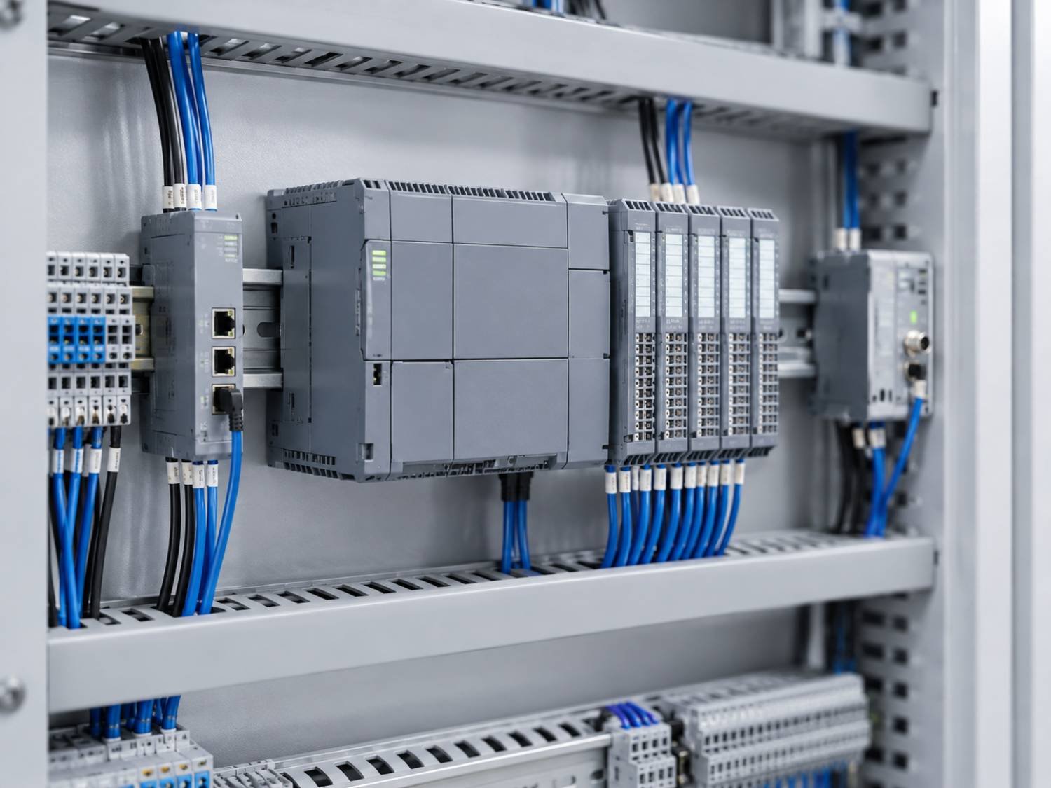
Industrial control equipment can contain different boards for processing, measurement, interfaces and connection. Identify the particular board and its installation conditions before defining the construction and acceptance requirements.
Bare-Board Manufacturing Scope
PCBELEC manufactures the specified printed circuit board. Circuit design, component sourcing, assembly and equipment-level validation are separate from the bare-board fabrication scope described here.
Review Manufacturing Capabilities →-
01
PLC & Controller Boards
Board requirements for programmable logic controllers, processing and associated control functions.
Confirm: stackup, interfaces, hole structure, mounting and specified electrical features.
-
02
I/O, Sensor & Measurement Boards
Bare-board requirements for input/output, sensing, signal interfaces and measurement electronics.
Confirm: material, layer arrangement, connections, critical geometry and verification requirements.
-
03
Motion & Drive-Control Boards
Board requirements within motion and drive equipment, with control functions and power-related circuits identified separately.
Confirm: board role, copper, interconnects, spacing and mechanical interfaces.
-
04
Industrial Communication & HMI Boards
Board constructions for industrial communication, gateways and human-machine interface electronics.
Confirm: interface features, board format, mounting and any specified impedance requirements.
-
05
Backplanes & Interconnection Boards
Board requirements for connections between control, interface and other specified modules.
Confirm: thickness, connector locations, finished holes, alignment and specified press-fit conditions.
Installation Conditions & Board Requirements
Translate Installation Conditions into Board Requirements
State where the board will be installed and which conditions apply to it. Provide the resulting material, construction and acceptance requirements rather than relying only on terms such as “rugged” or “industrial grade.”
Swipe horizontally if needed to view all installation requirements.
| Installation / Operating Input | Information to Provide | Scope to Confirm |
|---|---|---|
| Temperature Conditions | Relevant operating and storage conditions, exposure duration or cycling requirements, and the governing customer specification. | Material and construction requirements, the object to be evaluated and any separately required evidence. Do not use a material label alone as the board's temperature rating. |
| Humidity, Condensation & Contamination | Whether the board is enclosed, the expected exposure and any specified material, cleanliness or evaluation requirements. | What belongs in bare-board fabrication and what belongs to later assembly protection, enclosure design or equipment evaluation. |
| Vibration, Shock & Mounting | Mounting locations, hole geometry, board support conditions, relevant mechanical requirements and the applicable evaluation method. | Critical dimensional requirements and any agreed additional evaluation. Bare-board inspection does not establish complete-equipment vibration or shock performance. |
| Electrical Spacing & Insulation | Customer-defined spacing, slot, material and insulation requirements, with the applicable drawing and acceptance criteria. | Fabrication features and tolerances required by the design. System safety analysis and equipment compliance remain separate from board manufacturing. |
| Installation & Connection Interfaces | Outline, thickness, datums, mounting holes, connector positions and specified finished-hole or press-fit requirements. | Dimensions and measurement conditions for the manufactured board. Confirm any mating-interface requirements in the approved fabrication package. |
| Environmental Evaluation | Test object, document and revision, method, fixtures, sample quantity, acceptance limits and required report format. | Who performs the evaluation, whether additional work is accepted and which records are included in the delivery scope. |
Specify any additional environmental evaluation during inquiry. It is not assumed to be included with routine bare-board fabrication and inspection.
Explore PCB Materials →Construction, Materials & Critical Features
Select the Construction for the Specified Design
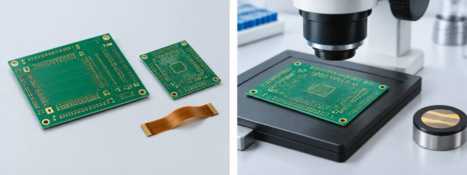
Match the board construction to the actual circuit, connections and installation requirements. Industrial control equipment does not automatically require HDI, heavy copper or a particular laminate.
Review the complete combination of materials, copper, holes and mechanical features rather than treating each capability as independent of the rest of the design.
Swipe horizontally if needed to compare all construction options.
| Construction / Feature | When to Evaluate | What to Define | Related Resource |
|---|---|---|---|
| Rigid & Multilayer | Control, interface or measurement designs with defined routing, reference layers and mechanical board formats. | Stackup, material grade, dielectric thicknesses, copper, finished thickness and hole structure. |
Rigid PCB →
Multilayer PCB → |
| Backplane Construction | Boards connecting specified modules through a defined connector and interconnection arrangement. | Board thickness, connector positions, hole geometry, finished-hole tolerances and any specified press-fit requirements. | Manufacturing Capabilities → |
| Specified Copper / Power-Related Features | Designs that call for increased copper or other defined conductor and connection features. | Finished copper, conductor geometry, spacing, interconnects and the associated acceptance requirements. | Heavy Copper PCB → |
| HDI, Where Required | Dense layouts that specify microvias, build-up interconnects or defined fine features. | Build-up sequence, via spans, pad geometry, dielectric system and any filling or capping requirements. | HDI PCB → |
| Flexible & Rigid-Flex | Designs specifying flexible regions, flexible connections or integrated rigid and flexible sections. | Region definitions, thicknesses, bend conditions, coverlay, stiffeners and rigid-to-flex transitions. |
Flexible PCB →
Rigid-Flex PCB → |
Listed constructions are options for project review, not universal industrial requirements. Confirm the complete design and any additional evaluation scope before manufacturing release.
Quality, Acceptance & Required Records
Define Acceptance and Required Quality Records
PCBELEC provides microsection reports with every order, offers 100% impedance testing and supports IPC Class 3 requirements. Define the acceptance criteria and records for the actual industrial PCB order.
-
01
Microsection Reports for Every Order
Each order includes a microsection report. Identify any additional requirements for sample locations, measurements, acceptance limits or customer report format.
-
02
100% Impedance Testing
Provide the specified targets, tolerances and structures. Confirm the test approach, coverage definition and required reporting for the accepted design.
-
03
IPC Class 3 Support
Specify the governing board standard, revision, acceptance class and customer additions. Class 3 support does not mean every industrial order defaults to Class 3.

Connect the Evidence to the Released Build
Keep the drawing, fabrication data and required records aligned with the same approved revision. Resolve acceptance questions before manufacturing release.
-
01
Governing Requirements
Identify the applicable standard, revision, class and customer additions rather than relying only on “industrial quality.”
-
02
Critical Features & Limits
Define critical dimensions, construction features, electrical requirements and the agreed verification or reporting conditions.
-
03
Identification & Records
State the required board, revision or lot references, marking conditions and documents needed with the delivered order.
-
04
Approved Changes
Record accepted engineering answers, substitutions and deviations. Define which changes require approval before release.
Identify additional inspection and documentation requirements during inquiry. Confirm their accepted scope before production rather than assuming every evaluation is included.
Explore Testing & Inspection →Repeat Manufacturing & Change Control
Keep Repeat Orders Aligned with the Approved Build
Give each order a clear manufacturing baseline. Keep the approved files, construction and acceptance conditions aligned as the project moves from evaluation boards to repeat production.
-
01
Define the Evaluation Build
Identify the initial revision, construction, quantity and acceptance scope. Mark preliminary information and resolve manufacturing questions before release.
-
02
Establish the Approved Definition
Carry accepted evaluation changes into the released drawings and fabrication data. Record the approved stackup, materials, critical features and required records.
-
03
Confirm Each Repeat Order
Reference the required board and revision, then confirm quantity, panel format, identification, packaging, delivery conditions and documentation requirements.
-
04
Review Changes Before Release
Identify proposed substitutions or construction changes explicitly. Confirm any required approval, additional evaluation and effect on the accepted quotation before manufacturing release.
Include These Details with Your Inquiry
Files & Revision
Gerber and drill data, fabrication drawings and the required released or preliminary revision.
Construction & Conditions
Stackup, materials, copper, thickness, special features and customer-defined installation requirements.
Acceptance & Records
Governing specifications, critical tolerances, verification conditions and required identification or reports.
Quantity & Supply Plan
Order quantity, delivery format, packaging, destination, target dates and any planned repeat orders.
Industrial Control PCB Manufacturing FAQ
Clarify the Requirements Before You Order
Practical answers about industrial board specifications, installation conditions, acceptance and repeat manufacturing.
Need a project-specific answer?
sales@pcbelec.comWhat makes a PCB suitable for industrial control equipment?
Suitability depends on the board function, installation conditions, specified construction and acceptance requirements. Identify whether the board handles control, measurement, interfaces, power-related functions or interconnection.
“Industrial grade” alone is not a complete specification. Provide the actual files, material and construction requirements, together with any additional evaluation criteria.
Do industrial control PCBs always require high-Tg materials?
No. The required material follows the actual design, manufacturing and installation requirements. Specify the grade, approved list or measurable criteria rather than assuming one material category fits every industrial board.
Tg alone does not define the complete board's operating conditions or lifetime. Identify the other required properties and any evaluation scope separately.
Do all industrial PCBs need IPC Class 3?
No. The acceptance class should be stated in the governing project requirements rather than inferred from the industrial application label.
PCBELEC supports IPC Class 3 requirements. Specify the applicable board standard, revision, class and customer additions for the actual order.
What environmental information should I provide?
Identify the board's installation location and relevant temperature, humidity, contamination, vibration or shock conditions. Include the material, construction and acceptance requirements derived from the design.
If additional evaluation is required, define the test object, method, fixtures, sample quantity, acceptance limits and responsibility. It is not assumed to be included in routine fabrication.
What should be specified for backplanes and press-fit connections?
Provide the approved thickness, connector positions, datum references, hole geometry and finished-hole tolerances, together with the applicable interface specification.
Identify critical dimensions and required measurements explicitly. Do not rely on a general backplane description to define every connector or press-fit condition.
Can flexible circuits be used in moving industrial equipment?
A flexible circuit intended for moving equipment needs a design and evaluation scope defined for that movement. Distinguish installation bending from repeated operation rather than assuming the same conditions apply.
Provide bend locations, movement conditions, stackup, coverlay, stiffeners and connection details. A generic flexible PCB label does not establish a guaranteed cycle life.
How should repeat orders and material changes be handled?
Reference the required board, revision and approved construction. Confirm quantity, delivery format and required records for each order.
State substitution restrictions and change-approval conditions in advance. For planned repeat supply, include the expected schedule and any material-continuity requirements so the scope can be reviewed.
Does PCBELEC provide design, assembly or equipment-level testing?
PCBELEC focuses on custom bare PCB manufacturing. The service described here covers the agreed fabrication, inspection and delivery records, not circuit design, component sourcing, assembly or equipment-level validation.
For PCB assembly inquiries, use the PCBJHY referral in the site footer. Any additional bare-board evaluation must be separately defined and accepted.