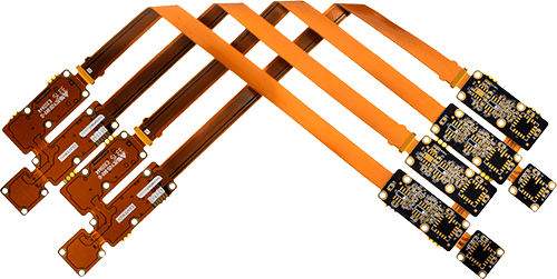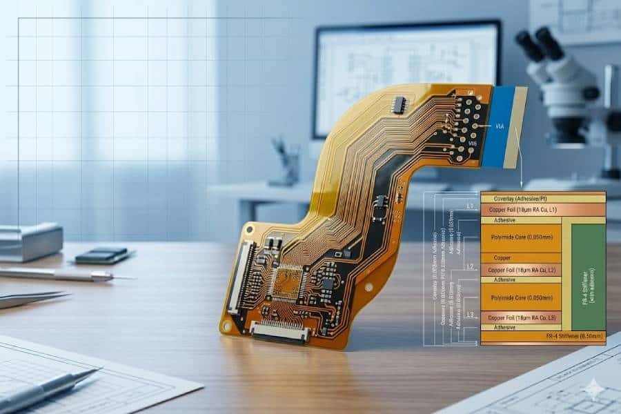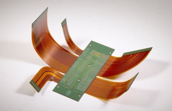
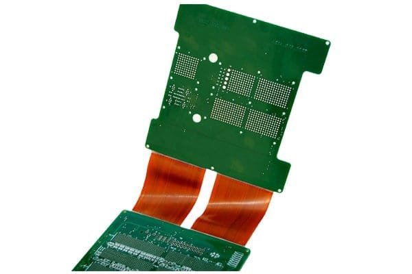
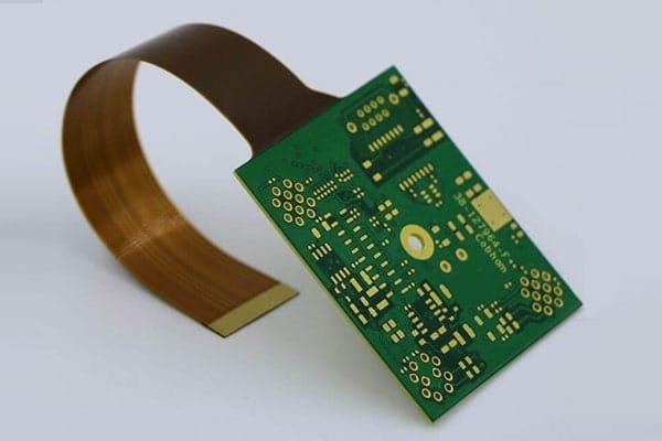
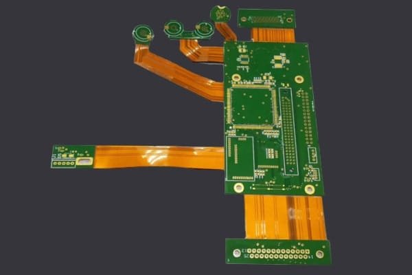
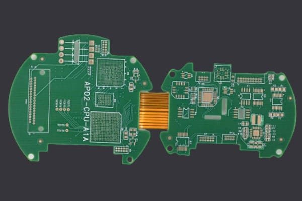
Complete Rigid-Flex Capability
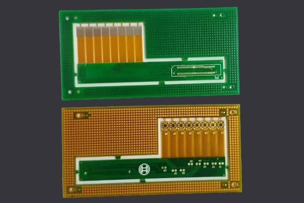
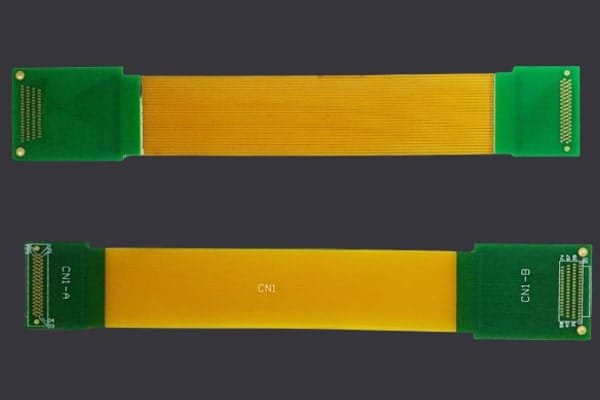
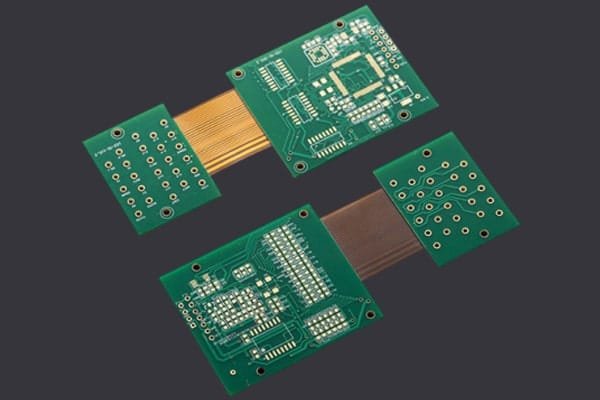
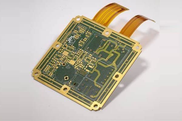
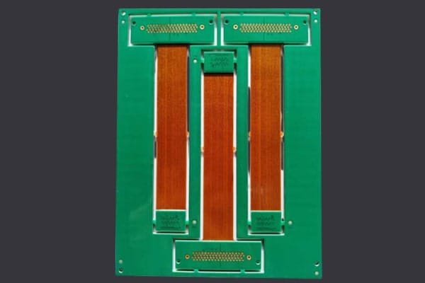
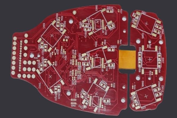
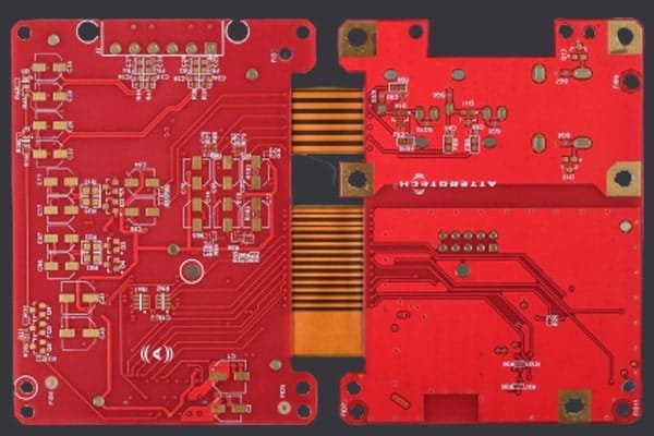
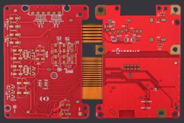
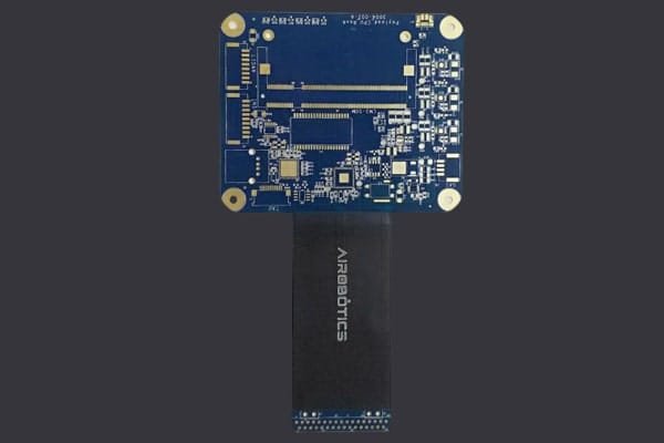
JHYPCB can manufacture 1–12 layer rigid-flex PCB with polyimide and FR4 materials, supporting advanced features such as blind and buried vias, controlled impedance and stiffeners.


DFM Support and Free Design Check
Before fabrication, our engineers perform free DFM checks on your Gerber files to verify stackup, rigid‑to‑flex transitions, coverlay layers and manufacturability, helping you avoid costly design issues.

Quick-Turn Prototype and Low MOQ
JHYPCB offers quick‑turn rigid-flex PCB prototype services with no minimum order quantity, allowing you to validate your design with as few as one prototype before moving to mass production.

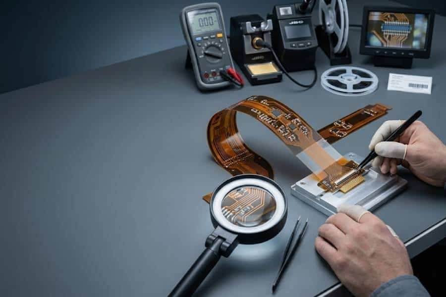
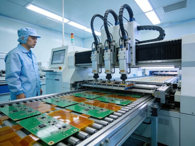
One-Stop Fabrication and Assembly
With in‑house fabrication, components sourcing, SMT and through‑hole assembly, and full testing, JHYPCB delivers end‑to‑end rigid-flex PCB solutions under one roof.

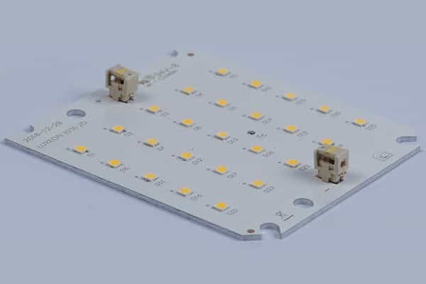
Automotive Rigid-Flex PCB Solutions
We support automotive-grade rigid-flex PCB designs for control units, displays, sensors and LED lighting, with strong vibration resistance and stable performance over a wide temperature range.

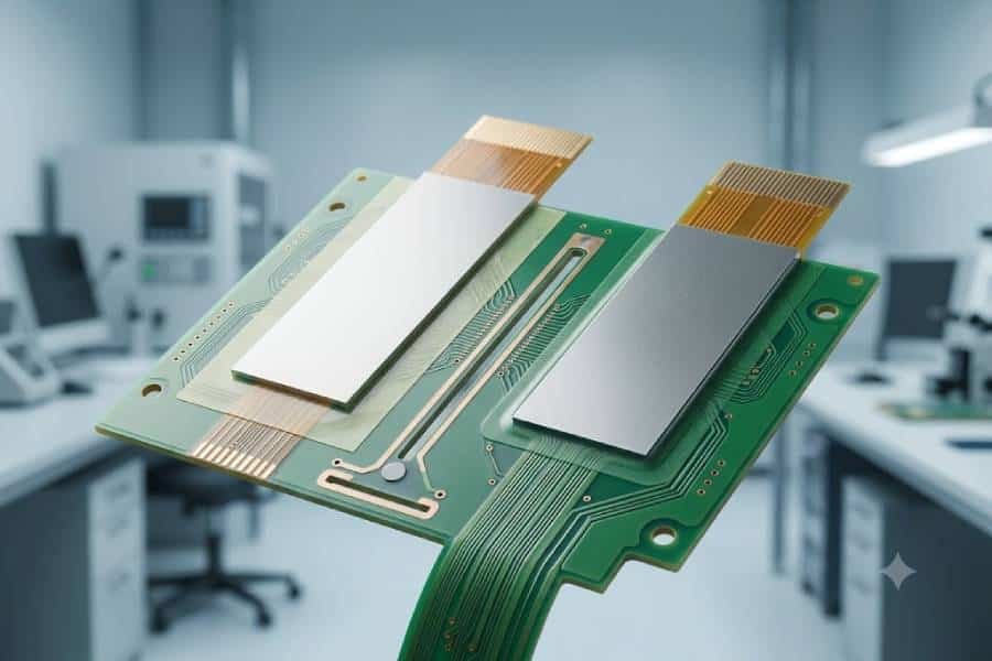
Medical Rigid-Flex PCB Solutions
For medical devices, JHYPCB provides clean, high-reliability rigid-flex PCB fabrication and assembly, helping you meet strict safety and regulatory requirements.

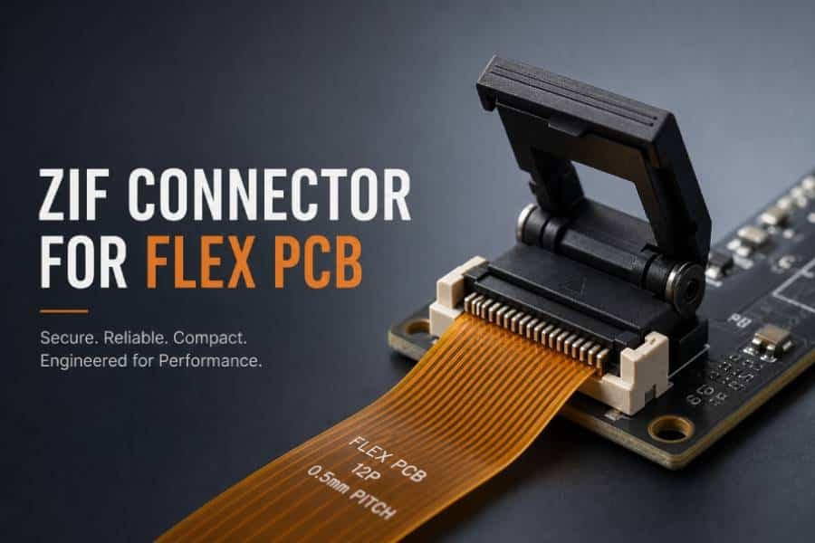
Communication & Networking Solutions
Our rigid-flex PCB solutions for smartphones, RF modules and network equipment focus on controlled impedance, signal integrity and compact layouts for high-speed data transmission.

Aerospace & Industrial Solutions
JHYPCB manufactures rigid-flex PCB for aerospace and industrial control applications that require lightweight construction, long service life and reliable performance in harsh environments.
ISO, UL and RoHS Compliance
JHYPCB operates under ISO-certified quality management and complies with UL and RoHS requirements to support global customers in different industries.
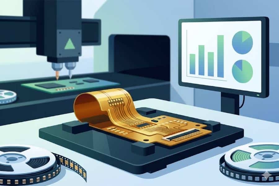
Comprehensive Electrical and Functional Testing
Depending on your needs, we can provide flying probe test, in‑circuit test, AOI, X‑ray inspection and burn‑in testing for rigid-flex PCB assemblies.
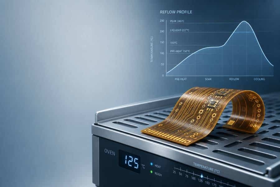
Strict Process Control and Traceability
Key processes such as drilling, plating, etching and lamination are closely monitored and recorded to maintain stable quality and full traceability for your projects.
Prototype to Mass Production Consistency
The same engineering and process standards are used for prototypes and volume orders, helping you scale from evaluation to mass production with minimal risk.