

Lead-Free PCB Assembly
The global electronics industry’s shift to lead-free soldering is no longer optional — it’s a regulatory, environmental, and commercial necessity. Here’s what you need to know.
- Lead-free SMT, through-hole, and mixed assembly
- RoHS-compliant materials and process control
- Prototype, low-volume, and quick-turn support
- Turnkey and consigned assembly options
Why Lead-Free Matters Now
The elimination of lead from electronics manufacturing was not a voluntary industry initiative — it was driven by regulation. Understanding the regulatory landscape helps you make informed compliance decisions for your products and target markets.
| Regulation | Year | Region | What It Means |
|---|---|---|---|
| RoHS 1 (Directive 2002/95/EC) | 2003 | European Union | First restriction of 6 hazardous substances including lead (Pb) in electronic equipment. Forced the industry to develop lead-free solder alternatives. |
| RoHS 2 (Directive 2011/65/EU) | 2011 | European Union | Expanded scope to all EEE (electrical and electronic equipment). Made CE marking contingent on RoHS compliance — non-compliant products cannot bear the CE mark. |
| RoHS 3 (Directive 2015/863) | 2015 | European Union | Added 4 phthalates to the restricted list. Mandated compliance by July 2019. Currently the strictest global standard. |
| China RoHS (ACPEIP) | 2007 | China | Requires disclosure of hazardous substances in electronic products sold in China. Different from EU RoHS — uses labeling system rather than outright ban. |
| California RoHS (SB20) | 2007 | USA (California) | Restricts lead in covered electronic devices sold in California. Other US states have followed with similar legislation. |
Lead-Free Reliability Challenges
Lead-free soldering is technically proven and widely adopted — but it is not identical to tin-lead soldering. Engineers transitioning to lead-free should understand three key reliability challenges that differ from traditional leaded assembly.

Tin Whisker Formation
Pure tin and high-tin lead-free alloys (SAC305 is 96.5% tin) can grow conductive crystalline “whiskers” over time — microscopic metal filaments that can bridge adjacent pads and cause short circuits. Whiskers are caused by compressive stress in the tin plating, thermal cycling, and mechanical vibration. Risk mitigation: use Ni-doped alloys (SN100C), conformal coating, and avoid pure tin plating on critical surfaces.
Thermal Fatigue in Cycling
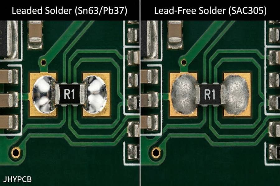
Lead-free SAC305 solder joints are more brittle than tin-lead joints. In applications with repeated thermal cycling (automotive engine compartments, outdoor electronics, aerospace), SAC305 joints can develop cracks faster than Sn63Pb37 joints. The higher modulus of lead-free solder means less plastic deformation absorption, transferring stress to the joint interface.
Voiding in BGA Joints
Lead-free solder paste generates more gas during reflow than tin-lead paste, leading to higher voiding rates in BGA and QFN solder balls. Voids reduce thermal transfer and mechanical strength. IPC-7095 allows up to 25% voiding, but high-reliability applications (automotive, medical) often require <10%. Void reduction requires optimized reflow profile, paste selection, and vacuum reflow for critical applications.
Cost Impact of Switching to Lead-Free Assembly
Switching from tin-lead to lead-free assembly affects your project budget in several ways beyond just the solder material itself. Understanding these cost factors helps you budget accurately and avoid surprises during production.
| Cost Factor | Leaded (Sn63Pb37) | Lead-Free (SAC305) | Cost Difference |
|---|---|---|---|
| Solder Paste Material | Tin-lead paste | SAC305 paste (contains 3% silver) | +15–25% per kg |
| Wave Solder Alloy | Sn63Pb37 bar | SAC305 or SN100C bar | +20–30% per kg |
| Reflow Energy | Peak 210–230°C | Peak 240–260°C (+30°C) | +10–15% energy cost per reflow cycle |
| Component Compatibility | Most components rated for leaded temps | Components must be rated for 260°C peak | Some specialized components cost more or have longer lead times |
| Rework & Repair | Easier — lower melt temp, better wetting | Harder — higher melt temp, faster oxidation | +30–50% rework labor time |
Frequently Asked Questions About Lead-Free PCB Assembly
"Lead-free" in PCB assembly means all solder materials used contain less than 0.1% lead (Pb) by weight in any homogeneous material, as defined by the EU RoHS Directive. Solder alloys are typically tin-based with additions of silver and copper, such as SAC305 (Sn96.5/Ag3.0/Cu0.5), which contains zero lead.
Lead is a heavy metal that causes neurological damage, particularly in children. When electronic waste is landfilled or improperly recycled, lead leaches into soil and groundwater. The EU RoHS Directive (2003) was the first major regulation to restrict lead in electronics, driven by the growing volume of e-waste and its environmental and public health impact.
The three primary reliability challenges are: (1) tin whisker formation — microscopic conductive filaments that can cause short circuits; (2) thermal fatigue — lead-free joints are more brittle and can crack under repeated thermal cycling; (3) voiding — lead-free solder paste generates more gas during reflow, creating voids in BGA joints. All three are manageable with proper alloy selection, reflow optimization, and conformal coating.
Lead-free PCB assembly typically costs 15–30% more than tin-lead assembly, primarily due to silver content in SAC305 solder (3% silver), higher reflow temperatures increasing energy costs, and more difficult rework. Using lower-silver alloys like SAC307 or SN100C can reduce the material cost premium by 5–10%.
Yes. Lead-free solder joints have been extensively validated through industry testing including IPC-TM-650 thermal cycling, JESD22-A104 temperature cycling, and drop testing per JESD22-B111. Lead-free assemblies have been deployed in automotive, aerospace, and medical applications for over 15 years. The key is using the right alloy for the application and following IPC-A-610 Class 2 or 3 inspection standards.
No. RoHS exemptions exist for specific applications including military/aerospace equipment, certain medical implants, high-reliability servers, and some leaded solder used in specific glass and ceramic components. However, exemptions are being progressively narrowed — check the current EU RoHS exemption list for your specific application. Products sold in the EU, China, and California without an applicable exemption must use lead-free assembly.