Mixed Technology PCB Assembly
Combining SMT and Through-Hole technologies on a single PCB — when your design demands both surface-mount precision and through-hole mechanical strength.
When to Choose Mixed-Technology Assembly
Not every PCB needs a single assembly method. Many practical designs call for both SMT for compact, high-density areas and through-hole (THT) for components that require mechanical strength or power handling. Choosing mixed-technology assembly is a strategic decision based on component type, board function, and production volume.
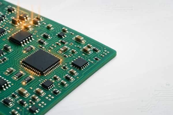
High-density + power components on one board
Your design has SMD-based control circuitry alongside bulky connectors, relays, transformers, or heat-sinked power devices that need THT soldering for mechanical reliability.
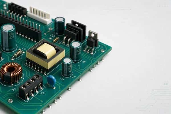
Legacy + modern component mix
Some critical components are only available in through-hole packages (e.g., certain transformers, capacitors, high-power MOSFETs), while the rest of your BOM uses SMD packages.
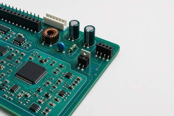
Prototyping with design flexibility
During prototyping, mixed-technology lets you place through-hole headers for testing/debugging access while SMT handles the production-intent circuitry.
Key takeaway: If your BOM contains more than 85–90% SMD components and only a few THT parts (connectors, transformers, large capacitors), mixed-technology is almost always the most cost-effective choice — not an all-THT approach.
Mixed-Technology Assembly Process Flow
The manufacturing sequence for mixed-technology boards is not arbitrary. SMT is always processed first, followed by through-hole assembly. This order is dictated by the thermal characteristics of solder paste and the physical constraints of wave/selective soldering.
| Step | Process | Purpose |
|---|---|---|
| 1 | Solder Paste Printing | Stencil-print solder paste onto SMD pads only; THT holes remain open |
| 2 | SMD Pick & Place + Reflow | Surface-mount components are placed and reflow-soldered; THT components are not yet on the board |
| 3 | THT Component Insertion | Through-hole components are inserted manually or by automated axial/radial inserters |
| 4 | Wave or Selective Soldering | The bottom side passes through wave soldering (for all-THT bottom) or selective soldering (to avoid reflowing nearby SMD joints) |
| 5 | AOI + ICT + Functional Test | Automated optical inspection covers both SMT and THT joints; in-circuit and functional tests verify full board integrity |
Why SMT first? Reflow soldering temperatures (240–260°C) would remelt wave-soldered THT joints. By completing SMT first and THT second, the process avoids thermal interference and ensures joint integrity for both technologies.
DFM Design Rules for Mixed-Technology PCBs
Designing a mixed-technology board requires planning for both SMT and THT manufacturing constraints simultaneously. The following rules prevent the most common defects — solder bridges, insufficient hole fill, and reflow interference.
-
Maintain 3mm clearance from THT to nearest SMD:
Keep through-hole component leads at least 3mm away from SMD pads on the wave-solder side to prevent solder bridging during wave/selective soldering. -
Use solder mask between THT holes and SMD pads:
Apply solder mask dams (SMD) between adjacent through-hole vias and surface-mount pads to restrict solder flow and prevent bridges. -
Orient THT components parallel to wave direction:
Through-hole components on the wave-solder side should be oriented parallel to the board's travel direction through the wave to ensure uniform solder fill. -
Add thermal relief pads for large copper areas:
Large copper pours connected to THT pads create thermal sinks that prevent proper solder flow. Use thermal relief (spoke) connections instead. -
Avoid placing SMD on the wave-solder side when possible:
If SMDs must be on the bottom side, use adhesive (glue) to secure them before wave soldering, and verify they survive wave thermal exposure.
⚠️ Common pitfall: Forgetting to add solder mask between a THT connector pad and a nearby SMD resistor is the #1 cause of solder bridges in mixed-technology boards. Always run a DFM check focusing on THT-to-SMD proximity.
Frequently Asked Questions
Mixed technology PCB assembly combines surface-mount technology (SMT) and through-hole technology (THT) on a single printed circuit board. SMT handles compact, high-density components while THT is used for components requiring mechanical strength, such as connectors, transformers, and large capacitors.
Yes, mixed-technology is typically 15–30% more expensive than pure SMT due to the additional through-hole insertion and wave/selective soldering steps. However, it is more cost-effective than all-THT when only a few components require through-hole mounting.
Not always. Certain components — high-power relays, transformers, large electrolytic capacitors, and heavy connectors — are not available or not reliable in SMD packages. For these designs, mixed-technology is the only practical solution.
SMT is always processed first: solder paste printing, SMD pick-and-place, and reflow soldering. Through-hole components are inserted afterward, followed by wave soldering or selective soldering. This order prevents reflow temperatures from remelting THT joints.
Selective soldering uses a programmable mini-wave nozzle to solder individual THT joints without affecting nearby SMD components. It is used when SMD parts on the bottom side would be damaged by full wave soldering, making it essential for dense mixed-technology boards.
PCBELEC provides mixed-technology assembly through our partner facility JHYPCB. For SMT-focused assembly, visit our SMT assembly page. For through-hole assembly, visit our THT assembly page. Both options are available with full DFM review and IPC-A-610 inspection.