Table of Contents
Choosing the right PCB substrate material is one of the most critical decisions in the entire electronics design and manufacturing process. The substrate directly impacts electrical performance, thermal management, signal integrity, mechanical reliability, and — most importantly — the success of your SMT assembly process.
Many engineers focus heavily on component selection and schematic design while treating the PCB material as a secondary consideration. This approach often leads to costly issues later: excessive signal loss, overheating, board warping, poor solder joint reliability, or even complete redesigns during prototyping or mass production.
Today’s electronic products are pushing the boundaries of performance:
- 5G, 6G, and mmWave applications demand ultra-low loss materials
- AI servers and high-speed data centers require excellent signal integrity at multi-gigabit speeds
- High-power LED lighting and power electronics need superior thermal dissipation
- Wearable devices and medical electronics call for flexible, durable, and lightweight solutions
- Automotive and industrial electronics must survive harsh environments with wide temperature ranges and strong vibration
Engineers frequently face the same dilemma: Should I stick with cost-effective FR4, upgrade to Rogers high-frequency laminates, choose Aluminum MCPCB for heat dissipation, or consider hybrid stack-up designs?
This comprehensive guide answers all these questions. We will provide an in-depth comparison of FR4, Rogers, Aluminum/Copper Core PCBs, Polyimide Flex, Ceramic, and other advanced materials, complete with performance data, selection matrices, real-world applications, and — crucially — detailed SMT assembly considerations for each material type.
Whether you are a hardware design engineer, product developer, or sourcing professional, this guide will help you select the optimal PCB substrate that balances performance, manufacturability, cost, and reliability.
Why Substrate Choice Matters
The choice of PCB substrate material is far more than a simple procurement decision — it is a foundational factor that determines the electrical, thermal, mechanical, and long-term reliability performance of your entire product.
Selecting the wrong material can lead to signal degradation, excessive heat buildup, mechanical failures during SMT assembly, or poor field reliability. Conversely, choosing the right substrate helps you achieve optimal performance while controlling costs and ensuring smooth manufacturability.
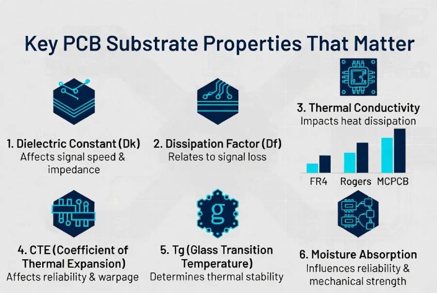
Here are the key material properties that engineers must evaluate:
1. Dielectric Constant (Dk) and Signal Integrity
The dielectric constant (Dk) measures how much a material slows down electrical signals. Lower Dk values are critical for high-frequency and high-speed designs because they enable faster signal propagation and reduce signal delay.
- In 5G, mmWave, and high-speed digital applications, even small variations in Dk can cause impedance mismatch and signal distortion.
2. Dissipation Factor (Df) – Signal Loss
Also known as loss tangent, Df indicates how much signal energy is lost as heat in the material. Lower Df materials (such as Rogers laminates) are essential for RF, microwave, and high-frequency applications where minimizing insertion loss is critical.
3. Thermal Conductivity
This determines how efficiently the material transfers heat away from hot components. Standard FR4 has poor thermal conductivity (~0.3 W/m·K), while Aluminum and Copper core PCBs offer significantly higher values, making them ideal for high-power applications.
4. Coefficient of Thermal Expansion (CTE)
CTE describes how much the material expands or contracts with temperature changes. A mismatch between the substrate CTE and components can cause solder joint fatigue, via cracking, or board warping — especially problematic during SMT reflow soldering and in harsh operating environments.
5. Glass Transition Temperature (Tg) and Decomposition Temperature (Td)
- Tg: The temperature at which the material shifts from rigid to rubbery state.
- Td: The temperature at which the material begins to chemically break down.
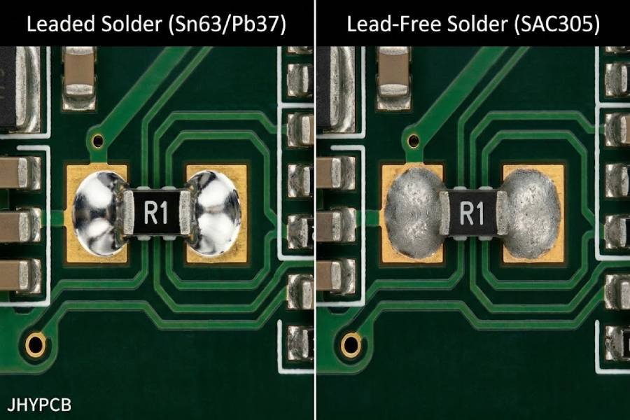
Higher Tg and Td materials provide better thermal stability during lead-free soldering processes (which typically peak above 260°C).
6. Other Critical Factors
- Moisture Absorption
- Mechanical Strength & Flexural Modulus
- Flammability Rating (UL94)
- Cost and Availability
Consequences of Poor Material Selection
- Excessive signal loss leading to poor wireless performance
- Thermal runaway or reduced component lifespan
- Board warpage and high SMT defect rates
- Field failures due to CTE mismatch or delamination
- Increased overall project cost from redesigns or yield loss
In today’s competitive market, where products must deliver higher performance in smaller form factors and harsher environments, the substrate is no longer just a “board” — it is a performance enabler.
Understanding these fundamental properties is the first step toward making informed decisions. The following sections will dive deep into the most common PCB substrate materials and provide clear guidance on when to use each.
Deep Dive into Common PCB Substrate Materials
FR4 – The Versatile Industry Standard
FR4 remains the most widely used PCB substrate material in the electronics industry, and for good reason. It is a glass-reinforced epoxy laminate that offers an excellent balance of performance, cost, and manufacturability.
Key Properties:
- Dielectric Constant (Dk): 4.2 – 4.8 (varies with frequency and temperature)
- Dissipation Factor (Df): 0.015 – 0.025
- Thermal Conductivity: ~0.25 – 0.35 W/m·K
- Tg (Glass Transition Temperature): 130–180°C (High-Tg variants available)
- CTE (Z-axis): 50 – 70 ppm/°C
- Cost: Lowest among rigid PCB materials
Advantages:
- Excellent mechanical strength and dimensional stability
- Good electrical insulation
- Mature processing technology — compatible with standard SMT assembly lines
- Cost-effective for high-volume production
- Widely available in various thicknesses and copper weights
Limitations:
- Higher signal loss at frequencies above 1–2 GHz
- Dk is less stable across frequency and temperature ranges
- Poor thermal conductivity — not suitable for high-power applications
- Higher Z-axis CTE can lead to reliability issues in harsh environments
Typical Applications:
- Consumer electronics
- General industrial control
- Low-to-medium speed digital circuits
- Power supplies (non-high-power)
SMT Assembly Notes: FR4 is highly compatible with standard lead-free reflow profiles. High-Tg versions are recommended for complex boards with large BGAs or when multiple reflow cycles are expected.
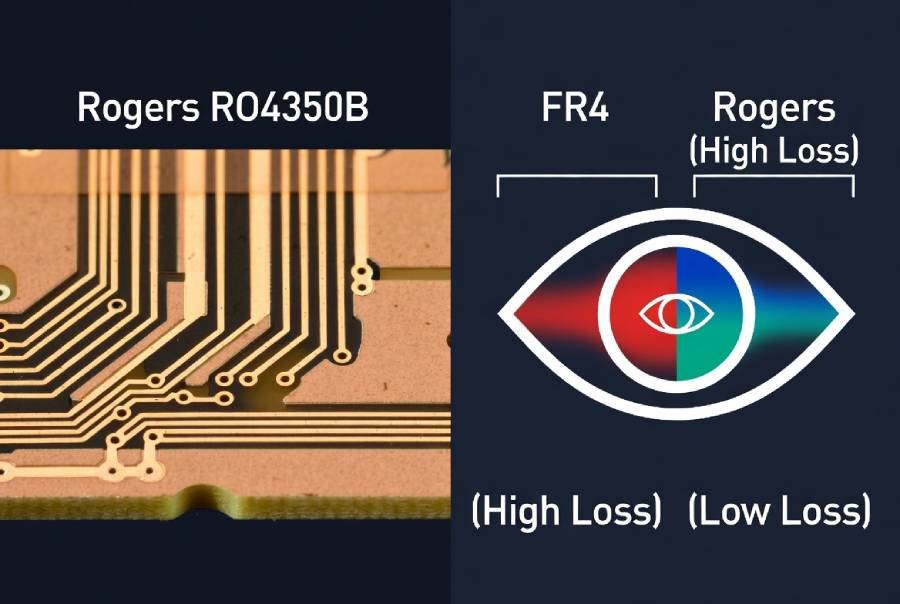
Rogers High-Frequency Laminates (RO4000 Series, especially RO4350B)
When standard FR4 can no longer meet the electrical requirements, Rogers materials — particularly the RO4000 Series — become the go-to solution for high-frequency and high-speed designs.
Key Properties (Rogers RO4350B):
- Dielectric Constant (Dk): 3.48 ± 0.05 (very stable)
- Dissipation Factor (Df): 0.0037 @ 10 GHz
- Thermal Conductivity: 0.69 W/m·K
- Tg: >280°C
- CTE (Z-axis): 32 ppm/°C (much closer to copper)
- Moisture Absorption: Very low (~0.05%)
Advantages:
- Significantly lower signal loss at RF and microwave frequencies
- Stable Dk over wide frequency and temperature ranges → excellent impedance control
- Better thermal performance than FR4
- Compatible with standard FR4 processing (easier than PTFE materials)
- UL 94 V-0 rating
Limitations:
- Higher material cost (typically 6–12x FR4 depending on configuration)
- Slightly more challenging to process than standard FR4
Typical Applications:
- 5G base stations and antennas
- RF and microwave circuits
- Automotive radar (77GHz)
- High-speed digital designs (10Gbps+)
- Aerospace and defense systems
SMT Assembly Notes: Rogers materials handle lead-free soldering temperatures very well due to high Tg. However, proper pre-baking is important to remove any absorbed moisture.
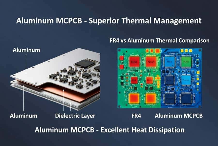
Metal Core PCBs (MCPCB) – Aluminum and Copper Base
Metal Core PCBs (MCPCBs) are designed primarily for thermal management. They incorporate a metal core (typically aluminum or copper) that acts as a heat sink, dramatically improving heat dissipation compared to standard FR4.
Key Properties:
- Thermal Conductivity: 1.0 – 3.0 W/m·K (effective), with the aluminum core itself exceeding 200 W/m·K
- Dielectric Layer Thickness: Usually 75–150 μm with high thermal conductivity filler
- CTE: Aluminum core ≈ 20–24 ppm/°C (better match with many components than FR4’s Z-axis)
- Mechanical Strength: Much higher rigidity and structural stability
Aluminum Core vs Copper Core:
- Aluminum MCPCB: Most common choice — lightweight, cost-effective, excellent thermal performance for most applications.
- Copper Core MCPCB: Superior thermal conductivity and heat spreading, used in ultra-high power or where maximum heat dissipation is required. Heavier and significantly more expensive.
Advantages:
- Superior heat dissipation, reducing junction temperatures by 20–50°C in high-power designs
- Improved reliability and lifespan of power components and LEDs
- Enhanced mechanical durability and vibration resistance
- Better thermal stability during operation
Limitations:
- Limited to lower layer counts (1–4 layers typical, multi-layer possible but complex)
- Not ideal for high-frequency RF signals due to the metal core
- Heavier than FR4
- Higher material and processing cost than standard FR4
Typical Applications:
- High-power LED lighting (street lights, automotive, horticulture)
- Power supplies, DC-DC converters, and motor drivers
- Automotive electronics (headlights, battery management)
- Audio amplifiers and industrial power modules
SMT Assembly Notes: Due to high thermal mass, aluminum MCPCBs require optimized reflow profiles — often higher peak temperatures or adjusted soak times. They cool down faster after the reflow zone, so precise temperature control is essential to avoid cold solder joints or component damage. JHYPCB has extensive experience tuning profiles for MCPCBs to achieve high yield.
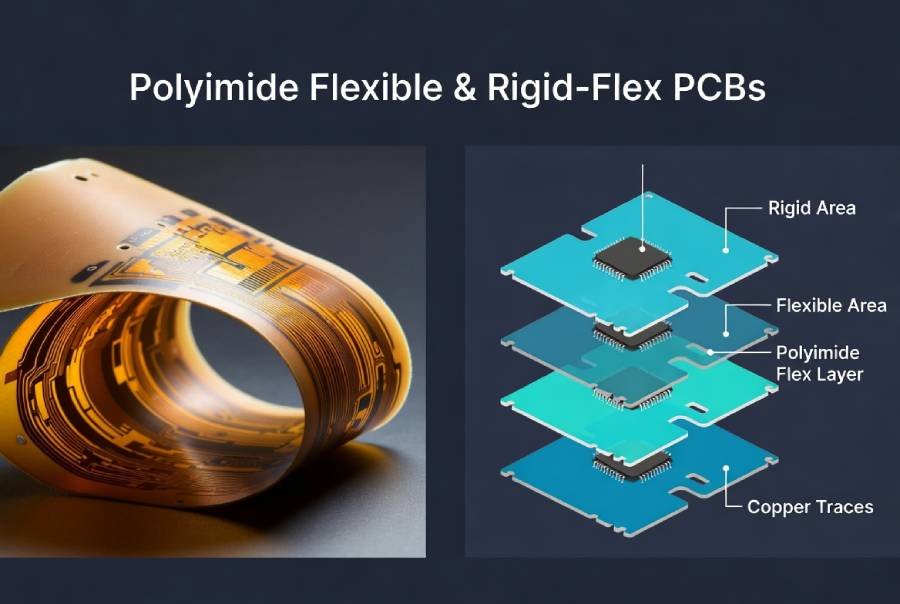
Polyimide for Flexible and Rigid-Flex Circuits
Polyimide (PI) is the dominant material for flexible PCBs (Flex) and rigid-flex PCBs. It offers exceptional flexibility, thermal stability, and mechanical durability where standard rigid materials like FR4 would fail.
Key Properties:
- Dielectric Constant (Dk): 3.2 – 3.6
- Dissipation Factor (Df): 0.001 – 0.005 (excellent for many high-speed applications)
- Thermal Conductivity: 0.1 – 0.35 W/m·K
- Tg (Glass Transition Temperature): 250–400°C+ (depending on grade)
- Operating Temperature Range: -269°C to +260°C (continuous for many grades)
- CTE: Relatively low and well-controlled
- Moisture Absorption: Very low (~0.2–0.3%)
Advantages:
- Outstanding flexibility — can withstand thousands of bending cycles
- Extreme temperature resistance (far superior to FR4)
- Excellent chemical and radiation resistance
- Good electrical properties with stable Dk/Df
- Thin and lightweight, enabling compact, space-saving designs
Limitations:
- Higher material and manufacturing cost (typically 6–12x FR4)
- More complex processing (requires specialized handling)
- Lower thermal conductivity than MCPCB — not ideal for very high-power dissipation
Typical Applications:
- Wearable devices and consumer electronics (foldable phones, smartwatches)
- Medical electronics (implantable devices, imaging equipment)
- Aerospace and defense (weight-saving, vibration resistance)
- Automotive (dashboard, cameras, sensors in tight spaces)
- Industrial equipment requiring dynamic flexing
Rigid-Flex PCB Advantage: Combines rigid FR4 or Rogers sections for component mounting with polyimide flex areas for interconnection. This solution reduces connectors, improves reliability, and saves space — increasingly popular in modern compact designs.
SMT Assembly Notes: Rigid-flex boards require careful handling to protect flex areas. Special carriers or pallets are often used during SMT. Reflow profiles must consider different thermal masses between rigid and flex zones. Pre-baking is critical to remove moisture before assembly.
Other Advanced Materials
Beyond the mainstream options, several specialized materials are used when extreme performance is required. These materials address specific challenges in ultra-high frequency, high-temperature, or ultra-reliable applications.
Ceramic Substrates
Ceramic PCBs (using materials such as Alumina (Al₂O₃), Aluminum Nitride (AlN), or Silicon Carbide) deliver exceptional thermal and electrical performance.
Key Properties:
- Dielectric Constant (Dk): 5.7 – 9.8 (depending on type)
- Dissipation Factor (Df): Extremely low (0.0002 – 0.001)
- Thermal Conductivity: 20 – 180 W/m·K (AlN is outstanding)
- CTE: Very low and closely matched to silicon (excellent reliability)
- Operating Temperature: Up to 800°C+
Advantages:
- Superior thermal dissipation and heat spreading
- Excellent high-frequency performance with minimal signal loss
- Outstanding thermal stability and mechanical rigidity
- High reliability in extreme environments
Limitations:
- Very high material and processing cost (15–30x FR4)
- Brittle material — lower mechanical shock resistance
- Limited size availability and more complex multilayer capability
Typical Applications:
- High-power RF and microwave modules
- Aerospace and defense electronics
- High-temperature sensors and downhole tools
- LED arrays requiring extreme heat management
SMT Assembly Notes: Ceramic boards demand highly controlled reflow profiles due to low thermal expansion and brittleness. Specialized fixtures are often required.
PTFE / Teflon-Based Materials
PTFE (Polytetrafluoroethylene) laminates, often reinforced with glass or ceramic fillers, are premium materials for ultra-high frequency applications.
Key Properties:
- Dielectric Constant (Dk): 2.0 – 2.6 (very low)
- Dissipation Factor (Df): 0.0002 – 0.0015 (among the lowest)
- Thermal Conductivity: 0.2 – 0.5 W/m·K
- Moisture Absorption: Extremely low
Advantages:
- Best-in-class high-frequency and millimeter-wave performance
- Minimal signal loss even above 30 GHz
- Stable electrical properties over wide frequency ranges
Limitations:
- Difficult to process (requires special plating and bonding techniques)
- Higher cost and longer lead times
- Softer material, more prone to dimensional variation
Typical Applications:
- Millimeter-wave radar and 5G/6G antennas
- Satellite communication systems
- High-end test and measurement equipment
- Aerospace radar and EW systems
High-Performance FR4 Alternatives (Megtron, Isola, Nelco)
Materials such as Panasonic Megtron6/Megtron7, Isola I-Tera, and Nelco offer a middle ground between standard FR4 and Rogers.
Key Properties:
- Lower Dk/Df than standard FR4 (typically Dk 3.2–3.8)
- Better loss performance at 10–28 Gbps+
- Good processability similar to FR4
Advantages:
- Better signal integrity than FR4 at a lower cost than Rogers
- Excellent for high-speed digital designs (PCIe, Ethernet, SerDes)
- Good availability and manufacturability
Typical Applications:
- Data center switches and servers
- High-speed networking equipment
- Automotive ADAS systems
Hybrid Stack-up Designs (The Smart Compromise)
Modern advanced PCBs often use hybrid constructions, combining different materials in one board (e.g., Rogers on high-frequency layers + FR4 on the rest, or Rogers + Megtron + standard FR4).
Advantages:
- Optimal performance where needed while controlling overall cost
- Excellent signal integrity for critical traces
- Better thermal and mechanical balance
- Widely adopted in 5G, AI servers, and high-end consumer electronics
SMT Assembly Notes: Hybrid boards require careful layer sequencing, precise registration control, and tailored reflow profiles to accommodate different thermal expansion rates of the materials.
PCB Material Selection Matrix – Quick Comparison Guide
Choosing the right PCB substrate becomes much easier when you can compare key properties side by side. The table below provides a clear, data-driven overview of the most common PCB materials used in SMT assembly.
📊 Material Comparison Table
Slide the table horizontally to view complete technical comparisons such as dielectric constant (Dk), loss factor (Df), thermal conductivity, thermal expansion coefficient, Tg, and applicable scenarios
| Material Type | Dk (Dielectric Constant) | Df (Dissipation Factor) @10GHz | Thermal Conductivity (W/m·K) | CTE (Z-axis, ppm/°C) | Tg (°C) | Relative Cost | Max Frequency (Practical) | SMT Assembly Difficulty | Best Applications |
|---|---|---|---|---|---|---|---|---|---|
| Standard FR4 | 4.2 – 4.8 | 0.015 – 0.025 | 0.25 – 0.35 | 50 – 70 | 130 – 150 | 1x | ≤ 2 GHz | Low | Consumer electronics, general industrial |
| High-Tg FR4 | 4.0 – 4.7 | 0.012 – 0.020 | 0.3 – 0.4 | 45 – 65 | 170 – 180 | 1.2 – 1.5x | ≤ 5 GHz | Low | Automotive, multi-reflow boards |
| Rogers RO4350B | 3.48 ± 0.05 | 0.0037 | 0.69 | 32 | >280 | 8 – 12x | Up to 40 GHz | Medium | 5G, RF antennas, radar, high-speed digital |
| Rogers RO4003C | 3.38 ± 0.05 | 0.0027 | 0.71 | 31 | >280 | 7 – 10x | Up to 40 GHz | Medium | RF & Microwave circuits |
| Aluminum MCPCB | N/A (Single/Double layer) | N/A | 1.0 – 2.5 | 20 – 24 | N/A | 2 – 4x | Low frequency | Medium | LED lighting, power electronics |
| Copper MCPCB | N/A | N/A | 3.0 – 4.0+ | 17 – 20 | N/A | 6 – 10x | Low frequency | Medium-High | Ultra-high power modules |
| Polyimide (Flex) | 3.2 – 3.6 | 0.001 – 0.005 | 0.1 – 0.35 | 20 – 50 | >250 | 6 – 12x | Up to 20 GHz | High | Wearables, medical, aerospace, rigid-flex |
| Ceramic (AlN / Al₂O₃) | 5.7 – 9.8 | 0.0002 – 0.001 | 20 – 180 | 4 – 7 | Extremely High | 15 – 30x | Up to 100 GHz+ | High | High-power RF, aerospace, extreme temp |
| PTFE / Teflon | 2.0 – 2.6 | 0.0002 – 0.0015 | 0.2 – 0.5 | 20 – 30 | N/A | 12 – 20x | Up to 100 GHz+ | High | mmWave, satellite, military radar |
| Megtron 6 / Isola | 3.2 – 3.7 | 0.002 – 0.008 | 0.4 – 0.6 | 40 – 55 | 180 – 200 | 3 – 5x | Up to 28 GHz | Low-Medium | Data center, high-speed networking |
Notes:
- Relative cost is for reference only and varies with board size, thickness, and volume.
- Thermal Conductivity for MCPCB refers to effective board-level performance.
- Max Frequency is practical/real-world recommendation, not theoretical limit.
How to Use This Matrix
- Budget Priority → Start with FR4 or High-Tg FR4.
- High Frequency / RF → Choose Rogers, Megtron, or PTFE.
- High Power / Heat → Select Aluminum or Copper MCPCB.
- Flexible / Space-constrained → Use Polyimide Rigid-Flex.
- Extreme Environments → Consider Ceramic or high-end Rogers.
Pro Tip: Many advanced designs today use Hybrid Stack-up (e.g., Rogers material only on critical high-frequency layers, with FR4 on the rest). This approach delivers excellent performance while keeping costs under control.
How to Choose the Right PCB Substrate: A Practical Decision Framework
Selecting the optimal PCB material doesn’t have to be complicated. By following a systematic decision-making process, you can balance performance, cost, manufacturability, and reliability effectively.
The PCB Material Selection Decision Flowchart
Here is a practical step-by-step framework engineers can use:
- Define Your Application Requirements
- What is the maximum operating frequency?
- What is the power/heat dissipation requirement?
- What environment will the product operate in? (Temperature range, humidity, vibration, etc.)
- Evaluate Electrical Needs
- Frequency ≤ 2 GHz → Standard or High-Tg FR4 is usually sufficient.
- Frequency 2–10 GHz → Consider Megtron/Isola or entry-level Rogers.
- Frequency > 10 GHz or mmWave → Rogers, PTFE, or Ceramic required.
- Assess Thermal Requirements
- High power density or LEDs → Aluminum or Copper MCPCB.
- Moderate heat → High-Tg FR4 or Rogers.
- Extreme heat → Ceramic or Metal Core with thermal vias.
- Consider Mechanical & Form Factor Needs
- Needs flexibility or bending → Polyimide Flex / Rigid-Flex.
- Needs high rigidity and strength → MCPCB or Ceramic.
- Factor in Budget and Volume
- High volume + cost sensitive → FR4 family.
- Medium volume + performance critical → Hybrid stack-up.
- Low volume / high performance → Full Rogers or specialized materials.
- Review SMT Assembly & Manufacturability
- Confirm the material is compatible with your assembly process and supplier capabilities.
- Validate with DFM Review
- Always request a professional Design for Manufacturability (DFM) analysis before finalizing the material.
Key Decision Factors Checklist
Use this checklist when evaluating PCB substrate materials:
- Electrical Performance — Frequency, signal loss tolerance, impedance control
- Thermal Management — Power dissipation, maximum junction temperature
- Environmental Conditions — Operating temperature, humidity, vibration, shock
- Mechanical Requirements — Size, weight, flexibility, rigidity
- Reliability & Lifespan — Expected product lifetime, thermal cycling
- Regulatory & Compliance — UL, RoHS, Reach, halogen-free
- Cost & Lead Time — Material cost, processing cost, MOQ
- Supply Chain — Material availability and long-term support
Recommended Materials by Application
| Application Area | Recommended Primary Material | Alternative / Hybrid Option | Key Reason |
|---|---|---|---|
| Consumer Electronics | Standard FR4 | High-Tg FR4 | Cost + sufficient performance |
| High-Speed Digital (10G+) | Megtron 6 / Isola | Rogers RO4350B | Better loss performance |
| 5G / RF Antennas / Radar | Rogers RO4350B / RO4003C | Hybrid (Rogers + FR4) | Low Df and stable Dk |
| High-Power LED Lighting | Aluminum MCPCB | Copper MCPCB | Superior thermal dissipation |
| Power Electronics / Converters | Aluminum MCPCB | High-Tg FR4 with thermal vias | Heat management |
| Wearable / Medical Devices | Polyimide Rigid-Flex | Polyimide Flex + FR4 | Flexibility + reliability |
| Automotive (ADAS / Radar) | Rogers + FR4 Hybrid | Megtron | Reliability under harsh conditions |
| Aerospace / Defense | Rogers / Ceramic / PTFE | High-performance hybrid | Extreme reliability & temperature |
| Data Center / AI Servers | Megtron / Rogers Hybrid | Low-loss FR4 alternatives | High-speed + cost control |
Pro Tip:
For many modern projects, Hybrid Stack-up (using high-performance material only where needed) offers the best compromise between performance and cost. This approach has become increasingly popular in 5G, automotive, and AI hardware.
SMT Assembly Considerations for Different PCB Substrates
The choice of PCB substrate material significantly impacts SMT assembly process parameters, defect rates, and final product reliability. Different materials have unique thermal properties, mechanical behaviors, and processing requirements that must be carefully managed during stencil printing, component placement, reflow soldering, and inspection.
Proper SMT process tuning is critical to avoid issues such as board warpage, tombstoning, cold solder joints, or delamination.
General SMT Challenges Across Materials
- Thermal Mass Differences — Affect heat absorption and cooling rates
- CTE Mismatch — Between substrate, copper, and components
- Moisture Absorption — Can cause delamination (“popcorning”) during reflow
- Dimensional Stability — Especially important for fine-pitch components
- Surface Finish Compatibility — ENIG, OSP, Immersion Tin, etc.
Material-Specific SMT Assembly Guidelines
FR4 (Standard & High-Tg)
- Most forgiving material for SMT assembly
- Compatible with standard lead-free reflow profiles (peak temperature 245–260°C)
- High-Tg FR4 recommended for boards with large BGAs or multiple reflow cycles
- Lower risk of warpage compared to other materials
- Best Practice: Use standard nitrogen reflow for complex assemblies
Rogers High-Frequency Laminates (RO4350B, etc.)
- Excellent thermal stability due to high Tg (>280°C)
- Lower Z-axis CTE reduces via stress and improves reliability
- Key Challenge: Can absorb moisture — proper pre-baking (typically 4–6 hours at 120°C) is essential before assembly
- Good performance in standard reflow ovens, but tighter process window than FR4
- Recommendation: Use slower ramp rates and monitor for any resin flow issues
Aluminum & Copper MCPCB
- High thermal conductivity creates unique challenges
- Main Issue: Rapid heat sinking effect — the board absorbs heat very quickly during reflow
- Requires higher peak temperatures or extended soak time to ensure proper solder melting
- Risk of insufficient solder joints if profile is not optimized
- Best Practice:
- Use specialized reflow profiles with longer preheat and soak zones
- Consider pallet or carrier fixtures for better thermal uniformity
- Pay special attention to thermocouple placement during profiling
Polyimide Flexible and Rigid-Flex PCBs
- Most challenging for SMT due to flexibility
- Key Requirements:
- Use dedicated SMT pallets or carriers to support flex areas and prevent warping
- Different thermal masses between rigid and flex zones require careful profile balancing
- Components should preferably be mounted only on rigid sections
- Strict moisture control — pre-baking is mandatory
- Higher risk of component misalignment if not properly fixtured
Ceramic and PTFE Substrates
- Require highly precise thermal profiles due to low CTE and brittleness
- Ceramic boards need slower ramp rates to prevent cracking
- PTFE materials are softer and more sensitive to mechanical pressure during placement
Common SMT Issues & Solutions by Material
| Issue | Most Affected Materials | Root Cause | Solution |
|---|---|---|---|
| Board Warpage | FR4, Rigid-Flex | CTE mismatch & thermal stress | Symmetrical stack-up, proper pallet, lower ramp rate |
| Cold Solder Joints | Aluminum MCPCB | Fast heat dissipation | Optimized profile with higher peak temp |
| Delamination / Popcorning | Rogers, Polyimide | Moisture absorption | Thorough pre-baking |
| Via Cracking | Standard FR4 | High Z-axis CTE | Use High-Tg FR4 or Rogers |
| Component Misalignment | Flex / Rigid-Flex | Board movement | Use SMT fixtures / pallets |
JHYPCB’s SMT Process Advantages
With extensive experience in assembling boards using FR4, Rogers, MCPCB, and Rigid-Flex materials, JHYPCB offers:
- Material-specific reflow profile database
- Advanced nitrogen reflow ovens with precise multi-zone control
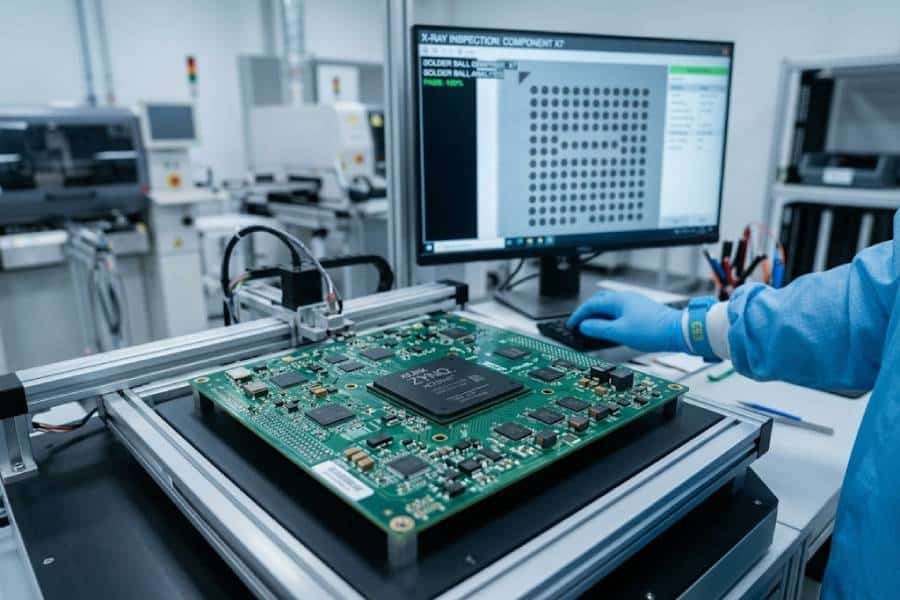
- X-ray inspection for BGA and hidden joints
- Full DFM analysis focused on material compatibility
- Rapid prototyping to production capability
Proper material selection combined with experienced SMT process control is the key to high yield and long-term product reliability.
Choosing the Right PCB Substrate for Success
There is no universally best PCB substrate material — only the most suitable one for your specific application, budget, performance requirements, and manufacturing process.
- FR4 remains the reliable workhorse for the majority of standard applications.
- Rogers and high-performance laminates excel in high-frequency and RF designs.
- Aluminum MCPCB is the go-to solution for superior thermal management.
- Polyimide enables flexible and space-constrained innovations.
- Hybrid stack-ups often provide the smartest balance between performance and cost.
The key to project success lies in understanding the trade-offs in electrical performance, thermal behavior, mechanical properties, and SMT assembly compatibility — then making an informed decision early in the design phase.
Making the right material choice from the beginning helps you achieve better signal integrity, higher reliability, lower defect rates, and optimized overall cost. Choosing incorrectly can lead to costly redesigns, production delays, and field failures.
At JHYPCB, we have years of experience manufacturing and assembling PCBs with all major substrate materials — from standard FR4 to complex Rogers + FR4 hybrid boards, Aluminum MCPCBs, and Rigid-Flex designs. Our team understands not just material properties, but how each material behaves throughout the entire SMT assembly process.
Ready to move forward with your project?
We offer:
- Free material selection consultation
- Professional DFM (Design for Manufacturability) analysis focused on substrate choice
- Fast quoting with multiple material options
- High-quality prototyping and volume production
- Full SMT assembly services with material-specific process optimization
📩 Contact JHYPCB today — upload your Gerber files and requirements, and our engineers will provide expert material recommendations and a competitive quote within 24 hours.
Whether your project is at the concept stage or ready for mass production, we are here to help you select the optimal PCB substrate and deliver high-quality boards on time.
Make the right material decision. Partner with JHYPCB for reliable results.