
Flex Circuits for Engineering Samples & Small Batches
Flexible PCB Prototype Fabrication
PCBELEC manufactures single-sided, double-sided and multilayer flex PCB prototypes for engineering evaluation and small-batch development. Bring your stackup, bend requirements, coverlay and stiffener details into one coordinated fabrication package.
Send your files and requirements to sales@pcbelec.com
Single-Sided, Double-Sided & Multilayer Flex
Flex-Specific Engineering Review
Prototype & Follow-On Small-Batch Builds
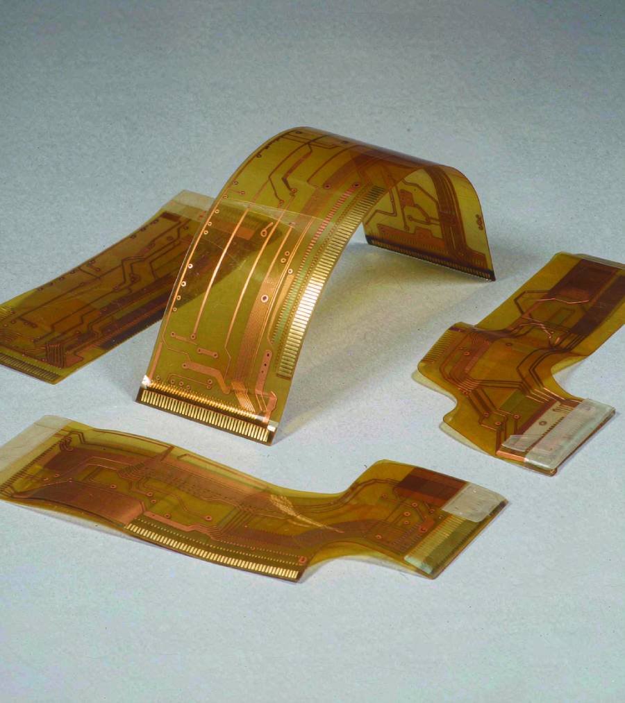
Choose the Construction for Your Build
Flex PCB Prototypes for Evaluation & Design Iteration
Get flexible bare boards for fit checks, electrical evaluation and the next design revision. We manufacture the selected construction against your approved files and requirements.
-
01
Single-Sided Flex Prototypes
One conductive layer for flexible interconnects and layouts suited to a single-layer circuit structure.
-
02
Double-Sided Flex Prototypes
Two conductive layers with plated interconnections where required, supported by defined pad, hole and coverlay details.
-
03
Multilayer Flex Prototypes
Additional conductive layers for more complex interconnects, with stackup, thickness and bend-area requirements reviewed together.
After evaluation, use the approved revision as the starting point for a revised prototype or follow-on small-batch quotation.
Identify local reinforcement in the flex drawing. If the design combines rigid board sections and flexible interconnects in one integrated build, use the dedicated rigid-flex prototype path.
Manufacturing Scope at a Glance
Flexible PCB Capabilities for Your Prototype Build
Match the prototype to the required construction. Our capability summary highlights the main flex manufacturing options; the full capability page provides detailed process ranges and conditions.
- Construction Range
- 1–10 Layers Single-sided, double-sided and selected multilayer flex constructions.
- PI Laminate Systems
- DuPont PI / Shengyi PI Define the required grade and material properties in the fabrication package.
- Flex-Specific Features
- Coverlay & Stiffeners Coordinate openings, reinforcement locations and bend-area requirements.
| Capability Item | Published Reference | Application to Your Build |
|---|---|---|
| Maximum Board Size | Single-sided: 480 × 4000 mm Double-sided: 480 × 1800 mm Multilayer: 236 × 600 mm | Confirm the applicable size with the selected stackup, copper, handling and delivery format. Manufacturing panel dimensions are listed separately. |
| Minimum Board Thickness | Single-sided: 0.05 mm ±0.02 mm Double-sided: 0.08 mm ±0.02 mm Multilayer: defined by the submitted construction | State the thickness target and identify coverlay, reinforcement and bend-area requirements. Local stiffeners must be defined separately. |
| Trace & Space | 1/2 oz copper, 1–6 layers: 0.076 / 0.076 mm 1 oz copper, 1–6 layers: 0.10 / 0.10 mm | Routing limits vary with copper and layer construction. Use the detailed capability table for other copper weights and finer-feature conditions. |
| Drilled Features | 1–6 layers, CNC: 0.20 mm 8 layers, CNC: 0.15 mm | These are drilled-hole references, not a universal finished-hole specification. Define PTH dimensions, pads and tolerances in the drawing. |
| Coverlay & Reinforcement | PI / PET protective film options; stiffener support within the published PI / FR4 substrate scope. | Specify coverlay openings, stiffener material, thickness, outline and location in the fabrication package. |
| Finish & Electrical Requirements | Surface-finish options, electrical verification and impedance-related requirements. | Define the selected finish, impedance targets and requested verification records for the order. |
Swipe horizontally to view the complete comparison.
These references describe separate manufacturing conditions, not a combination of limits guaranteed in one build. We confirm the applicable construction and specifications for the submitted prototype.
View Detailed Flex Capabilities →Define the Flexible Part of the Design
Bend Areas, Coverlay & Stiffener Details
Bring the mechanical and electrical requirements together before fabrication. We review the flex construction with the bend zones, protective openings and reinforced areas identified in your project package.
- Coverlay & Pad Openings
- Define the protective layer and the areas that must remain exposed for contact or downstream connection. Include: coverlay data, opening dimensions and any critical alignment requirements.
- Local Stiffeners
- Identify the reinforcement needed at connectors, handling areas or other supported zones. Keep local reinforcement details separate from the flexible stackup. Include: material, thickness, side, outline and location of each stiffener.
- Connection Areas & Thickness
- Define the pad arrangement, contact finish and finished thickness at the interface, including any local build-up. Include: interface dimensions, tolerances and a connector drawing where relevant.
Coordinate the Drawing
Show bend zones, coverlay openings, stiffener boundaries and thickness requirements together. Clearly distinguish the flat manufacturing outline from any installed-shape reference.
From Approved Construction to Finished Flex Boards
Engineering, Fabrication & Verification
We connect flex-specific engineering confirmation with manufacturing and inspection. The approved revision defines what is built and how the order is accepted.
-
01 / Engineering Confirmation
Resolve the Build Details
We review fabrication data, stackup, bend intent, coverlay and reinforcement details. Engineering questions and proposed adjustments are resolved before release.
-
02 / Prototype Fabrication
Manufacture the Approved Revision
We fabricate the flex boards using the accepted materials, construction, openings, finish and local reinforcement requirements.
-
03 / Inspection & Verification
Check the Agreed Requirements
We inspect the completed build and carry out the agreed electrical verification before preparing the boards for delivery.
Define Acceptance Before Release
Include critical features, applicable acceptance criteria and any requested records in the quotation package.
- Visual & Dimensional Outline, holes, contact areas, coverlay alignment and reinforcement details.
- Electrical Requirements Connectivity verification and any specified impedance targets or related records.
- Special Validation Requested bend, mechanical or environmental tests, with the scope and conditions agreed for the project.
Bare-board verification does not replace your product-level fit, function and use-condition validation. Identify special test requirements before the order is accepted.
PCB Testing & Inspection →Bring the Requirements into One Quote
Flex Prototype Pricing, Timing & Quotation Files
Send a consistent fabrication package with your quantity and required date. We use the defined construction and order scope to prepare pricing and confirm the manufacturing schedule.
Include in Your Request
- Fabrication Data & Revision Gerber files, matching drill data, outline, fabrication drawing, part number and revision.
- Stackup & Materials Layer construction, PI material requirements, copper, thickness targets and surface finish.
- Flex-Specific Drawings Bend zones, coverlay openings, stiffener details and critical connection-area dimensions.
- Acceptance Requirements Critical tolerances, electrical targets, requested tests and documentation.
- Quantity, Format & Destination Required quantity, individual circuits or panels, delivery destination and target date.
Keep all files on the same revision. Identify unresolved details and any changes to a previously quoted or approved package.
Manufacturing File Requirements →Before You Submit Your Flex Build
Flexible PCB Prototype FAQ
Answers about construction, bend requirements, engineering support, quotation files and follow-on orders.
What types of flex PCB prototypes do you manufacture?
We manufacture single-sided, double-sided and selected multilayer flex PCB prototypes. The published construction range covers 1–10 layers, with size, thickness and process conditions defined by the selected build. See the capability summary and detailed capability page for the applicable ranges.
What files are needed for a flex PCB prototype quote?
Send Gerber files, matching drill data and a fabrication drawing with the stackup, materials, copper and thickness requirements. Add coverlay and stiffener details, bend requirements, quantity, destination and required date. Use the quotation file checklist to prepare the package.
What bend information should I provide?
Mark the bend areas, direction, required radius and available space. State whether the circuit is formed during installation or moves repeatedly in use. Include any bend-life target with the intended validation conditions. Review the flex-specific drawing requirements before submission.
Can you fabricate flex prototypes with coverlay and stiffeners?
Yes. We support coverlay and local reinforcement within the published capability scope. Specify the coverlay openings and each stiffener's material, thickness, side, outline and location. Identify any critical connection-area thickness separately.
Is a flex PCB with a stiffener the same as rigid-flex?
No. Local reinforcement does not by itself make a flex circuit an integrated rigid-flex board. Designs combining rigid board sections and flexible interconnects in one integrated construction should use the rigid-flex prototype service for structure-specific preparation.
Do you provide engineering review before fabrication?
Yes. We review the manufacturing package and resolve engineering questions before release. The review covers the submitted construction, bend intent, coverlay, reinforcement and fabrication requirements. Circuit design and PCB layout remain with your design team.
How do you confirm pricing and turnaround?
We prepare the quotation and confirm the manufacturing schedule against the construction, materials, special processes, quantity and verification scope. Identify urgent deadlines and distinguish the required ship date from the required arrival date. Shipping and transit are planned separately from fabrication.
Can an approved prototype move into a repeat small-batch order?
Yes. Submit the approved revision, next quantity and any changes following evaluation. We reconfirm the construction, delivery format, acceptance requirements and schedule for the next build. See low-volume PCB fabrication for follow-on order planning.
Start Your Next Flex Prototype Build
Request Your Flexible PCB Prototype Quote
Send your fabrication files, stackup and flex-specific requirements with the quantity and target date. PCBELEC will review the build, resolve engineering questions and confirm pricing and fabrication timing.
Include bend zones, coverlay openings and stiffener details in the project package.
Request a Flex PCB Prototype Quote ↗
Or send your requirements directly to
sales@pcbelec.com
Defined Flex Construction
Approved Files & Revision
Confirmed Order Scope & Schedule
Related Technical Reading
Prepare Your Next Flex PCB Build
Continue with practical reading on flex stackups, bend requirements and local reinforcement before submitting your prototype.
Stackup Planning
Flexible PCB Stackup Optimization →
Read the stackup guide alongside your proposed layer construction and thickness requirements.
Bend Requirements
Static vs. Dynamic Bending in Flex PCBs →
Continue with the bending guide when defining installation shape or repeated movement requirements.
Local Reinforcement
Choosing a Flexible PCB Stiffener →
Read the selection guide when preparing reinforcement material, location and thickness details.