
Bare PCB Manufacturing for Vehicle Electronics
EV & New Energy Vehicle PCB Manufacturing
PCBELEC provides custom bare PCB manufacturing for electric vehicle battery management, onboard charging, power conversion and control applications. Define the board construction, materials and verification requirements for your prototype or production order.
Share your board requirements: sales@pcbelec.com
PCB Applications Across EV Systems
Start with the Vehicle System and Board Function
Electric vehicle PCB requirements vary across battery monitoring, charging, power conversion and vehicle control. Identify the function of each board before selecting its materials, copper specification and interconnect structure.
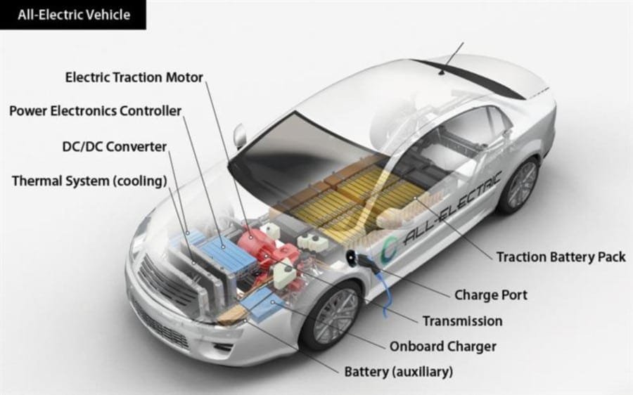
Board-Level Manufacturing Scope
This page covers bare printed circuit boards manufactured to the accepted design package. Control boards, driver boards and power-stage structures should be identified separately when defining the inquiry.
-
01
Battery Management Systems
Bare boards for cell-monitoring, balancing and battery-control electronics, with the connection layout and isolation requirements defined by the system design.
Manufacturing focus: stackup, connection features, material requirements and specified spacing.
-
02
Onboard Chargers
Board requirements for vehicle-mounted charging electronics, distinguishing control circuitry from power-circuit construction where applicable.
Manufacturing focus: finished copper, insulation features, thermal requirements and board geometry.
-
03
Inverters & Motor Control
Control and gate-driver board requirements for electric-drive systems. Identify the intended board structure rather than treating the complete power module as a conventional PCB.
Manufacturing focus: routing, isolation features, interfaces and copper requirements for the actual board.
-
04
DC/DC Converters
Bare-board requirements for power-conversion and associated control circuitry, based on the specified electrical and thermal operating conditions.
Manufacturing focus: conductor geometry, copper thickness, via structures and material selection.
-
05
Vehicle Control Units
Multilayer and other specified board constructions for vehicle-control electronics, including compact layouts and defined connector interfaces.
Manufacturing focus: layer construction, feature density, dimensional tolerances and verification.
Application names do not define a universal PCB specification. Final construction and acceptance requirements are agreed for the submitted design; system function and vehicle-level validation remain separate from bare-board verification.
Discuss Your EV PCB Requirements →Board Technology Selection
Match the PCB Structure to the Actual Design
EV electronics do not share one universal board construction. PCBELEC reviews the specified routing, copper, thermal and mechanical requirements before confirming the manufacturing scope.
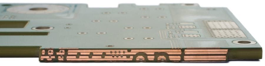
Specify the Board, Not Only the Application
A BMS controller, charger control board and power-circuit board may require different constructions. Include the actual stackup, copper specification and operating requirements with the design files.
-
01
Multilayer PCB
Evaluate multilayer construction where routing density, reference planes and defined power or signal distribution require an organized stackup.
Multilayer PCB Manufacturing → -
02
Heavy Copper PCB
Consider increased copper where the conductor design calls for it. Confirm finished copper, feature geometry and fabrication tolerances together rather than assigning current from copper weight.
Heavy Copper PCB Manufacturing → -
03
HDI PCB
Review HDI options when component escape routing and compact layouts require fine features and specified microvia or build-up structures.
HDI PCB Manufacturing → -
04
Flexible & Rigid-Flex PCB
Evaluate flexible interconnects where packaging and connection requirements justify them. Define bend conditions, stiffeners and rigid-to-flex transitions for the intended construction.
Flexible PCB →
Rigid-Flex PCB → -
05
Metal Core PCB
Consider metal-base construction only where it fits the electrical insulation, thermal path and mechanical design. It is not a universal replacement for multilayer control or power boards.
Metal Core PCB Manufacturing →
Board technology is selected for the design. An EV application label does not automatically require HDI, heavy copper, metal core or a particular layer count.
Review Manufacturing Capabilities →Electrical, Thermal & Mechanical Requirements
Define the Conditions Behind the Board Specification
Share the design requirements that govern the PCB, not only the vehicle application. PCBELEC reviews the manufacturing features against the submitted drawings, stackup and acceptance criteria.
Swipe horizontally if needed to view all engineering details.
| Requirement Area | Information to Provide | Manufacturing Review Focus |
|---|---|---|
| Materials & Dielectrics | Required laminate grade or approved alternatives, specified Tg, CTI, dielectric properties and applicable material requirements. | Material availability, stackup compatibility and whether substitutions require approval. |
| Copper & Conductors | Finished copper thickness, conductor geometry, plated-feature requirements and any specified minimum dimensions. | Etching and plating requirements, feature spacing and the tolerances applicable to the selected copper structure. |
| Insulation & Spacing | Required creepage and clearance, insulation boundaries, slots and cutouts. Identify the governing standard and design conditions. | Whether the specified geometry, routing tolerances and protective openings can be manufactured as defined. |
| Thermal Requirements | Operating temperature range, relevant thermal-cycle requirements, specified heat-transfer features and any material restrictions. | Construction, copper and via features against the approved design. Additional evaluation is separately scoped. |
| Stackup & Interconnects | Layer sequence, finished thickness, via definitions and any controlled impedance requirements or test structures. | Layer construction, interconnect process, specified tolerances and the applicable verification method. |
| Mechanical Interfaces | Board outline, mounting features, connector locations, datum references, flatness limits and mechanical environment requirements. | Profile and hole tolerances, alignment features and the agreed measurement conditions. |
| Finish & Identification | Surface finish, solder mask, marking content, traceability requirements, panel format and packaging instructions. | Process compatibility, identification method and the agreed delivery configuration. |
| Acceptance & Records | Required acceptance criteria, inspection or test methods, sampling, customer specifications and requested documentation. | The verification and reporting scope included in the quotation and released order. |
Copper Weight Is Not a Current Rating
Current capability must be evaluated with conductor geometry, layer arrangement, thermal conditions and allowable temperature rise. Do not assign a universal ampere rating from copper weight alone.
Voltage Alone Does Not Define Spacing
Insulation requirements depend on the applicable standard and conditions such as working and transient voltages, material group, pollution degree and altitude. Provide the design's specified distances and relevant conditions.
Bare-board manufacturing review does not replace circuit design, insulation coordination or vehicle-level safety and functional validation. Changes affecting the design require approval.
Quality, Traceability & Documentation
Define the Acceptance Basis for Your EV PCB
PCBELEC aligns the released design, manufacturing requirements and verification scope for the accepted order. Identify the customer criteria and documentation needed for your project before production release.
Keep the scope specific. State the required board acceptance class, applicable customer specifications and any additional qualification work. An application label alone does not define the delivery standard.
-
01
Approved Files & Material Requirements
Match the fabrication data, stackup, material specifications and engineering approvals to one released revision. Confirm any conditions for material substitutions before use.
-
02
Process & Dimensional Verification
Define the relevant construction checks, copper and plated-feature requirements, board geometry and specified tolerances. Additional measurement requirements belong in the accepted scope.
-
03
Electrical & Project-Specific Checks
Confirm the bare-board electrical verification requirements and any impedance or additional tests. Identify the method, coverage and acceptance limits where specified.
-
04
Identification & Delivery Records
Specify board and package identification, lot references, required reports and packaging instructions so the delivered order can be matched to its approved specification.
Specify the Records Your Project Needs
Confirm which records are included, their required format and any retention or traceability conditions. The list below is a project checklist, not a claim that every document is supplied with every order.
- Released revision and engineering approvals
- Material identification or requested evidence
- Microsection and plated-feature records
- Electrical and specified impedance results
- Dimensional or customer-specific inspection records
- Lot identification and agreed delivery documentation
Bare-board inspection does not replace module functional testing or vehicle-level qualification. Automotive approval and customer-specific documentation requirements need separate confirmation.
Explore Testing & Inspection →Prepare Your EV PCB Project
Send the Board Data with the Application Requirements
Identify the vehicle system and the function of the actual board. A clear fabrication package helps align the quotation, engineering review and order requirements.
Application & Project Stage
State whether the board is for BMS, onboard charging, inverter control, DC/DC conversion or vehicle control. Identify prototype, evaluation or production needs.
Fabrication Files & Revision
Include Gerber and drill data, fabrication drawings, stackup and the current revision. Mark preliminary files and identify the documents that govern the build.
Technical & Acceptance Requirements
Specify materials, finished copper, dimensions, critical spacing, tolerances, applicable customer criteria and the required verification records.
Quantity, Format & Schedule
Confirm quantity, individual boards or panels, packaging, destination and target date. Distinguish a required ship date from arrival at your facility.
If the package is not final, explain what remains open. Preliminary information may support an initial discussion, but final price, schedule and release conditions require confirmation.
Manufacturing File Guide →EV PCB Manufacturing FAQ
Clarify the Board Requirements Before You Order
Practical answers about board construction, manufacturing conditions and project preparation for electric vehicle electronics.
Need a project-specific answer?
sales@pcbelec.comWhich electric vehicle PCB projects can I discuss with PCBELEC?
Submit bare-board requirements for battery management, onboard charging, inverter and motor control, DC/DC conversion or vehicle-control electronics.
Identify the actual board function and construction. The vehicle-system name alone does not define the material, copper specification or manufacturing scope.
How should I specify materials for a BMS PCB?
Provide the required laminate grade or material criteria together with the stackup, insulation requirements, operating conditions and applicable customer specifications.
Identify whether alternatives are permitted. A BMS application label is not enough to select one universal material or layer construction.
Do all EV PCBs require heavy copper or HDI?
No. Heavy copper, HDI, multilayer, flexible and metal-core constructions address different design requirements. They are not mandatory features of every electric vehicle board.
Specify the conductor geometry, routing density, connection structure, thermal requirements and mechanical constraints that govern the actual design.
Can copper weight alone determine the current rating?
No. Current capability must be evaluated with conductor width and thickness, layer arrangement, thermal conditions and allowable temperature rise.
Include the finished copper and conductor requirements in the fabrication package. A general copper-weight description should not be treated as a universal ampere rating.
What high-voltage insulation information should I provide?
Provide the specified creepage and clearance distances, insulation boundaries, slots or cutouts, and the governing standard or customer requirement.
Include the relevant design conditions, such as working and transient voltages, material group, pollution degree and altitude. Bare-board manufacturing review does not replace system insulation coordination or safety validation.
What should be confirmed when moving from prototypes to production?
Confirm the released revision, materials, stackup, quantity, delivery format and acceptance requirements. Identify changes resulting from prototype evaluation.
Agree on the production schedule, identification, packaging and requested records. Do not assume an earlier prototype order automatically defines the next production build.
How are automotive quality and documentation requirements agreed?
Identify the required board acceptance criteria, customer specifications, traceability, inspection methods and delivery records before quotation.
Any required supplier certifications, approval submissions or additional qualification work need explicit confirmation. Bare-board verification is separate from module functional testing and vehicle-level approval.