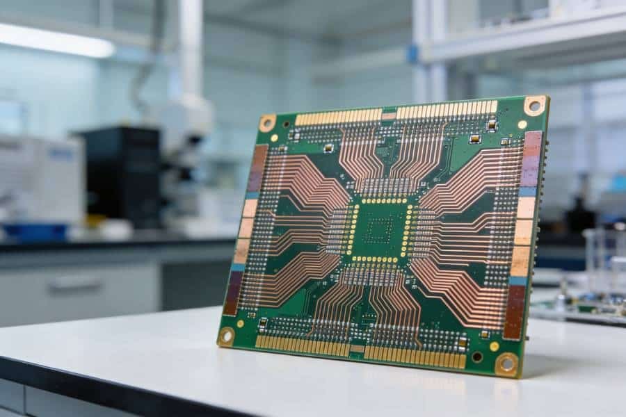
Flexible Circuit Material Selection Guide
Polyimide PCB Material for Flexible, Rigid-Flex and High-Temperature Circuits
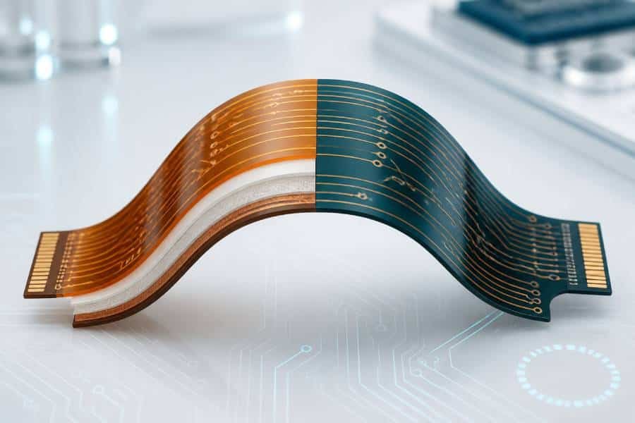
Polyimide PCB material provides the thermal stability, mechanical flexibility and dimensional reliability required for demanding flexible and rigid-flex circuit designs. Unlike glass-reinforced FR-4 laminates, polyimide film can bend, fold and conform to compact assemblies while maintaining electrical insulation and circuit integrity.
This guide explains how polyimide material systems work, how they compare with FR-4 and High Tg materials, and what engineers should define before selecting a manufacturable flex or rigid-flex stackup.
- Flexible dielectric for static and dynamic bend applications
- High-temperature stability for demanding operating and assembly conditions
- Material systems for flexible, rigid-flex and compact electronic assemblies
What Is Polyimide PCB Material?
Polyimide PCB material is a high-performance polymer film and laminate system used primarily in flexible and rigid-flex printed circuits. It is selected when a circuit must combine electrical insulation with mechanical flexibility, dimensional stability and reliable performance during elevated-temperature operation or assembly.
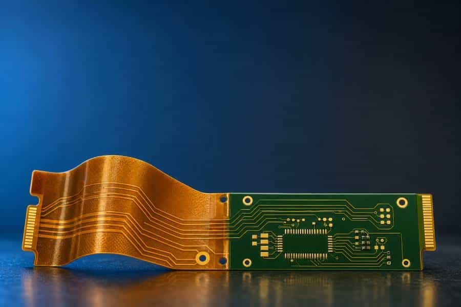
In a flexible circuit, polyimide commonly forms the base dielectric beneath the copper circuitry. In a rigid-flex design, polyimide-based flexible layers connect rigid board sections, allowing the circuit to fold, bend or route through compact mechanical spaces without relying on separate cables or multiple board-to-board connectors.
Unlike conventional FR-4, which uses woven glass reinforcement and is intended for rigid boards, polyimide is typically supplied as a thin film. This film-based construction enables controlled flexing when copper type, layer arrangement, coverlay, bend radius and strain-relief features are designed as one complete system.
Polyimide Is a Material System, Not Only a Base Film
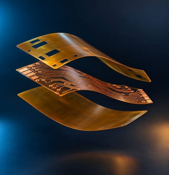
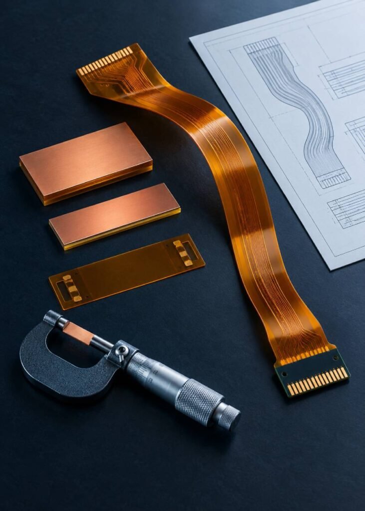
A manufacturable polyimide circuit is defined by more than the PI base film. Depending on the design, the full material system can include copper foil, adhesive or adhesiveless bonding layers, coverlay, flexible solder mask, bonding film, stiffeners, shielding layers and rigid-section laminates.
Each element affects the finished circuit. Together, they influence total thickness, bend performance, dynamic-flex reliability, thermal behavior, impedance control, assembly compatibility and the available mechanical space inside the final product.
Why Polyimide Is Used in Flexible and Rigid-Flex Circuits
Polyimide is widely used in flexible and rigid-flex circuits because it supports a combination of properties that conventional rigid laminates cannot provide in the same way. Its value is not simply that it can bend. It enables controlled interconnection in applications where space, motion, heat exposure and long-term reliability must be managed together.
01
Flexible Mechanical Integration
Polyimide film allows circuits to bend, fold and conform to compact assemblies. This can reduce connector count, replace separate cable assemblies and support three-dimensional packaging where rigid boards cannot fit efficiently.
02
Thermal and Assembly Stability
Polyimide material systems are commonly selected for applications that must tolerate demanding thermal conditions during assembly and operation. The actual temperature capability depends on the complete stackup, including copper, adhesive, coverlay and any rigid-section materials.
03
Dimensional Reliability
Stable material behavior helps support fine circuit features, multilayer alignment and controlled mechanical interfaces. Dimensional performance should still be reviewed against the selected material family, processing method and final application environment.
04
High Reliability in Compact Designs
When designed around the correct bend geometry, copper type and reinforcement strategy, polyimide circuits can provide dependable interconnection in compact products exposed to repeated handling, vibration, thermal cycling or constrained installation space.
Flexibility Does Not Mean Unlimited Bending
Polyimide enables flexing, but the flex life of a finished circuit is determined by the entire construction. Copper foil type and thickness, total flex thickness, layer count, trace direction, bend radius, coverlay, neutral-axis placement and operating cycle count all influence reliability.
A static bend may only be formed during installation and then remain in place. A dynamic bend is repeatedly flexed throughout product use and requires a more conservative mechanical design. The flex region should be engineered for the actual duty cycle instead of being treated as a generic cable replacement.
Design the Bend Zone as a Dedicated Mechanical Area
Keep vias, plated holes, component pads, sharp trace-angle changes and abrupt stiffener transitions out of the primary bend region whenever possible. Use gradual trace routing, appropriate bend radius and a stackup designed for the intended static or dynamic movement.
How a Polyimide Flex Material System Is Built
A polyimide flex circuit is built from coordinated material layers rather than from a single flexible laminate. The material stackup should be selected according to circuit density, bend duty, thickness target, copper requirement, assembly process, shielding needs and mechanical interface conditions.
Swipe horizontally to view the complete flex material system.
| Material Element | Typical Role in the Construction | Why It Matters | Key Design Inputs |
|---|---|---|---|
| Polyimide Base Film | Primary flexible dielectric substrate beneath the circuit copper | Provides electrical insulation, flexible support and thermal stability for the flex construction | Film thickness, dimensional stability, bend duty, thermal exposure and overall thickness target |
| Copper Foil | Forms the conductive circuit pattern, pads, power paths and signal routing | Copper type, thickness and grain structure can affect flexibility, current capacity and fatigue performance | RA or ED copper selection, copper weight, trace geometry, current demand and bend-zone routing |
| Adhesive or Adhesiveless Core | Bonds copper to the polyimide base film, or uses a direct copper-to-PI construction | Influences total thickness, flexibility, thermal behavior, dimensional control and reliability | Application environment, layer count, density, bend life target, cost and thermal exposure |
| Coverlay or Flexible Solder Mask | Protects circuit traces while leaving selected pads and contact areas exposed | Helps protect copper during handling and flexing; material selection affects bend performance and pad definition | Opening geometry, trace coverage, bend-zone placement, assembly method and required protection level |
| Bonding Film | Joins flex layers or connects flexible layers to rigid sections in selected multilayer and rigid-flex constructions | Supports layer integration while affecting thickness, flow behavior, thermal response and registration | Layer count, stackup symmetry, press cycle, dielectric needs and rigid-flex transition design |
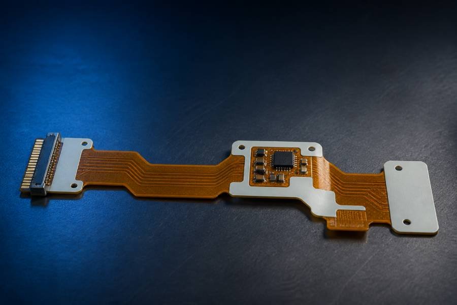
| Stiffener | Provides local reinforcement under connectors, component zones, ZIF contacts or handling areas | Improves local mechanical support without making the entire circuit rigid | Material type, thickness, placement, connector requirement, assembly load and clearance from bend zones |
Not every flexible circuit requires every material element. A simple single-layer static-flex design may use a much lighter construction than a multilayer dynamic-flex or rigid-flex assembly. The stackup should be reviewed according to the real mechanical and electrical conditions rather than copied from an unrelated flex design.
For projects that require flexible interconnects with rigid component areas, explore our Rigid-Flex PCB Manufacturing capabilities. For standard rigid designs that do not require bending, see our FR-4 PCB Material guide.
Polyimide vs FR-4 vs High Tg PCB Material
Swipe horizontally to compare material options.
| Selection Factor | Polyimide PCB Material | Standard FR-4 PCB Material | High Tg FR-4 PCB Material |
|---|---|---|---|
| Primary Material Form | Flexible polymer film or high-performance polyimide laminate system | Glass-reinforced epoxy laminate for rigid PCB constructions | Glass-reinforced epoxy laminate formulated for higher thermal stability |
| Mechanical Flexibility | Designed for controlled bending, folding and flex-to-install or repeated-motion applications | Rigid; not intended for flex zones or repeated bending | Rigid; improves thermal robustness but does not become a flexible circuit material |
| Thermal and Assembly Stability | Commonly selected for demanding thermal exposure; actual performance depends on the PI film, copper, adhesive and coverlay system | Suitable for many standard electronics applications within the selected laminate’s limits | Provides a more thermally robust rigid-board path for lead-free assembly, thermal cycling and higher-temperature operation |
| Rigid-Flex Compatibility | Core flexible dielectric material for flex layers and rigid-flex interconnect regions | Commonly used in rigid sections, but not typically used as the repeatedly flexed dielectric | Often evaluated for rigid sections where improved thermal stability is required alongside polyimide flex layers |
| Moisture Considerations | Moisture absorption and moisture-management requirements should be reviewed for the selected PI system and operating environment | Generally offers more familiar moisture behavior for conventional rigid PCB processing | Depends on the selected resin system; evaluate against thermal and humidity reliability requirements |
| Relative Material and Processing Cost | Higher due to specialized materials, flex processing and stackup complexity | Generally the most economical option for standard rigid constructions | Usually higher than standard FR-4, but often lower than a complete polyimide flex or rigid-flex construction |
| Best-Fit Design Direction | Flexible, rigid-flex, compact and high-reliability designs where bending or PI-level thermal stability is essential | Cost-efficient rigid boards with standard thermal and mechanical requirements | Rigid boards requiring stronger thermal stability without the need for flexing |
Choose polyimide when the circuit must bend, integrate rigid and flexible sections, or operate under conditions where a conventional rigid laminate is not suitable. Choose standard FR-4 when the circuit remains rigid and cost efficiency is the dominant requirement. Choose High Tg FR-4 when the design remains rigid but needs stronger thermal stability during assembly, thermal cycling or elevated-temperature operation.
For conventional rigid-board constructions, see our FR-4 PCB Material guide. For rigid applications that need a more thermally stable epoxy laminate, explore our High Tg PCB Material guide.
Key Polyimide Material Properties to Evaluate
Polyimide should be evaluated as a material system rather than by one headline property. A stackup that performs well in a static installation may not be suitable for repeated flexing, high humidity, fine-pitch routing, controlled impedance or a demanding reflow and thermal-cycling profile.
01
Flexibility and Bend Reliability
The required bend duty is one of the most important inputs. A static-flex section may bend once or only occasionally during installation. A dynamic-flex section moves repeatedly during product use and typically requires more conservative material, copper, routing and bend-radius decisions.
Evaluate total flex thickness, copper type, copper thickness, layer count, trace routing direction, coverlay construction, bend radius, neutral-axis balance and the expected number of flex cycles. The flex zone should be treated as a mechanical design feature, not simply as a smaller version of a rigid PCB.
02
Thermal Stability and Assembly Exposure
Polyimide materials are frequently selected because they maintain useful mechanical and electrical performance during demanding thermal exposure. However, a finished flexible circuit also includes copper, coverlay, adhesive or bonding layers, rigid-section materials and assembly interfaces. The stackup must be checked against its actual reflow profile, operating temperature range and thermal-cycling conditions.
03
Dimensional Stability and Fine Features
Polyimide should be evaluated as a material system rather than by one headline property. A stackup that performs well in a static installation may not be suitable for repeated flexing, high humidity, fine-pitch routing, controlled impedance or a demanding reflow and thermal-cycling profile.
04
Moisture and Environmental Exposure
Some polyimide systems absorb more moisture than conventional rigid laminates. Moisture can affect dimensional behavior and electrical performance, particularly when humidity, high-frequency behavior, long-term reliability or high-temperature assembly are important. Storage, handling, pre-bake requirements and the final operating environment should therefore be considered during material selection.
05
Electrical Performance and Impedance
For high-speed or RF-related flex interconnects, evaluate dielectric behavior, conductor geometry, adhesive layers, moisture exposure and stackup consistency together. Polyimide may be suitable for many flexible interconnect applications, but the required impedance, frequency range and loss target should determine whether PI, LCP or another specialized flexible material system is the better choice.
Polyimide Film Thickness and Total Flex Thickness
Polyimide base-film thickness is an important stackup input because it influences flexibility, mechanical support, dielectric spacing, total circuit thickness and the bend radius that the finished flex region can reasonably accommodate. Common polyimide film options for flexible circuits include thin constructions around 12.5 μm or 25 μm, medium constructions around 50 μm, and thicker film options such as 75 μm or 125 μm. The available range depends on the selected material family and construction method.
Thinner polyimide films can help reduce total flex thickness and support tighter, more flexible circuit constructions. Thicker polyimide films can provide more mechanical support and dielectric spacing, but they also increase the stiffness of the flex region. The appropriate base-film thickness should therefore be selected according to the actual bend duty, copper weight, layer count, voltage-isolation requirement, handling condition and available mechanical space.
Base-film thickness alone does not define the finished circuit thickness. Copper foil, adhesive or adhesiveless construction, coverlay, bonding films, plating, surface finish and any local stiffener all contribute to the final stackup. For bend reliability, calculate and review the total thickness of the actual moving flex zone rather than only the nominal PI film thickness.
Swipe horizontally to compare polyimide film thickness options.
| Nominal PI Film Thickness | Typical Selection Direction | Potential Benefits | Key Tradeoffs to Review |
|---|---|---|---|
| 12.5 μm (0.5 mil) | Ultra-thin, compact or highly flexible circuit regions | Helps reduce total flex thickness and can support tighter mechanical packaging | Lower mechanical support, tighter handling requirements, stackup sensitivity and limited dielectric spacing |
| 25 μm (1 mil) | Common thin-flex and dynamic-flex material direction | Balances low profile, flexibility and practical dielectric support for many flex designs | Must still be evaluated with copper thickness, coverlay, bend radius, voltage requirement and expected flex cycles |
| 50 μm (2 mil) | General-purpose flex and selected rigid-flex constructions | Provides additional mechanical support and dielectric spacing while maintaining flexible-circuit capability | Increases total thickness and flex stiffness compared with thinner PI film options |
| 75–125 μm (3–5 mil) | Applications requiring greater support, dielectric spacing or a more robust material base | Can improve handling robustness and support higher-thickness or more mechanically stable constructions | Reduces flexibility, increases minimum practical bend radius and may not be suitable for active dynamic-bend zones |
These thicknesses are material-selection references, not fixed manufacturing limits or universal stackup recommendations. The final polyimide thickness should be confirmed through stackup review based on copper weight, adhesive system, coverlay, bend requirement, electrical isolation, mechanical clearance, assembly process and reliability target.
How to Read a Polyimide PCB Material Datasheet
A polyimide datasheet should be used to compare a specific material family under clearly defined test conditions—not as a universal prediction of finished PCB performance. The values that matter most depend on whether the circuit will bend, operate at elevated temperature, carry high-speed signals, experience humidity exposure or support a high-reliability application.
For flexible and rigid-flex circuits, review the base-film data together with the copper construction, adhesive or adhesiveless core, coverlay, bonding materials and intended assembly process. A strong base-film property does not automatically guarantee the same performance after the complete stackup has been laminated, patterned, assembled and installed.
Swipe horizontally to review key polyimide material parameters.
| Datasheet Parameter | What It Indicates | Why It Matters for PCB Design | What to Confirm Before Release |
|---|---|---|---|
| Film Thickness and Tolerance | Nominal PI thickness and allowed variation for the base film or coverlay | Affects total flex thickness, bend behavior, dielectric spacing, impedance and mechanical clearance | Confirm the complete flex-zone thickness after copper, adhesive, coverlay, plating and finish are included |
| Thermal Properties | Relevant thermal-transition, decomposition, thermal-aging or short-term solder-exposure data | Helps assess compatibility with reflow, operating temperature, thermal cycling and material aging conditions | Review the actual assembly profile and long-term operating environment for the entire stackup |
| CTE and Dimensional Stability | Material expansion behavior and dimensional change under specified conditions | Influences multilayer registration, rigid-flex transitions, fine features, connector alignment and thermal reliability | Confirm test direction, temperature range, humidity condition and compatibility with copper and rigid-section materials |
| Dielectric Constant and Loss | Electrical behavior measured at a stated frequency, method and environmental condition | Important for controlled impedance, high-speed interconnects, RF flex regions and signal-loss evaluation | Request values at the intended frequency and condition, including any adhesive layer present in the signal path |
| Moisture Absorption | The material’s tendency to absorb moisture under the stated test method | Can affect dimensional stability, electrical behavior, reflow preparation and performance in humid operating environments | Define storage, dry-pack, pre-bake and environmental reliability requirements for the intended application |
| Mechanical and Peel Properties | Tensile behavior, elongation, copper adhesion or peel-strength data under defined conditions | Supports material selection for handling, lamination, termination regions and bend reliability evaluation | Do not use peel strength alone as a dynamic-flex-life predictor; review the entire bend-zone construction |
| Flammability and Compliance Documentation | Material-specific certification, declaration and traceability documentation | May be required for regulated industries, customer specifications or end-product compliance | Confirm the exact material grade, applicable file or declaration, revision level and project-specific requirement |
Engineering Input Checklist
Before You Finalize a Polyimide Flex Stackup
Define the complete mechanical, thermal and electrical environment before selecting the material system. The right stackup depends on how the circuit will move, assemble and operate—not on the PI film alone.
Is the flex section static, flex-to-install or repeatedly dynamic?
What bend radius, bend direction and expected flex-cycle exposure apply?
What total thickness, copper weight and layer count can the mechanical space accept?
Are RA copper, adhesiveless construction or balanced layer placement needed?
What reflow profile, operating temperature and thermal-cycling conditions will the circuit experience?
Do humidity, impedance control, shielding or connector-stiffening requirements affect the stackup?
Material-level properties are only one input. Final reliability depends on the complete flex construction, mechanical design and operating environment.
Adhesive-Based vs Adhesiveless Polyimide Materials
One of the most important flex-material decisions is whether the copper is bonded to the polyimide film through a dedicated adhesive layer or through an adhesiveless construction. Both material paths are widely used. The correct choice depends on thickness target, circuit density, bend duty, thermal exposure, impedance needs, reliability expectations and project cost.
Adhesive-Based Polyimide Construction
In an adhesive-based flex core, a flexible adhesive layer bonds the copper foil to the polyimide base film. This approach is well established and can provide a practical material path for many flex-only and rigid-flex applications. The adhesive layer must be considered as part of the dielectric structure because it adds thickness and influences thermal, dimensional and electrical behavior.
Adhesiveless Polyimide Construction
In an adhesiveless construction, the copper is bonded directly to the polyimide film without a separate adhesive layer between them. This can support thinner constructions, tighter dimensional control and improved suitability for selected high-density, dynamic-flex or thermally demanding applications. It should be specified where the expected performance benefit justifies the material and processing requirements.
Swipe horizontally to compare flex core constructions.
| Selection Factor | Adhesive-Based Polyimide Core | Adhesiveless Polyimide Core |
|---|---|---|
| Basic Construction | Copper foil is bonded to polyimide film through a dedicated flexible adhesive layer | Copper is bonded directly to polyimide film without a separate adhesive layer between the copper and PI |
| Stackup Thickness | Includes adhesive thickness as part of the material construction | Can support thinner constructions when reduced thickness is an important requirement |
| Flex and Dynamic-Bend Considerations | Suitable for many flex applications when the stackup and bend zone are designed correctly | Often evaluated for demanding dynamic-flex, high-density or thin-flex designs where construction control is especially important |
| Thermal and Dimensional Considerations | The adhesive layer should be evaluated for thermal exposure, flow behavior, dimensional control and assembly conditions | Removing the adhesive layer can support improved dimensional consistency and thermal response in selected designs |
| Electrical and Impedance Considerations | Adhesive becomes part of the dielectric structure and should be included in impedance and high-frequency evaluation | May simplify selected thin or controlled-impedance constructions, but the full stackup still requires electrical validation |
| Relative Cost and Availability | Often a practical, established and cost-conscious material path for many standard flex constructions | May involve a higher material cost or more specialized process path depending on the selected construction |
| Best-Fit Direction | Standard flex or rigid-flex applications where established construction, suitable peel strength and balanced cost are priorities | Thin, high-density, thermally demanding or reliability-critical flex applications where the performance benefit supports the added complexity |
Do not choose adhesiveless material solely because it is more advanced, and do not choose adhesive-based material solely because it is familiar. Define the mechanical duty, thickness limit, conductor geometry, thermal exposure, impedance target, production volume and reliability requirement first. The appropriate polyimide construction follows from those inputs.
Coverlay, Stiffeners and Bonding Films in Polyimide Circuits
A flexible circuit needs more than a polyimide base film and etched copper. Coverlay, stiffeners and bonding films help protect the circuit, create controlled local rigidity and integrate layers into a manufacturable flex or rigid-flex construction. Each material should be selected according to the actual mechanical, assembly and environmental demands of the application.
Coverlay: Flexible Protection for Copper Circuits
Coverlay is typically a polyimide film with an adhesive layer used to protect and electrically insulate flexible copper circuitry. It is commonly used instead of rigid-board solder mask in flex regions because it can move with the circuit while protecting traces from handling damage, contamination and mechanical stress.
Coverlay openings expose pads, contact fingers and selected connection areas. Their geometry must account for registration tolerance, adhesive flow, pad spacing and the intended assembly method. In an active bend zone, continuous, well-bonded coverlay coverage helps protect copper, while unnecessary opening patterns or abrupt material changes can create localized stress concentrations.
Stiffeners: Local Support Without Losing Overall Flexibility
A stiffener is a localized reinforcement layer added where a flex circuit needs extra support. Typical locations include ZIF connector fingers, component-mounting zones, soldering areas, test interfaces and handling regions. The purpose is not to make the entire circuit rigid; it is to provide controlled support exactly where flatness, insertion force, solder-joint stability or local handling strength is required.
Common stiffener materials include polyimide, FR-4, stainless steel and aluminum. The appropriate material, thickness and profile depend on the required support, assembly temperature, connector specification, mass constraint and available installation space. Stiffener edges should not create a hard hinge directly at the bend line; a controlled transition area helps reduce concentrated bending stress.
Bonding Films: Building Multilayer Flex and Rigid-Flex Structures
Bonding film is a dielectric adhesive material used to join selected flexible layers or connect flex layers to rigid sections in multilayer flex and rigid-flex constructions. During lamination, its flow behavior and thickness affect layer adhesion, registration, final board thickness and the transition between flexible and rigid areas.
Bonding-film selection should be coordinated with copper distribution, drilled features, impedance requirements, thermal exposure and press-cycle conditions. In a bend zone, the stackup may need to limit or selectively open rigidizing materials so the flex region can move as intended.
Swipe horizontally to compare flex support materials.
| Material Element | Primary Function | Typical Application Areas | Key Design Considerations |
|---|---|---|---|
| Coverlay | Protects and electrically insulates flexible copper traces while maintaining circuit flexibility | Flex regions, trace protection areas, selected pad-opening patterns and moving circuit sections | Coverlay thickness, adhesive flow, opening geometry, registration, bend-zone coverage and assembly-pad clearance |
| Polyimide Stiffener | Adds local support with a material that remains compatible with flexible-circuit thermal conditions | Connector zones, soldering areas, local handling regions and moderate reinforcement requirements | Stiffener thickness, adhesive method, local planarity, thermal exposure and clearance from active bend zones |
| FR-4 Stiffener | Provides stronger local rigidity and a stable platform for connectors or component areas | ZIF connector fingers, component-mounting regions, insertion zones and test interfaces | Required support level, connector thickness requirement, edge-transition design, assembly process and added mass |
| Metal Stiffener | Delivers high local stiffness, dimensional support or specialized mechanical reinforcement | Applications requiring high insertion support, thin yet rigid reinforcement or defined mechanical interfaces | Material type, profile, adhesive, weight, electrical isolation, corrosion protection and mechanical integration |
| Bonding Film | Joins selected flex layers or supports flex-to-rigid layer integration during lamination | Multilayer flex, rigid-flex transitions, layer-bonding regions and selected dielectric interfaces | Flow behavior, thickness, registration, press cycle, copper distribution, dielectric requirement and bend-zone treatment |
Designing for Static Bend, Dynamic Bend and Rigid-Flex Reliability
Flexible circuit reliability depends on how the product will actually move. A circuit that bends once during installation has very different requirements from a circuit that flexes thousands or millions of times during normal use. Rigid-flex designs introduce an additional requirement: the transition between rigid and flexible regions must be engineered so that changes in thickness and stiffness do not create concentrated mechanical stress.
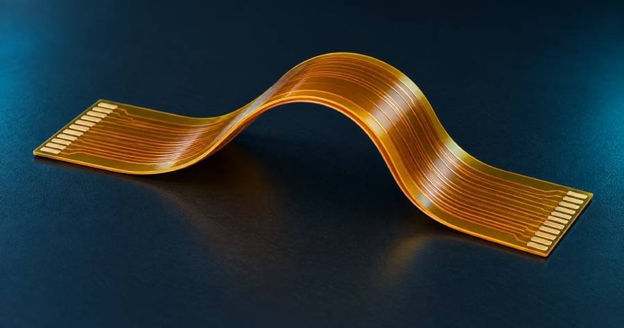
Static Flex: Bent Once or Positioned During Installation
Dynamic Flex: Repeated Movement Requires a More Conservative Design
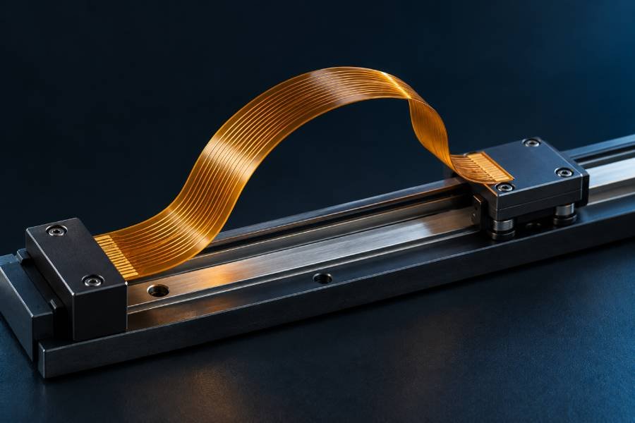
A dynamic-flex circuit is repeatedly bent during normal product operation. In this case, copper fatigue, coverlay adhesion, trace geometry, bend radius, neutral-axis placement and material construction become critical reliability factors. The flex area should be designed specifically for movement, rather than treated as a static circuit that happens to be bent more often.
Dynamic applications commonly benefit from thinner and more balanced flex constructions, larger bend radii, smooth trace routing, reduced copper thickness where electrically feasible, rolled-annealed copper and careful control of layer placement. Avoid vias, plated through-holes, components, abrupt corners, stiffener edges and sharp thickness changes within the active bend zone.
Rigid-Flex Transitions Need a Controlled Mechanical Interface
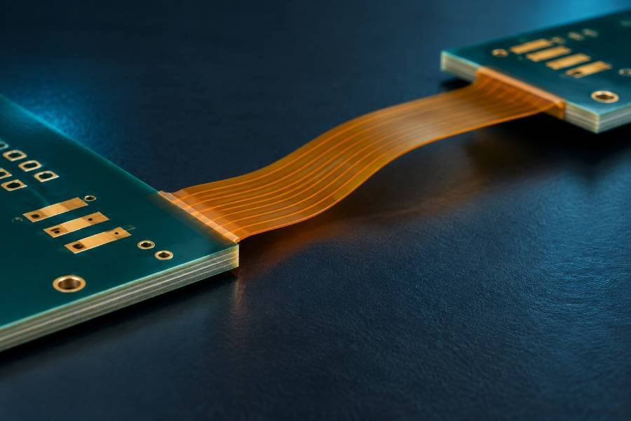
In a rigid-flex PCB, the flex layers pass between rigid sections and must accommodate changes in material thickness, copper distribution and local stiffness. The region near the rigid-to-flex transition should be reviewed for coverlay termination, bonding-material treatment, trace routing, stress relief and clearance from components or mounting features.
Do not place the primary bend line directly at the rigid edge or at the edge of a stiffener. Provide a defined flex transition area so bending forces are distributed through the intended flexible region rather than concentrated at a hard material boundary.
Swipe horizontally to compare flex reliability requirements.
| Design Factor | Static Flex Application | Dynamic Flex Application |
|---|---|---|
| Movement Pattern | Bent during installation, folding or occasional service, then remains largely fixed | Repeated bending during normal product operation throughout the intended service life |
| Primary Reliability Risk | Over-bending, installation damage, localized stress at a fixed bend or inadequate strain relief | Copper fatigue, coverlay or adhesive degradation, delamination and repeated stress concentration |
| Bend Radius Strategy | Defined from total flex thickness with appropriate design margin for the construction and installation process | Generally requires a significantly larger and more conservative bend radius to reduce cyclic strain |
| Copper and Stackup Direction | Construction can be selected for practical thickness, routing and installation needs | Often benefits from thinner, balanced constructions, ductile copper selection and careful neutral-axis control |
| Trace Routing in Bend Zone | Use smooth routing and avoid unnecessary stress features in the defined bend area | Use gradual, consistent trace routing; avoid abrupt changes, vias, plated holes, pads and tightly packed conductors in the active bend region |
| Stiffener and Component Placement | Keep stiffener edges and components away from the primary bend line where possible | Do not place stiffeners, components, vias or abrupt thickness transitions in the active bend zone |
| Validation Priority | Installation fit, bend geometry, assembly compatibility and final-position inspection | Cycle-life validation, mechanical fatigue testing, motion-path review and long-term reliability assessment |
Published bend-radius guidelines can be useful starting points, but they are not a substitute for application-specific stackup review and validation. Bend radius should be based on the total thickness of the actual flex region and the true movement profile. Dynamic applications usually require much more conservative design margins than static installations.
Match the Polyimide Material System to the Operating Environment
Polyimide selection should begin with the dominant operating condition. A stackup designed for occasional installation bending is different from one designed for continuous motion. A standard flexible interconnect is also different from a humidity-sensitive, high-frequency or regulated high-reliability application.
Dynamic-flex application
Prioritize bend-cycle target, bend radius, thin balanced construction, trace routing, copper selection and active-bend-zone validation.
High-temperature or harsh-environment application
Review the complete thermal profile, thermal cycling, chemical exposure, moisture conditions, coverlay, adhesive and assembly compatibility.
High-speed or RF flex interconnect
Evaluate Dk, Df, impedance, conductor roughness, adhesive presence, moisture behavior and the actual operating frequency.
Regulated or high-reliability project
Define material traceability, compliance documents, qualification requirements, acceptance criteria and any customer or industry-specific standards before stackup release.
Next Step: Stackup Review
Have Your Flex Requirements and Bend Conditions Defined?
Turn your bend duty, space constraints, copper requirements, stiffener needs and assembly conditions into a practical polyimide flex or rigid-flex stackup before prototype release.
Material, bend-zone and DFM guidance
How to Specify Polyimide PCB Material for Quotation
A complete flex-material specification gives the engineering and manufacturing team the information needed to evaluate stackup feasibility, bend reliability, material availability, tooling requirements and production cost. If the exact polyimide construction is not yet defined, provide the mechanical and electrical requirements that the finished circuit must meet.
Information to Include in Your Flex or Rigid-Flex RFQ
- Gerber files, drill files, board outline and mechanical drawing
- Prototype quantity, production quantity and expected annual volume
- Flex-only, rigid-flex or flex-to-install application type
- Layer count, target total thickness, polyimide base-film thickness, coverlay thickness and preferred stackup if known
- Polyimide base-film requirement, copper weight and copper foil preference if specified
- Static bend, dynamic bend or fold requirement, including bend direction and expected movement cycle
- Minimum bend radius, available bend space and mechanical installation condition
- Coverlay requirements, exposed-pad areas, contact fingers and surface-finish needs
- Stiffener material, thickness, location and connector or component support requirement
- Rigid-section material, layer count and thermal requirement for rigid-flex designs
- Impedance, shielding, controlled electrical performance or environmental exposure requirement
- Assembly method, component constraints, testing needs and delivery destination
- Required material family, customer-specified material grade or approved-vendor requirement, if applicable
- Required compliance documentation, material traceability, qualification records or restricted-substance declarations
- Application-specific reliability target, validation method and acceptance criteria, especially for dynamic-flex or regulated projects
Define Material Traceability and Qualification Requirements Early
For aerospace, automotive, medical, industrial or customer-controlled programs, material selection may require more than standard fabrication data. Identify any approved material list, customer-specified grade, compliance documentation, batch traceability, qualification record, environmental declaration or validation requirement before prototype release. Early confirmation helps prevent a stackup that is technically functional but not acceptable for the final program.
Describe the Mechanical Use Case, Not Only the PCB Geometry
For flex and rigid-flex projects, board dimensions and layer count are not enough. Explain how the circuit will bend, where it will be supported, whether it will move repeatedly, which areas must remain flat and how it connects to the final assembly. A short mechanical-use description can prevent an otherwise correct electrical layout from being built with an unsuitable material construction.
Provide the Flex Zone as a Defined Design Area
Identify the active bend zone, bend direction, bend radius, rigid-to-flex transition area, stiffener locations and any components or connectors near the moving region. This enables an earlier DFM review of trace routing, coverlay openings, copper distribution and mechanical clearances before manufacturing begins.
Ready for Fabrication?
Have Your Polyimide Flex or Rigid-Flex Requirements Ready for Quotation?
When your design files, stackup inputs, bend requirements and mechanical details are defined, our manufacturing team can review the proposed construction and support your flexible or rigid-flex PCB project from prototype through production.
Prototype, production and assembly support
hen Polyimide PCB Material Is Not the Right Choice
Polyimide is a highly capable material system, but it should not be specified by default for every PCB project. Its additional cost, specialized processing and material-selection requirements are justified when a design needs flexibility, rigid-flex integration, elevated-temperature stability or demanding mechanical reliability. If those requirements are not present, another material path may provide a more practical solution.
Choose FR-4 When the Circuit Will Remain Rigid
If the circuit does not need to bend, fold or route through a three-dimensional mechanical space, standard FR-4 is often the most cost-effective and widely applicable choice. It supports complex multilayer routing, standard assembly processes and a broad range of general electronic applications without the additional material and manufacturing complexity of a flexible construction.
Choose High Tg FR-4 When Thermal Stability Is Needed Without Flexibility
If the main requirement is stronger thermal stability during lead-free assembly, elevated-temperature operation or thermal cycling, but the board remains rigid, High Tg FR-4 may be a more appropriate material path. It provides a thermally more robust rigid construction without requiring a polyimide flex stackup.
Evaluate PET or PEN for Cost-Sensitive, Low-Temperature Flex Applications
For simple flexible circuits with limited temperature exposure, low mechanical stress and cost-sensitive production targets, PET or PEN may be evaluated. These materials do not provide the same thermal margin and assembly compatibility as polyimide, so they should not be substituted into reflow-exposed, high-temperature or demanding dynamic-flex applications without a full engineering review.
Evaluate LCP for High-Frequency, Low-Moisture Flexible Interconnects
Polyimide is suitable for many flexible interconnect designs, but it may not be the optimal material when low dielectric loss, very low moisture absorption and stable high-frequency performance are the dominant requirements. In these cases, LCP or another specialized low-loss flexible material system may offer a more suitable electrical-performance path.
Improve the Mechanical Architecture When the Real Constraint Is Outside the PCB
Not every space or reliability issue should be solved by changing the PCB substrate. If the primary problem is connector placement, enclosure geometry, heat-sink integration, strain relief or cable routing, a mechanical redesign may provide a better outcome than specifying a more complex polyimide construction.
Material Selection Paths
Compare Other PCB Material Paths
Select the material system that addresses your primary design constraint—whether that is rigid-board cost, elevated-temperature stability, high-frequency performance or specialized flexible-circuit requirements.
FR-4 PCB Material
A practical and widely used material path for rigid multilayer, signal, control and general electronic designs that do not require a flex region.
Explore FR-4 Material →High Tg PCB Material
A more thermally stable rigid-laminate direction for applications that remain rigid but need stronger performance during thermal exposure and lead-free assembly.
Explore High Tg Material →RF / High Frequency Materials
A specialized material path for controlled dielectric behavior, low-loss transmission and frequency-sensitive circuit performance.
Explore RF Materials →Specialty Laminates
A custom-material direction for designs that require specified resin systems, unusual dielectric targets, advanced environmental resistance or customer-defined laminate requirements.
Explore Specialty Materials →Frequently Asked Questions About Polyimide PCB Material
Polyimide PCB material is a high-performance polymer film and laminate system used primarily in flexible and rigid-flex circuits. It provides electrical insulation, thermal stability and mechanical flexibility, allowing circuits to bend, fold or integrate into compact three-dimensional assemblies.
Polyimide is the generic material category. Kapton is a well-known brand family of polyimide films. A PCB specification should define the required material performance, thickness, copper construction and stackup rather than relying only on a brand name.
Polyimide is commonly used as a flexible dielectric for flex and rigid-flex circuits, while FR-4 is a glass-reinforced epoxy laminate used primarily for rigid boards. Polyimide is selected when bending, folding, compact mechanical integration or higher thermal stability is required. FR-4 is generally more economical for circuits that remain rigid.
Polyimide enables flexible circuits, but repeated-bend reliability depends on the complete construction. Copper type and thickness, total flex thickness, bend radius, trace routing, coverlay, neutral-axis design, stiffener placement and expected movement cycles all affect flex life. Dynamic-flex applications require a dedicated mechanical design and validation process.
Adhesive-based material uses a flexible adhesive layer between copper foil and polyimide film. Adhesiveless material bonds copper directly to the polyimide without that separate layer. Adhesiveless constructions can support thinner or more demanding designs, while adhesive-based constructions remain a practical and established choice for many flex applications. The correct option depends on thickness, bend duty, thermal exposure, electrical needs and cost.
Stiffeners provide local reinforcement where a flexible circuit needs support, flatness or controlled thickness. They are commonly used under connectors, component areas, ZIF fingers, soldering zones and test interfaces. A stiffener is designed to reinforce a specific location without removing flexibility from the entire circuit.
Provide Gerber files, mechanical drawings, quantity, layer count, target thickness, copper requirements, flex or rigid-flex construction, bend conditions, coverlay details, stiffener information, surface finish, assembly requirements and the final application environment. For dynamic-flex designs, include the expected movement profile and bend-cycle requirements.
Engineering Review & Manufacturing Support
Turn Your Flex Requirements Into a Manufacturable Polyimide PCB
Share your bend requirements, stackup targets, copper construction, stiffener needs, mechanical constraints and design files. Our engineering team can help evaluate a polyimide flex or rigid-flex material system that aligns reliability, manufacturability, assembly conditions and production requirements.
- Polyimide material and stackup review
- Bend-zone, coverlay and stiffener evaluation
- Prototype, production and assembly support
From flex material review to prototype, rigid-flex fabrication, assembly and production support.