PCB MATERIALS / RIGID PCB SUBSTRATES
FR-4 Material for PCB Fabrication
Properties, Types, and Practical Selection Guidance
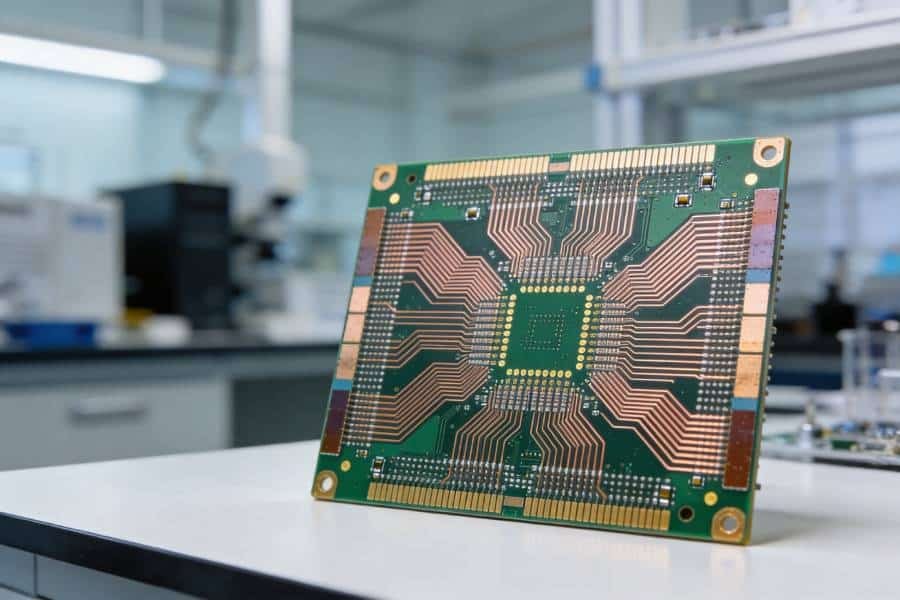
FR-4 is the most widely used substrate material for rigid printed circuit boards. Made from epoxy resin and woven glass reinforcement, it delivers a practical balance of electrical insulation, mechanical strength, thermal stability, manufacturability, and cost.
PCBELEC supports standard, mid-Tg, high-Tg, halogen-free, and application-specific FR-4 material options for prototypes, quick-turn orders, and volume PCB production. Our engineering team can help match the laminate system and PCB stackup to your thermal, electrical, mechanical, and assembly requirements.
- Standard, Mid-Tg & High-Tg Options
- Rigid and Multilayer PCB Support
- Controlled Impedance Stackups
- Prototype to Volume Production
THE FOUNDATION OF RIGID PCBS
What Is FR-4 Material?
FR-4 is a flame-retardant, glass-reinforced epoxy laminate used as the insulating base material in rigid printed circuit boards. In a typical PCB construction, copper foil is bonded to one or both sides of an FR-4 laminate and then patterned to form conductive traces, pads, and planes.
The term “FR-4” refers to a flame-retardant grade of epoxy-glass laminate commonly used for rigid and multilayer PCBs. It is valued for its balance of electrical insulation, mechanical strength, dimensional stability, thermal performance, manufacturability, and cost.
FR-4 is not one universal material formulation. Its actual performance varies by laminate manufacturer, resin system, glass style, resin content, copper foil treatment, and construction. For critical designs, confirm the approved material data sheet and final PCB stackup before fabrication.
FR-4 AT A GLANCE
A versatile epoxy-glass substrate for rigid PCBs
- Base structure: Epoxy resin reinforced with woven glass fabric
- Typical use: Rigid and multilayer PCB fabrication
- Main strengths: Insulation, strength, thermal stability, and cost efficiency
- Material grades: Standard Tg, mid-Tg, high-Tg, halogen-free, and low-loss options
- Copper construction: Copper-clad laminate, cores, and prepregs
- Selection basis: Thermal, electrical, mechanical, assembly, and compliance requirements
For design-critical applications, material values must be confirmed against the selected laminate data sheet and final stackup.
UNDERSTANDING PCB STACKUP
How FR-4 PCB Material Is Constructed
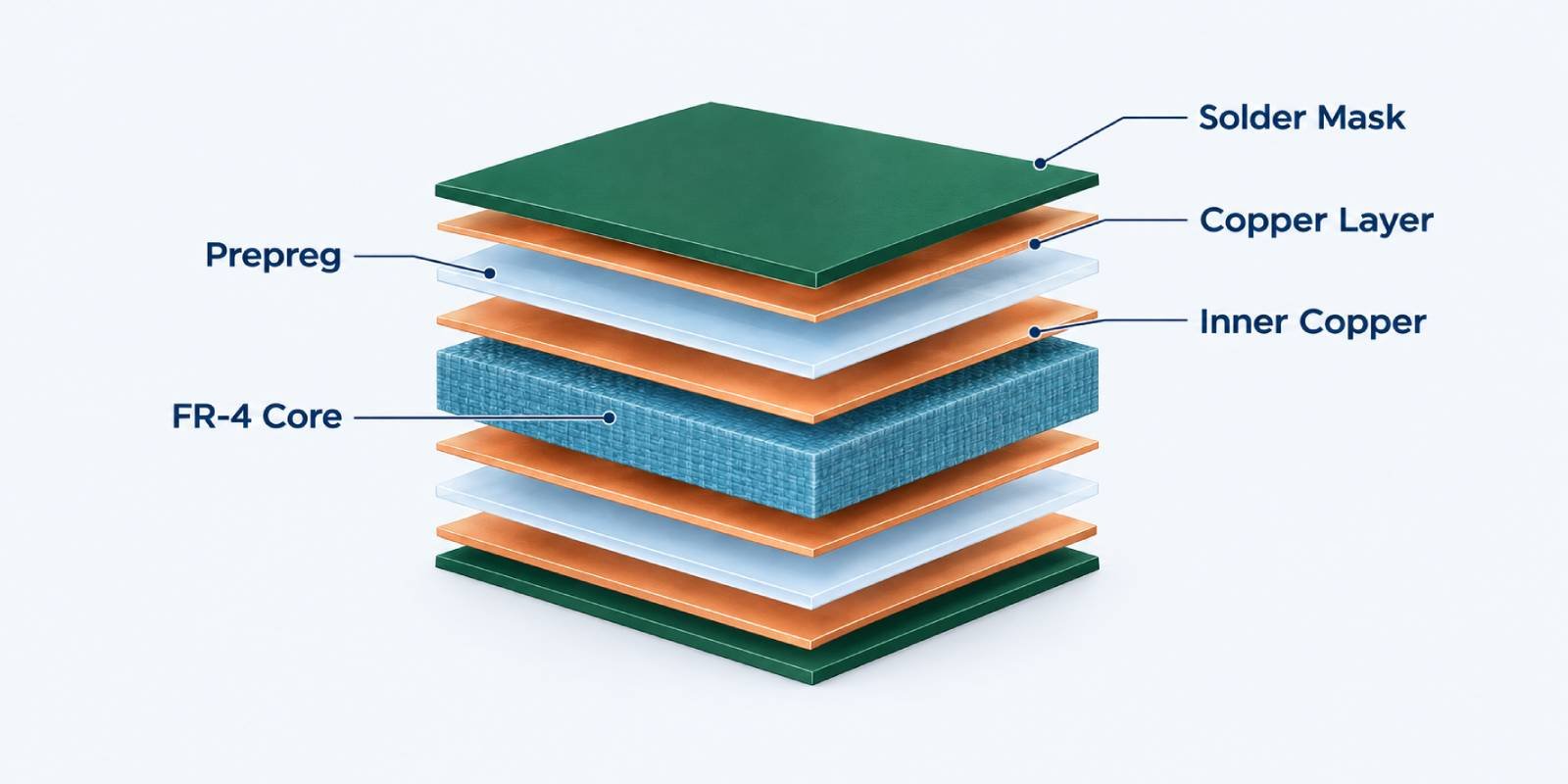
An FR-4 PCB is not made from one uniform sheet of material. It is built from copper-clad laminates, cured FR-4 cores, and prepregs that are bonded together during lamination to create the required layer count, finished thickness, dielectric spacing, and electrical performance.
In a simple two-layer PCB, copper foil is bonded to both sides of an FR-4 laminate. In a multilayer PCB, multiple inner-layer cores and prepregs are combined with outer copper foils under heat and pressure to form one rigid board structure.
The selected core thickness, prepreg construction, resin content, copper weight, and layer arrangement all influence the final PCB thickness, impedance behavior, thermal performance, resin flow, and long-term reliability.
Copper Foil
Copper foil forms the conductive layers of a PCB, including traces, pads, planes, and vias. Copper weight is selected based on current capacity, thermal needs, fabrication limits, and the required layer construction.
FR-4 Core
An FR-4 core is a fully cured epoxy-glass laminate with copper foil on one or both sides. It provides mechanical support and controlled dielectric spacing between copper layers.
Prepreg
Prepreg is partially cured epoxy-glass material that flows during lamination. It bonds PCB layers together and helps establish the final dielectric thickness between conductive layers.
Solder Mask and Surface Finish
Solder mask protects outer copper from oxidation and unintended solder bridging. Surface finishes such as ENIG, HASL, or OSP prepare exposed pads for reliable soldering, but they are separate from the FR-4 laminate system.
Why Stackup Matters
The same finished board thickness can be built with different FR-4 core and prepreg combinations. For controlled impedance, high-current, high-layer-count, or reliability-critical designs, the final stackup should be reviewed before fabrication rather than selected by thickness alone.
Related engineering resources: Multilayer PCB Manufacturing · Controlled Impedance PCB · Heavy Copper PCB
ENGINEERING PERFORMANCE FACTORS
Key FR-4 Material Properties
FR-4 performance is defined by more than its name or finished board thickness. The thermal, electrical, mechanical, and reliability characteristics of a laminate depend on its specific resin system, glass reinforcement, material construction, and test conditions.
The properties below help engineers evaluate whether a standard, mid-Tg, high-Tg, halogen-free, or low-loss FR-4 system is appropriate for the design. For production release, always verify critical values against the selected laminate data sheet and final PCB stackup.
01
Thermal Reliability
Tg, Td, and CTE affect material behavior during assembly and thermal cycling.
02
Signal Performance
Dk and Df influence impedance, propagation, and dielectric loss.
03
Electrical Safety
CTI supports insulation and creepage-distance evaluation.
04
Long-Term Durability
Moisture absorption, peel strength, and CAF resistance influence reliability.
Scroll horizontally to view all three columns.
| Property | What It Means | Why It Matters for PCB Design |
|---|---|---|
| Glass Transition Temperature (Tg) | The temperature range where the epoxy resin changes from a rigid, glass-like state toward a softer state. | A higher Tg generally provides more thermal margin during lead-free assembly, repeated reflow, and demanding operating conditions. |
| Decomposition Temperature (Td) | The temperature at which the laminate begins to degrade significantly. | Helps assess material tolerance during high-temperature assembly and thermal exposure. Td should be reviewed alongside Tg rather than used alone. |
| Coefficient of Thermal Expansion (CTE) | The rate at which the material expands as temperature changes, especially through the board thickness. | Z-axis expansion affects plated-through-hole, via, and multilayer reliability during thermal cycling. |
| Dielectric Constant (Dk) | A measure of how the dielectric material affects electromagnetic signal propagation. | Dk influences impedance and signal timing. It is especially relevant for controlled-impedance and higher-speed designs. |
| Dissipation Factor (Df) | A measure of dielectric energy loss as signals travel through the material. | Lower Df can reduce signal loss, making it more important for high-speed digital, RF, and high-frequency applications. |
| Comparative Tracking Index (CTI) | A measure of a material’s resistance to electrical tracking on its surface under voltage and contamination. | Higher CTI can support insulation coordination and creepage-distance considerations in higher-voltage designs. |
| Moisture Absorption | The tendency of the laminate to take up moisture from its environment. | Moisture can influence electrical properties, thermal behavior, and reliability during assembly or environmental exposure. |
| Peel Strength | The bond strength between copper foil and the laminate. | Adequate peel strength supports trace adhesion, rework durability, and fabrication reliability. |
| CAF Resistance | Resistance to conductive anodic filament growth through the laminate under moisture, bias, and thermal stress. | Important for fine-pitch, high-density, high-voltage, and long-life multilayer PCB applications. |
Note: Material-property data can vary by laminate series, glass style, resin content, copper treatment, test method, frequency, and environmental condition. Confirm all design-critical requirements with the approved material data sheet before fabrication.
Tg Alone Is Not a Complete Material Selection Rule
High Tg FR-4 can improve thermal processing margin, but Tg should not be used as the only selection criterion. For reliability-critical designs, also review Td, Z-axis CTE, CAF resistance, Dk/Df stability, moisture behavior, layer count, via structure, copper balance, assembly profile, and operating environment.
CHOOSE THE RIGHT LAMINATE SYSTEM
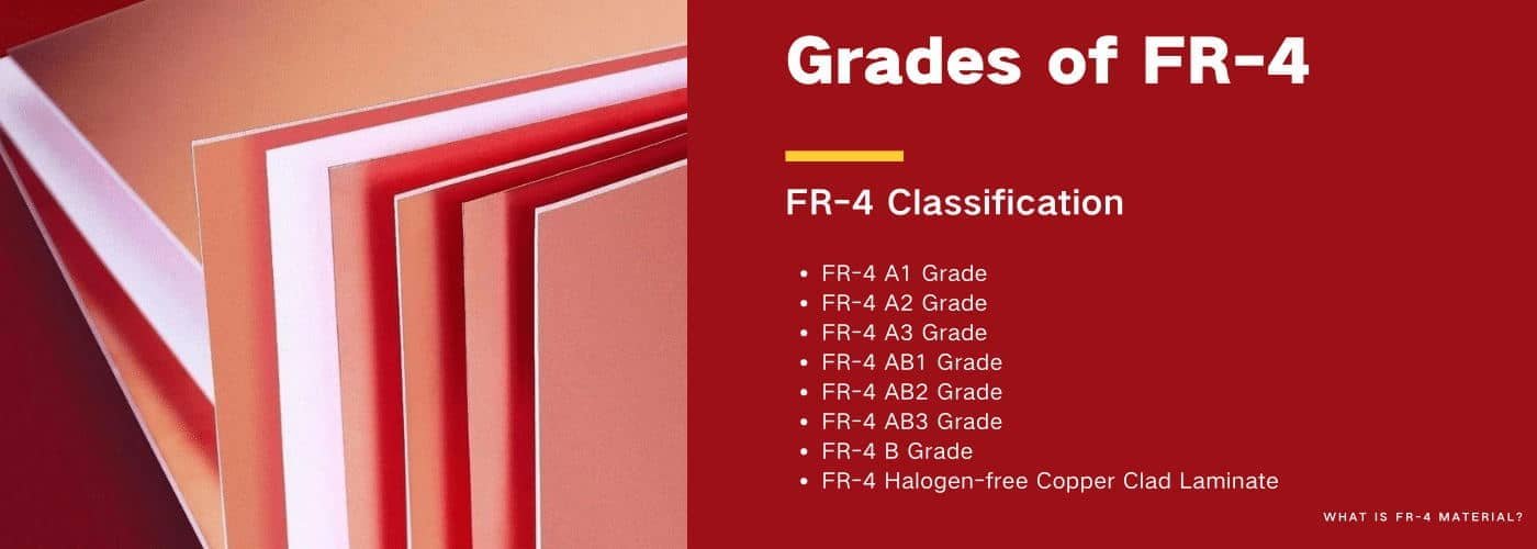
Types of FR-4 PCB Material
FR-4 is not a single material with one fixed performance level. Different FR-4 laminate systems are designed to balance cost, thermal margin, electrical performance, compliance needs, and long-term reliability.
The right choice depends on the PCB’s layer count, assembly profile, operating temperature, signal requirements, copper construction, operating environment, and customer specifications.
Start with Your Application Requirements
Material selection should begin with the conditions your PCB must withstand—not with a generic FR-4 label. Define the thermal profile, layer count, signal speed, impedance targets, voltage, operating environment, compliance requirements, and expected service life before approving a laminate system.
- Assembly temperature and reflow cycles
- Layer count, board thickness, and via structure
- Controlled impedance or high-speed signal needs
- Operating temperature and thermal cycling
- Environmental and compliance requirements
Need help selecting an FR-4 laminate? Talk to an Engineer →
01
Standard Tg FR-4
A cost-effective epoxy-glass laminate for general rigid PCB applications with moderate thermal and reliability demands.
Best for: Consumer electronics, general control boards, standard commercial products, and cost-sensitive designs.
Consider a higher-Tg option when the board will experience lead-free assembly stress, repeated thermal cycling, higher layer counts, or elevated operating temperatures.
02
Mid-Tg FR-4
A balanced material option that provides additional thermal processing margin beyond standard Tg FR-4 while maintaining broad manufacturability.
Best for: Industrial electronics, moderately demanding assemblies, and designs that need a wider thermal margin without moving to a high-Tg system.
Confirm the actual Tg, Td, Z-axis CTE, and assembly profile because “mid-Tg” is a performance category rather than one universal material specification.
03
High-Tg FR-4
A higher-temperature epoxy-glass laminate designed to provide increased thermal margin for demanding assembly processes and reliability-focused PCB applications.
Best for: Lead-free assembly, multilayer PCBs, industrial controls, automotive electronics, high-reliability products, and repeated thermal exposure.
High Tg is valuable, but it should be reviewed together with Td, Z-axis CTE, CAF resistance, moisture performance, stackup design, and operating conditions.
04
High-Speed and Low-Loss FR-4
An optimized epoxy-glass laminate system with more controlled dielectric behavior and lower signal loss than conventional FR-4 grades.
Best for: Controlled-impedance routing, faster digital interfaces, communications equipment, and designs where signal integrity is a material-selection concern.
Evaluate Dk and Df at the relevant frequency, along with glass weave effects, dielectric thickness, copper roughness, trace geometry, and the final impedance stackup.
05
Halogen-Free FR-4
An FR-4 laminate system formulated to meet specified halogen-free material requirements for projects with environmental, customer, or supply-chain compliance needs.
Best for: Customer-approved material lists, environmentally focused programs, and projects with defined halogen-free requirements.
Confirm the exact standard, declaration, customer specification, and required documentation before approval. “Halogen-free” should be verified against the selected material data sheet and compliance documents.
THERMAL MARGIN AND RELIABILITY
Standard FR-4 vs. High-Tg FR-4
Standard FR-4 and high-Tg FR-4 are both epoxy-glass laminate systems used for rigid PCBs. The key difference is the material’s thermal transition behavior and the resulting processing margin under elevated temperatures.
Standard FR-4 can be a practical choice for many cost-sensitive designs with moderate thermal demands. High-Tg FR-4 is often selected when a PCB must tolerate more demanding assembly conditions, repeated thermal stress, higher layer counts, or reliability-focused operating environments.
↔ Swipe horizontally to view the full comparison table.
| Selection Factor | Standard FR-4 | High-Tg FR-4 |
|---|---|---|
| Thermal Processing Margin | Suitable for moderate thermal exposure and standard assembly conditions. | Provides a larger thermal margin for more demanding assembly and operating conditions. |
| Lead-Free Assembly | Can be suitable when the complete material system and assembly profile are appropriate. | Often preferred when lead-free reflow temperatures, multiple reflow cycles, or thermal stress are more demanding. |
| Multilayer PCB Reliability | Suitable for standard multilayer constructions when stackup and reliability demands are moderate. | Commonly selected for more demanding multilayer structures, higher layer counts, and reliability-focused builds. |
| Thermal Cycling | Appropriate for applications with moderate thermal-cycling requirements. | Better suited to applications with more severe or repeated thermal-cycling requirements. |
| Typical Applications | Consumer electronics, standard commercial products, control boards, and cost-sensitive rigid PCBs. | Industrial controls, automotive electronics, higher-layer-count PCBs, lead-free assemblies, and higher-reliability products. |
| Cost Consideration | Usually offers a lower material cost. | Usually carries a higher material cost and should be justified by design, assembly, or reliability needs. |
| Material Review | Confirm Tg, Td, CTE, and assembly compatibility for the selected laminate. | Review Tg together with Td, Z-axis CTE, CAF resistance, moisture performance, stackup, and assembly conditions. |
Note: “High-Tg” is a material category, not a complete reliability guarantee. Actual performance depends on the selected laminate series, stackup, copper distribution, via design, fabrication process, assembly profile, and operating environment.
When Should You Consider High-Tg FR-4?
Consider high-Tg FR-4 when your design involves lead-free assembly, multiple reflow cycles, high layer counts, dense via structures, elevated operating temperatures, demanding thermal cycling, or reliability requirements that exceed the margin of a standard laminate system.
For critical programs, submit the Gerber files, layer stackup, copper weight, assembly profile, operating conditions, and required material approvals for an engineering review before production.
- Thermometer with rising arrow
- Heat waves over PCB layers
- Shield with thermal wave
MATERIAL FIT FOR YOUR APPLICATION
When Is FR-4 the Right PCB Material?
FR-4 is the preferred material for many rigid PCB designs because it offers a practical balance of electrical insulation, mechanical strength, thermal performance, manufacturing flexibility, and cost.
It is often the right starting point for standard and moderately demanding applications. However, the material should be evaluated against the actual electrical, thermal, mechanical, and environmental requirements of the finished product.
Choose FR-4 When Your Project Needs:
FR-4 is a practical and widely available choice for rigid PCBs that need proven performance without the cost or complexity of specialized substrate systems.
- A cost-effective rigid PCB substrate for prototype through production builds
- Reliable electrical insulation and mechanical stability
- Standard to moderately demanding thermal performance
- Single-sided, double-sided, or multilayer PCB construction
- General controlled-impedance requirements within an appropriate FR-4 stackup
- Consumer electronics, industrial controls, power products, and general communications hardware
- Broad laminate availability and established fabrication processes
Consider Another PCB Material When Your Project Needs:
A specialized laminate or substrate may be more appropriate when electrical performance, thermal management, mechanical flexibility, or operating conditions exceed the practical range of conventional FR-4.
- Very low dielectric loss for high-frequency RF or microwave applications
- Stable electrical performance at very high operating frequencies
- Flexible, dynamic-bend, or compact three-dimensional circuit construction
- Continuous exposure to unusually high temperatures
- Enhanced heat dissipation through a metal-backed or thermally conductive substrate
- Specialized low-Dk, low-Df, ceramic-filled, PTFE, polyimide, or metal-core material properties
Material Selection Should Follow the Application—not a Single Specification
Some higher-speed, higher-frequency, or thermally demanding designs can still use carefully selected FR-4 systems. The final decision should consider operating frequency, signal-loss budget, impedance targets, temperature exposure, power dissipation, layer count, copper construction, assembly profile, and reliability requirements.
BUILD THE RIGHT PCB STRUCTURE
FR-4 Thickness, Copper Weight, and PCB Stackup
Finished board thickness is only one part of an FR-4 PCB specification. A complete stackup defines the layer count, copper weight, core thickness, prepreg construction, dielectric spacing, and final finished thickness needed to support the mechanical, electrical, and thermal requirements of the design.
A “1.6 mm FR-4 PCB” does not describe one universal construction. Different core and prepreg combinations can produce the same nominal thickness while delivering different impedance behavior, resin flow, copper balance, thermal performance, and manufacturing reliability.
Share These Design Inputs
Providing the following information helps engineering teams recommend a manufacturable FR-4 construction and evaluate material suitability before fabrication.
- Layer count and target finished board thickness
- Outer and inner copper weight requirements
- Controlled impedance targets and reference layers
- Signal speed, frequency range, or loss-budget requirements
- High-current paths and thermal constraints
- Via structure, HDI requirements, and BGA pitch
- Assembly profile and expected reflow cycles
- Operating environment and required material approvals
Gerber files, a layer stackup, and impedance notes provide the fastest path to an accurate engineering review.
How Thickness and Copper Weight Affect PCB Design
Board thickness and copper weight influence mechanical stiffness, connector fit, current capacity, thermal behavior, trace geometry, and fabrication complexity. In multilayer boards, dielectric thickness between copper layers is especially important because it affects impedance and signal integrity.
Heavier copper can improve current-carrying capability and heat spreading, but it also changes etching behavior, minimum trace geometry, resin-flow requirements, and the final stackup. Thin boards, heavy copper, high layer counts, fine-pitch components, and controlled impedance often require an engineered construction rather than a generic material callout.
Finished Board Thickness
Defines mechanical fit, stiffness, connector compatibility, enclosure clearance, and handling requirements. The finished thickness must be achieved through a manufacturable combination of cores, prepregs, copper, plating, and surface finish.
Copper Weight
Influences current capacity, temperature rise, heat spreading, etching compensation, and minimum trace-and-space capability. Outer and inner copper layers may require different weights.
Dielectric Thickness
The spacing between a signal layer and its reference plane strongly affects impedance. It should be defined through the final pressed prepreg and core construction, not only by nominal board thickness.
Controlled Impedance
Impedance depends on trace geometry, copper thickness, dielectric thickness, material Dk, solder mask, reference planes, and the approved production stackup.
Layer Count and Via Structure
More layers, buried or blind vias, HDI features, and dense BGA routing can increase lamination complexity and influence material selection, registration, resin flow, and reliability planning.
Thermal and Mechanical Requirements
High current, repeated thermal cycling, elevated operating temperature, board flexing, and mechanical mounting needs should be evaluated alongside material grade, copper construction, and board thickness.
Need a Manufacturable FR-4 Stackup?
Send your Gerber files, target board thickness, layer count, copper weights, impedance requirements, assembly profile, and quantity. Our engineering team can review the stackup and recommend a practical FR-4 material construction for fabrication.
Related capabilities: Multilayer PCB Manufacturing · Controlled Impedance PCB · Heavy Copper PCB
A PRACTICAL ENGINEERING CHECKLIST
How to Select the Right FR-4 Material
The right FR-4 material is selected by matching the laminate system to the electrical, thermal, mechanical, assembly, and compliance requirements of the finished PCB—not by choosing a generic FR-4 grade alone.
Use the checklist below to define your requirements before releasing a design for fabrication. For critical applications, confirm the final laminate series, approved data sheet, and production stackup with your PCB manufacturer before production.
What to Send With Your RFQ
The more complete the design information, the more accurately engineering can recommend an FR-4 laminate system and production stackup.
- Gerber files or ODB++ data
- Layer count and target finished thickness
- Outer and inner copper weights
- Impedance targets and controlled layers
- Assembly profile and reflow requirements
- Operating temperature and environment
- Required approvals, compliance documents, or AVL
Define the Operating Temperature and Thermal Cycling
Identify the maximum operating temperature, expected thermal cycling, and any sustained heat exposure. These conditions influence the required thermal margin and help determine whether standard, mid-Tg, or high-Tg FR-4 should be evaluated.
01
Define the Operating Temperature and Thermal Cycling
Identify the maximum operating temperature, expected thermal cycling, and any sustained heat exposure. These conditions influence the required thermal margin and help determine whether standard, mid-Tg, or high-Tg FR-4 should be evaluated.
02
Confirm the Assembly Process
Specify whether the board will use lead-free assembly, the expected reflow temperature profile, the number of reflow cycles, and any rework exposure. Assembly conditions can place substantial thermal stress on the laminate and plated-through-hole structure.
03
Define Layer Count, Thickness, and Via Structure
Confirm the layer count, finished thickness, copper distribution, through-hole or microvia structure, BGA density, and HDI requirements. These factors affect lamination complexity, resin flow, registration, Z-axis reliability, and material construction.
04
Identify Signal and Impedance Requirements
For controlled-impedance, high-speed, RF, or higher-frequency designs, identify the target impedance, signal speed or frequency range, loss budget, reference planes, and critical routing layers. Dk, Df, glass weave, copper roughness, and pressed dielectric thickness may all matter.
05
Review Copper Weight and Power Requirements
Define the required outer and inner copper weights, current-carrying paths, allowable temperature rise, and heat-spreading needs. Copper construction influences etching, resin flow, trace geometry, dielectric spacing, and the final stackup.
06
Evaluate the Operating Environment
Consider humidity, contamination, vibration, mechanical loading, voltage stress, corrosion exposure, and expected product service life. These conditions can influence moisture resistance, CTI, CAF resistance, material durability, and long-term reliability requirements.
07
Confirm Compliance and Material Approval Requirements
Check whether the design requires halogen-free materials, customer-approved laminate families, UL documentation, IPC material classification, specific declarations, or an approved vendor list. Include the relevant specifications and documents with the RFQ.
08
Approve the Final Laminate Data Sheet and Stackup
Before release to production, confirm the approved laminate series, key material properties, final layer construction, copper weights, dielectric thicknesses, impedance model, and any required alternates. This helps align design intent with fabrication capability and supply availability.
A Material Name Alone Is Not a Complete PCB Specification
For a reliable quotation and manufacturability review, provide the application requirements together with the PCB design data. Engineering can then confirm whether a standard FR-4, high-Tg FR-4, halogen-free FR-4, low-loss FR-4, or another material system is the most practical fit.
MATERIAL SOURCING AND DOCUMENTATION
FR-4 Laminate Brands and Material Options
FR-4 material selection should be based on the required performance, approved supplier requirements, laminate construction, documentation needs, production volume, and current material availability.
PCBELEC can review standard FR-4, mid-Tg, high-Tg, halogen-free, high-CTI, and application-specific epoxy-glass laminate options based on your PCB design and sourcing requirements. If your project specifies an approved manufacturer, material series, IPC classification, UL requirement, or customer AVL, include it with your RFQ for engineering review.
Availability Is Part of Material Selection
Material availability can vary by laminate series, core thickness, prepreg style, resin content, copper foil type, regional supply conditions, order quantity, and required lead time. Final material approval should be confirmed before production release.
Standard FR-4
A practical epoxy-glass laminate option for general rigid PCB applications where cost efficiency, established processing, and moderate thermal performance are the primary requirements.
Best fit: General rigid PCB applications
Mid-Tg and High-Tg FR-4
Higher thermal-margin laminate systems for lead-free assembly, multilayer construction, repeated thermal exposure, and reliability-focused applications.
Halogen-Free FR-4
Material options for projects with defined halogen-free, environmental, customer, or supply-chain compliance requirements.
Review: Required standards and declarations
High-CTI FR-4
Laminate options designed for applications where resistance to electrical tracking and insulation coordination are important considerations.
Best fit: Higher-voltage and reliability-sensitive designs
Low-Loss and High-Speed FR-4
Optimized epoxy-glass laminate systems for controlled impedance and signal-integrity requirements where dielectric behavior and loss need closer evaluation.
Customer-Specified Materials
Support for customer-approved laminate manufacturers, material series, IPC slash sheets, UL files, AVL requirements, and documentation requests, subject to technical review and supply availability.
Review: Include requirements with your RFQ
Specifying a Particular FR-4 Laminate?
To review a specified material accurately, provide the laminate manufacturer, material series, core and prepreg construction, copper foil requirement, required Tg/Td/Dk/Df or CTI values, IPC slash sheet where applicable, UL or compliance documentation, approved alternates, and target production quantity.
FROM MATERIAL SELECTION TO PCB FABRICATION
FR-4 PCB Manufacturing at PCBELEC
PCBELEC supports FR-4 PCB fabrication from prototype through production, with material and stackup options reviewed against the electrical, thermal, mechanical, assembly, and sourcing requirements of each project.
Before fabrication, our engineering team reviews the available design data, including Gerber files, layer count, finished thickness, copper weight, stackup, impedance requirements, via structure, and material specifications. This helps align the selected FR-4 laminate system with manufacturability, reliability, and production requirements.
Prototype to Production
Support for FR-4 PCB programs from early prototypes and engineering validation through repeat production, subject to the approved material construction and project requirements.
FR-4 Material Selection
Review of standard, mid-Tg, high-Tg, halogen-free, high-CTI, and application-specific epoxy-glass laminate options based on design needs and material availability.
Multilayer PCB Construction
Support for rigid PCB constructions that require multiple FR-4 cores, prepregs, inner copper layers, and an engineered lamination stackup.
Stackup and DFM Review
Engineering review of layer construction, finished thickness, copper distribution, dielectric spacing, via structure, and fabrication considerations before production release.
Controlled Impedance Support
Review of target impedance, routing layers, reference planes, trace geometry, dielectric construction, and verification requirements as specified for the project.
Copper and Thermal Options
Evaluation of copper weight, copper distribution, current-carrying paths, resin-flow considerations, and thermal requirements for standard and higher-current FR-4 designs.
Surface Finish and Assembly Readiness
Surface finish options and fabrication details can be reviewed in relation to solderability, component assembly, storage conditions, and product requirements.
Documentation and Traceability Support
Material documentation, inspection requirements, and traceability expectations can be reviewed when specified in the quotation request or purchase documentation.
How We Review an FR-4 PCB Project
1. Review Design Data
Gerber files, drawings, layer count, and material requirements.
2. Confirm Material and Stackup
Laminate options, copper construction, dielectric spacing, and availability.
3. Check Manufacturability
DFM considerations, via structure, copper balance, and assembly needs.
4. Release for Fabrication
Approved construction, production requirements, and required documentation.
Ready to Build Your FR-4 PCB?
Send your Gerber files, target board thickness, layer count, copper requirements, stackup, impedance targets, material preferences, and quantity. We will review the available information and help define a practical path to fabrication.
For material-controlled or impedance-critical projects, include the required laminate series, approved alternates, and documentation needs.
Related services: Rigid PCB Manufacturing · Multilayer PCB · Controlled Impedance PCB · Heavy Copper PCB
FR-4 MATERIAL QUESTIONS ANSWERED
FR-4 Material FAQs
Explore answers to common questions about FR-4 PCB material, including its meaning, thermal performance, high-Tg options, thickness, high-frequency suitability, lead-free assembly, and specified laminate requirements.
FR-4 is a flame-retardant, glass-reinforced epoxy laminate widely used as the insulating substrate in rigid printed circuit boards. In PCB fabrication, it commonly serves as the dielectric material between copper layers and provides electrical insulation, mechanical strength, and dimensional stability.
FR-4 is a material category rather than one identical formulation. Its thermal, electrical, and mechanical properties vary by laminate manufacturer, resin system, glass style, resin content, copper construction, and test method.
No. FR-4 is usually the insulating laminate material used inside a rigid PCB, not the finished PCB itself. A completed PCB also includes patterned copper circuits, drilled or plated holes, solder mask, a surface finish, markings, and other fabrication features.
In multilayer construction, FR-4 cores and prepregs are combined with copper layers to create the final board stackup.
High-Tg FR-4 uses a laminate system with a higher glass transition temperature, giving the material a larger thermal processing margin than standard FR-4. It is often evaluated for lead-free assembly, repeated reflow, multilayer boards, elevated operating temperatures, and reliability-focused applications.
A higher Tg alone does not define total reliability. Td, Z-axis CTE, CAF resistance, moisture behavior, copper construction, via structure, stackup, assembly profile, and operating conditions should also be reviewed.
FR-4 is available in several Tg categories. Standard grades are commonly around 130–150°C, mid-Tg grades are often around 150–170°C, and high-Tg grades are generally 170°C or higher.
These ranges are general selection guidance, not release criteria. Confirm the exact Tg test method and value using the selected laminate manufacturer’s current data sheet.
Some FR-4 systems can support controlled-impedance and moderate-frequency designs when the stackup, dielectric construction, copper characteristics, and trace geometry are engineered appropriately. However, conventional FR-4 may not provide the low loss or electrical stability required for very high-frequency RF, microwave, or low-loss signal applications.
For these designs, evaluate Dk and Df at the relevant frequency together with glass weave effects, copper roughness, signal-loss budget, and impedance requirements. A specialized low-loss, hydrocarbon-ceramic, PTFE, or other high-frequency material may be more appropriate.
FR-4 PCBs can be fabricated in a range of finished thicknesses using different combinations of cores, prepregs, copper weights, plating, solder mask, and surface finishes. Common thicknesses are widely used, but a nominal thickness alone does not define the complete PCB construction.
For multilayer, heavy-copper, controlled-impedance, HDI, or reliability-critical designs, confirm the final finished thickness through an approved production stackup rather than selecting material by thickness alone.
FR-4 can be suitable for lead-free assembly, but the material must be selected against the actual reflow profile, number of assembly cycles, board thickness, layer count, copper construction, via structure, and reliability requirements.
High-Tg FR-4 is often considered when lead-free processing creates greater thermal stress, particularly in multilayer or reliability-focused applications. Confirm the selected material’s Tg, Td, Z-axis CTE, moisture behavior, and assembly compatibility before production release.
Yes. Include the laminate manufacturer, material series, required properties, core and prepreg construction, copper foil requirement, applicable IPC classification, UL or compliance documentation, approved alternates, and target quantity with your RFQ.
The requested material should then be reviewed against the final stackup, manufacturing requirements, supply availability, and lead time before approval for production.
Still Need Help Selecting an FR-4 Material?
Share your Gerber files, layer stackup, material requirements, assembly conditions, and target quantity. Our engineering team can help review the practical laminate and stackup options for your project.Lorem ipsum dolor sit amet, consectetur adipiscing elit. Ut elit tellus, luctus nec ullamcorper mattis, pulvinar dapibus leo.
START YOUR FR-4 PCB PROJECT
Need Help Selecting FR-4 PCB Material?
Send your PCB design files and project requirements for a practical material and stackup review. Our engineering team can help evaluate the appropriate FR-4 laminate system, finished thickness, copper construction, impedance stackup, and fabrication approach for your application.
For material-controlled, impedance-critical, or reliability-focused designs, include your required laminate series, approved alternates, documentation needs, and assembly conditions.
What to Include With Your RFQ
The following information helps us review material suitability, stackup feasibility, and manufacturing requirements more accurately.
- Gerber, ODB++, or other fabrication data
- Layer count and target finished board thickness
- Outer and inner copper weight requirements
- Stackup details and controlled impedance targets
- Material preferences, approved vendors, or AVL requirements
- Surface finish, solder mask, and fabrication notes
- Target quantity, delivery requirements, and project timeline
- Assembly profile, operating environment, and reliability requirements