Copper Clad Laminate (CCL): Types, Properties and PCB Material Selection
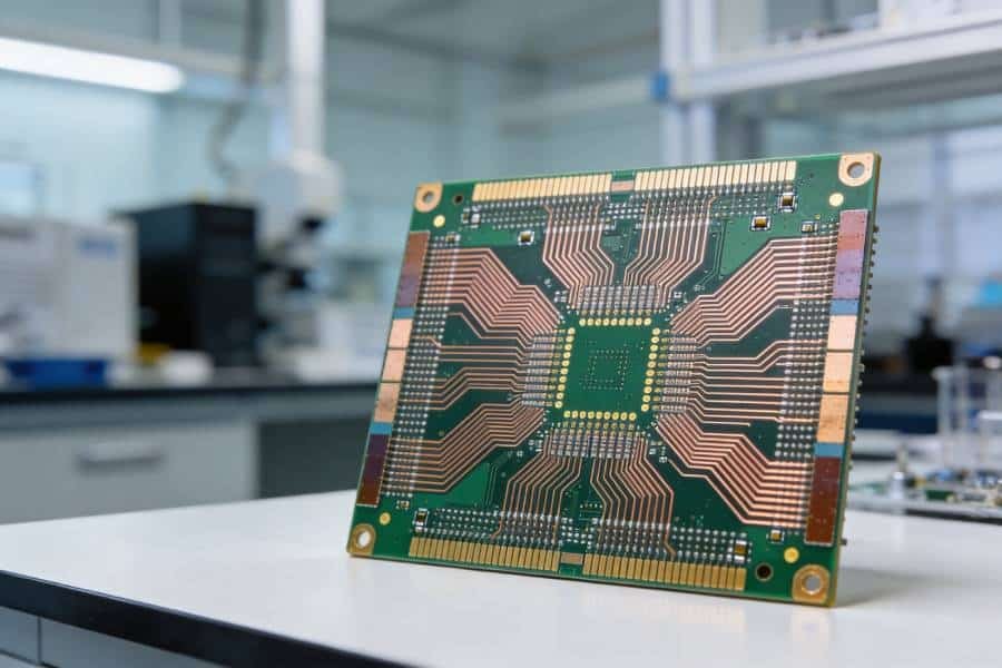
Copper clad laminate (CCL) is the foundational material used to manufacture printed circuit boards. It combines conductive copper foil with an insulating dielectric substrate, creating the base from which circuit traces, pads, planes and interconnections are formed.
The right laminate choice affects electrical performance, impedance stability, signal loss, heat dissipation, assembly reliability and total PCB cost. This guide explains the main types of CCL, the material properties that matter most, and how to select a practical material system for rigid, flexible, metal-core, high-speed and RF PCB applications.
What Is Copper Clad Laminate?
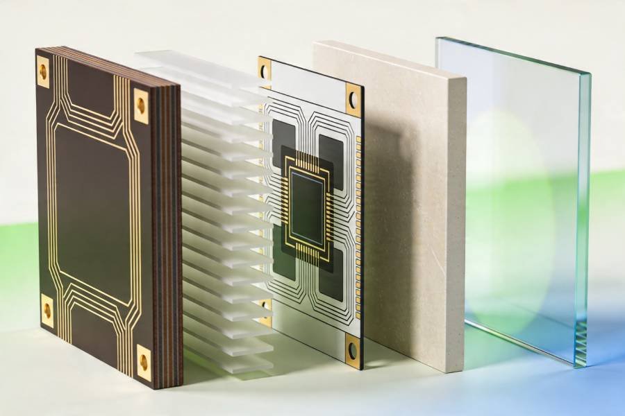
Copper clad laminate, commonly abbreviated as CCL, is a composite base material formed by bonding copper foil to one or both sides of an electrically insulating substrate. The substrate may use epoxy resin and woven glass fabric, polyimide film, PTFE-based compounds, metal-core structures or other engineered dielectric systems, depending on the intended PCB application.
During PCB fabrication, the copper foil is selectively patterned and etched to create conductive features such as traces, pads, ground planes and power planes. The dielectric portion provides electrical insulation, mechanical support and defined thermal behavior. In other words, CCL is the starting material for a PCB—it is not the completed circuit board.
For multilayer PCB construction, copper-clad laminate is commonly used as a core. It is combined with prepreg during lamination to build the final stack-up. Prepreg is a partially cured, resin-impregnated bonding material that flows under heat and pressure to bond layers together; it should not be confused with the woven glass reinforcement itself.
Electrical Foundation
Copper foil provides the conductive layer used to create PCB traces, pads, vias and electrical planes.
Insulating Base
The dielectric system separates conductive layers while providing mechanical strength and electrical insulation.
Material Options
Common systems include FR-4, high-Tg epoxy, polyimide, PTFE-based materials and metal-core laminates.
Performance Impact
Material selection influences signal integrity, thermal reliability, moisture resistance, manufacturability and cost.
How Copper Clad Laminate Is Constructed
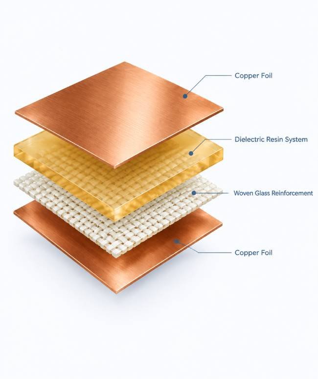
The construction of a copper clad laminate depends on the required electrical, thermal and mechanical performance. However, most CCL systems include a conductive copper layer and a dielectric base that has been engineered for a specific PCB manufacturing process.
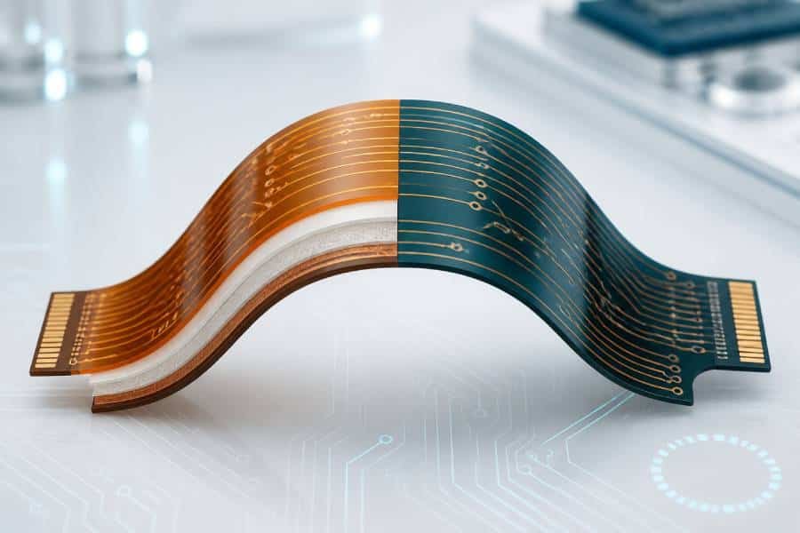
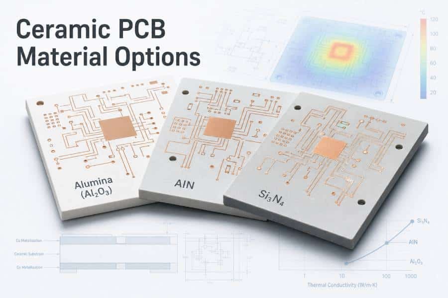
In a typical double-sided rigid laminate, copper foil is bonded to both sides of a glass-reinforced epoxy substrate. In flexible circuits, a thin polyimide film is usually combined with rolled-annealed or electrodeposited copper. In metal-core PCB structures, the dielectric layer is paired with an aluminum or copper base to improve thermal transfer.
- Copper foil: forms the conductive pattern after imaging and etching.
- Dielectric resin system: provides electrical insulation, bonding strength and thermal behavior.
- Reinforcement or base material: may include woven glass, polyimide film, aramid, ceramic-filled resin or a metal substrate.
- Optional second copper layer: creates a double-sided laminate suitable for multilayer PCB construction or double-sided circuit designs.
Important: In multilayer PCB fabrication, a copper-clad laminate can function as a core, while prepreg is used as the bonding material between layers during the lamination cycle. The final stack-up must be designed as a complete system—not as a collection of isolated material values.
Main Types of Copper Clad Laminate
CCL materials are selected according to the operating environment, electrical design, thermal load, mechanical requirements and production process. The categories below provide a practical starting point for selecting the right direction for a PCB project.
FR-4 and Standard Rigid CCL
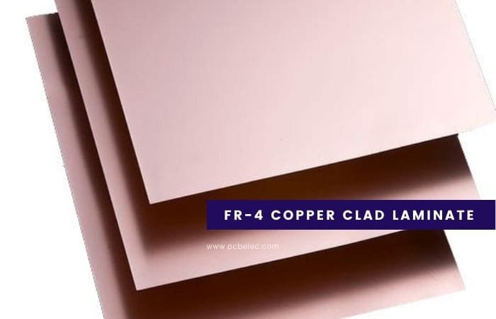
FR-4 is the most widely used dielectric family for rigid PCBs. It generally combines woven glass reinforcement with an epoxy resin system and copper foil. Standard FR-4 laminates provide a practical balance of electrical insulation, mechanical strength, process compatibility and cost for a broad range of electronic products.
They are commonly used for consumer electronics, industrial controls, power supplies, instrumentation and general-purpose multilayer boards. However, “FR-4” is a material category rather than a single universal specification. Properties such as Tg, Dk, Df, resin content, copper adhesion, thermal reliability and flame behavior vary by laminate grade and supplier.
For standard rigid PCB projects, material selection should still consider the finished board thickness, copper weight, layer count, assembly temperature, impedance needs and reliability target.
Explore rigid PCB manufacturing options and request a manufacturability review for your FR-4 stack-up.
High-Tg and High-Reliability CCL
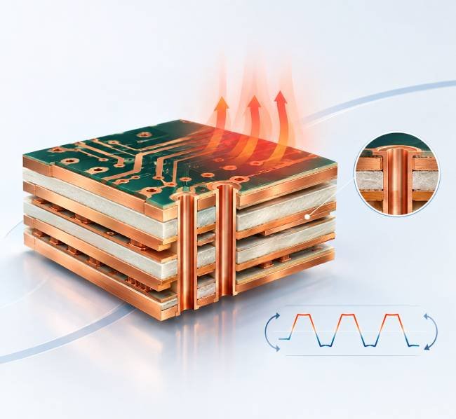
High-Tg laminates are designed for applications that experience elevated assembly temperatures, repeated thermal cycling or demanding long-term operating conditions. Their higher glass-transition temperature can help maintain mechanical stability when standard materials approach their thermal limits.
High-Tg material selection is especially relevant for multilayer PCBs, lead-free assembly, automotive electronics, industrial systems and designs with high copper density or sustained heat exposure. However, Tg alone does not define reliability. Engineers should also evaluate decomposition temperature (Td), Z-axis coefficient of thermal expansion, delamination resistance, CAF resistance, moisture absorption and compatibility with the complete stack-up.
A high-reliability PCB material system should be selected according to the application environment and assembly profile rather than by a single headline parameter.
High-Speed and RF / Microwave CCL
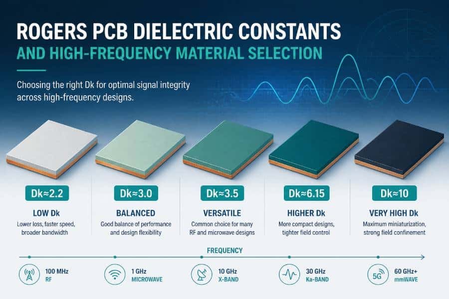
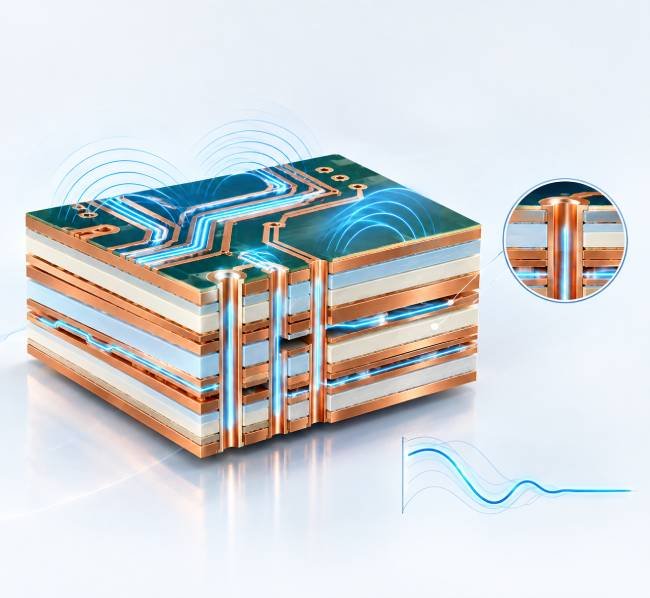
High-speed digital, RF and microwave designs often require laminate systems with controlled dielectric properties and lower electrical loss than general-purpose materials. In these applications, material behavior can directly affect impedance control, insertion loss, phase stability, timing margin and overall signal integrity.
The most important considerations usually include dielectric constant (Dk), dissipation factor (Df), Dk stability across frequency and temperature, copper foil roughness, resin consistency, thermal expansion and processing compatibility. The correct choice depends on the actual frequency range, trace geometry, loss budget, impedance requirement and fabrication stack-up.
Low-loss laminate selection should be confirmed with the PCB manufacturer before release, particularly where controlled impedance, hybrid stack-ups, RF transitions or fine-pitch structures are involved.
Explore high-frequency PCB manufacturing or discuss controlled-impedance requirements.
Metal-Core CCL for Thermal Management
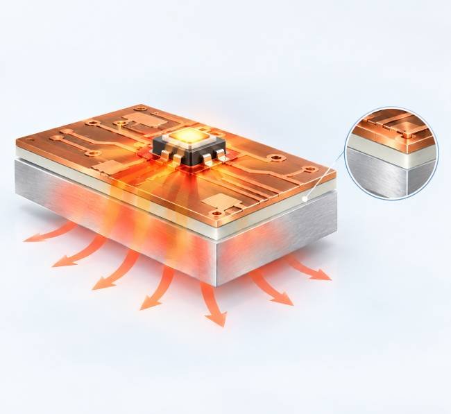
Metal-core laminates are commonly used where heat must be transferred efficiently away from components. These structures typically combine a copper circuit layer, a thermally conductive dielectric layer and a metal base—often aluminum or copper.
They are widely used in LED lighting, power conversion, automotive lighting, motor-control systems and other thermal-management applications. The metal base can provide a useful heat-spreading path, but final thermal performance depends on more than the base metal. The dielectric layer, copper area, thermal resistance, component interface, mounting design and airflow must all be considered together.
Metal-core PCB construction should therefore be reviewed as a complete thermal path rather than as a material substitution alone.
Flexible Copper Clad Laminate
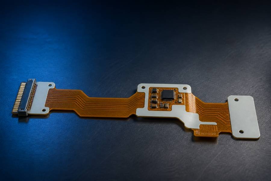
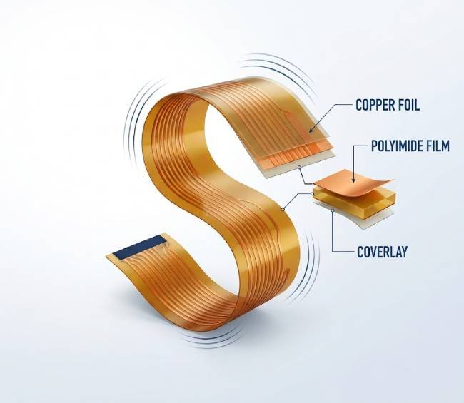
Flexible copper clad laminate, often called FCCL, is used to manufacture flexible printed circuits and rigid-flex PCBs. It commonly combines thin polyimide film with copper foil and may use either adhesive-based or adhesiveless construction, depending on the design and reliability requirement.
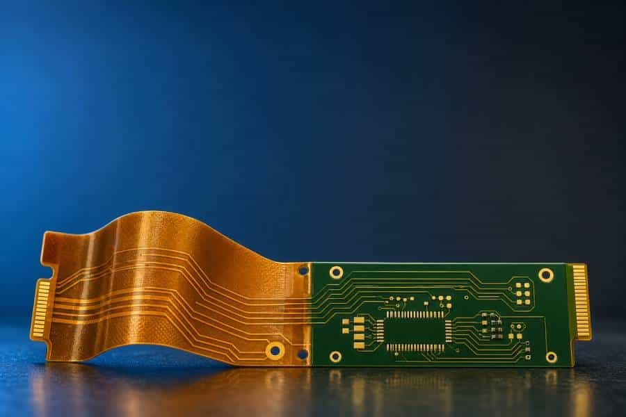
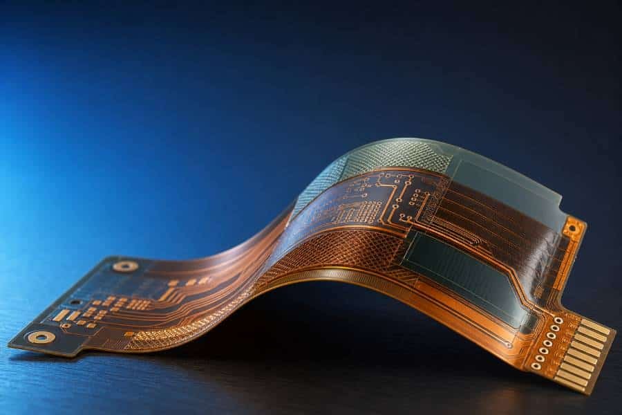
Flexible PCB materials must support bending, folding, dynamic flexing or compact three-dimensional packaging while maintaining conductor integrity. Important considerations include copper foil type, bend radius, dynamic-flex cycles, coverlay construction, stiffener requirements, adhesive system, dimensional stability and impedance control.
For repeated bending applications, material selection and bend-zone design should be reviewed together. A suitable flex laminate cannot compensate for poor bend geometry, unsuitable trace routing or improper stiffener placement.
Explore flexible PCB manufacturing and rigid-flex PCB solutions.
How to Select a CCL for Your PCB Application
The table below provides a practical starting point for matching common PCB requirements with a suitable laminate direction. Final material approval should be based on the complete stack-up, electrical requirements, assembly profile, compliance needs and availability.
| Application or Design Need | Typical CCL Direction | Key Properties to Evaluate | Related PCB Solution |
|---|---|---|---|
| General electronics and standard control boards | Standard FR-4 laminate | Tg, board thickness, copper weight, flame rating, cost | Rigid PCB Manufacturing |
| Multilayer PCBs and lead-free assembly | High-Tg or high-reliability FR-4 | Tg, Td, Z-axis CTE, thermal cycling, CAF resistance | Multilayer PCB Manufacturing |
| High-speed digital designs | Low-loss laminate | Dk, Df, copper roughness, impedance stability, frequency response | Controlled-Impedance PCB |
| RF, microwave and antenna applications | RF / microwave laminate | Dk stability, Df, thermal coefficient of Dk, copper profile | High-Frequency PCB |
| LED lighting and power electronics | Aluminum or copper-base metal-core laminate | Thermal resistance, dielectric strength, thermal path, copper area | Metal-Core PCB |
| Dynamic bending and compact interconnects | Polyimide FCCL | Bend life, copper type, coverlay, adhesive system, bend radius | Flexible PCB |
| Rigid-flex and three-dimensional packaging | Rigid CCL combined with FCCL | Stack-up compatibility, lamination design, bend-zone reliability | Rigid-Flex PCB |
| High-voltage or harsh-environment electronics | Specialized high-reliability laminate | CTI, moisture absorption, insulation reliability, thermal stability | Custom PCB Manufacturing |
Key CCL Properties That Influence PCB Performance
CCL material selection should be based on the complete electrical, thermal and mechanical requirement of the PCB. The properties below are among the most important when comparing laminate systems. Actual values vary by resin system, glass style, copper construction, test method, frequency and supplier datasheet.
| Property | What It Means | Why It Matters for PCB Performance | Most Relevant Applications |
|---|---|---|---|
| Tg Glass Transition Temperature | The temperature range at which the resin system changes from a rigid, glass-like state to a more compliant state. | Influences thermal stability during soldering, thermal cycling and long-term operation. Higher Tg can help reduce softening and dimensional change at elevated temperatures. | Multilayer PCBs, lead-free assembly, automotive electronics, industrial controls |
| Td Decomposition Temperature | The temperature at which the laminate begins to undergo significant thermal decomposition. | Helps indicate resistance to high-temperature assembly exposure, rework and demanding thermal environments. It should be assessed together with the full reliability profile. | Lead-free reflow, high-temperature electronics, multilayer PCBs |
| Dk Dielectric Constant | A measure of how the dielectric material affects electric-field propagation through the PCB structure. | Influences impedance, signal propagation speed and timing. For high-speed and RF designs, Dk should be reviewed at the relevant operating frequency. | Controlled-impedance PCBs, high-speed digital, RF and microwave circuits |
| Df Dissipation Factor | A measure of dielectric loss, also known as loss tangent. | Lower Df generally helps reduce signal attenuation and insertion loss, especially as frequency and trace length increase. | RF, microwave, antennas, high-speed digital interconnects |
| CTE Coefficient of Thermal Expansion | A measure of how much the laminate expands or contracts as temperature changes. | Z-axis CTE is particularly important because excessive expansion can place stress on plated through holes, vias and multilayer interconnections. | Multilayer PCBs, HDI PCBs, thermal-cycling applications, high-reliability electronics |
| Peel Strength | The bond strength between the copper foil and the dielectric substrate. | Supports copper adhesion through fabrication, assembly, rework and field use. The appropriate level depends on copper weight, circuit geometry and processing requirements. | Heavy-copper PCBs, high-reliability boards, flexible circuits, rework-sensitive assemblies |
| Thermal Conductivity | The ability of a material to transfer heat. | Important for removing heat from power devices and LEDs. Actual system performance also depends on dielectric thickness, copper area, thermal interfaces and mechanical mounting. | Metal-core PCBs, LED PCBs, power electronics, automotive lighting |
| Moisture Absorption | The tendency of the laminate to absorb moisture from its environment. | Moisture can affect insulation resistance, dimensional stability and resistance to thermal stress. Low absorption may be important in harsh or humidity-sensitive environments. | Outdoor electronics, aerospace, high-reliability assemblies, sensitive RF systems |
| CTI Comparative Tracking Index | A measure of resistance to conductive tracking across an insulating material surface under electrical stress and contamination. | Higher CTI can support creepage and insulation reliability in high-voltage or contaminated operating environments. | High-voltage power supplies, industrial controls, automotive electronics |
| Copper Foil Type and Roughness | The copper foil construction and surface profile, such as electrodeposited (ED) or rolled-annealed (RA) copper. | Can affect conductor adhesion, high-frequency loss, etching behavior and flex life. Copper selection should match both signal-performance and mechanical requirements. | High-frequency PCBs, flexible PCBs, rigid-flex PCBs, fine-line circuits |
A Practical PCB Laminate Selection Process
Choosing a PCB laminate is not simply a matter of selecting the highest Tg or the lowest Dk. A reliable decision balances electrical performance, thermal stress, mechanical design, fabrication capability, material availability and project cost.
Define Electrical Requirements
Identify whether the design requires controlled impedance, high-speed digital performance, RF or microwave behavior, high-voltage insulation, low dielectric loss or specific signal-integrity targets.
Evaluate Thermal Conditions
Review the assembly profile, peak reflow temperature, continuous operating temperature, power density, thermal cycling conditions and component heat load.
Confirm Mechanical Requirements
Define finished board thickness, copper weight, layer count, dimensional stability, bend requirements, vibration exposure and any stiffener or mounting constraints.
Build a Manufacturable Stack-Up
Review core and prepreg construction, impedance geometry, resin flow, drill structure, plated-hole reliability and fabrication tolerances as one integrated stack-up.
Balance Reliability, Availability and Cost
Select a material system that meets the real application requirement while considering qualified alternatives, material lead time, volume demand, certification needs and total manufacturing cost.
Need Help Selecting a PCB Laminate?
Share your Gerber files, layer stack-up, controlled-impedance requirements, operating environment, assembly process and expected volume. Our engineering team can help review the material direction and identify a practical PCB fabrication solution for your project.
Related PCB Manufacturing Capabilities
Material selection works best when it is reviewed together with the intended PCB structure and manufacturing process. Explore the PCB solutions below or contact our team with your stack-up requirement.
Rigid PCB Manufacturing
FR-4 and other rigid laminate options for single-sided, double-sided and multilayer PCB projects.
High-Tg PCB Manufacturing
Material systems designed for elevated assembly temperatures, multilayer construction and demanding thermal conditions.
High-Frequency PCB Manufacturing
Low-loss material options and controlled-impedance stack-ups for RF, microwave and high-speed applications.
Metal-Core PCB Manufacturing
Aluminum and copper-base PCB structures for LED, power and thermal-management applications.
Flexible PCB Manufacturing
Polyimide-based flexible circuits for compact packaging, bend-to-install structures and dynamic-flex applications.
Rigid-Flex PCB Manufacturing
Integrated rigid and flexible structures for three-dimensional packaging, reduced connectors and compact electronic assemblies.
Copper Clad Laminate FAQ
No. Copper clad laminate is the broader term for an insulating substrate laminated with copper foil. FR-4 is one common rigid dielectric material category used to produce copper clad laminates. Depending on the application, CCL may also use polyimide, PTFE-based materials, metal-core structures or other specialty dielectric systems.
CCL is a copper-clad dielectric material. In multilayer PCB manufacturing, a copper-clad laminate often serves as a core because it already includes copper foil on one or both sides. Prepreg is a partially cured resin-impregnated material used to bond layers during lamination. The final PCB stack-up combines cores, prepregs and copper layers according to the design requirement.
The selection depends on the assembly temperature, layer count, thermal cycling requirement, operating environment and reliability target. High-Tg FR-4 may offer improved thermal stability, but the decision should also consider Td, Z-axis CTE, CAF resistance, moisture behavior, resin system and the full PCB stack-up.
High-frequency designs generally require a laminate with controlled dielectric constant, low dissipation factor, stable electrical performance across the working frequency range and appropriate copper foil characteristics. The best choice depends on operating frequency, loss budget, impedance target, stack-up geometry, thermal requirement and fabrication process.
Not always. An aluminum base can provide an effective heat-spreading path, but overall thermal performance also depends on the dielectric layer, copper layout, component thermal interface, board mounting, heat sink design and airflow. The entire thermal path should be evaluated.
ED copper foil is electrodeposited copper, while RA copper foil is rolled-annealed copper. Their grain structures, surface characteristics, flexibility and processing behavior differ. RA copper is often preferred in applications requiring repeated flexing, while the best choice depends on the circuit design, fabrication process and performance requirement.
Useful information includes Gerber files, layer count, finished board thickness, copper weight, controlled-impedance requirements, operating temperature, assembly profile, application environment, compliance needs, expected volume and target lead time. A preliminary stack-up is also helpful for multilayer, RF and high-speed PCB projects.
In many cases, a manufacturer can suggest an equivalent or alternative material direction based on the required electrical, thermal and mechanical performance. Final approval should be based on the applicable datasheets, stack-up review, qualification requirements and the customer’s design validation process.
Start Your PCB Material Review
Send us your Gerber files, material requirements or preliminary stack-up. Our team can help evaluate a practical laminate direction for prototype and production PCB fabrication, including rigid, flexible, metal-core, high-speed and RF applications.
- Gerber files or design data
- Stack-up and impedance requirements
- Prototype or production volume