PCB MATERIALS / THERMAL MANAGEMENT
Aluminum PCB Material: Aluminum Alloys, Dielectrics and Thermal Design
Aluminum PCB material is an insulated metal substrate system that combines a copper circuit layer, a thermally conductive dielectric and an aluminum base. Effective thermal management depends on selecting these layers as one engineered material system—not on the aluminum base alone.
This guide explains how aluminum base alloys, dielectric performance, electrical insulation and stackup design work together for LED lighting, power electronics and other heat-sensitive applications. Use it to define the right material requirements before moving to Aluminum PCB manufacturing.
MATERIAL SYSTEM
What Is Aluminum PCB Material?
Aluminum PCB material is commonly used to describe an aluminum-based insulated metal substrate, often called an IMS or metal-core PCB material. It is not simply an aluminum sheet with copper on top. It is a layered system designed to combine electrical insulation, circuit routing, mechanical support and controlled heat transfer.
Designed as a Complete Thermal Path
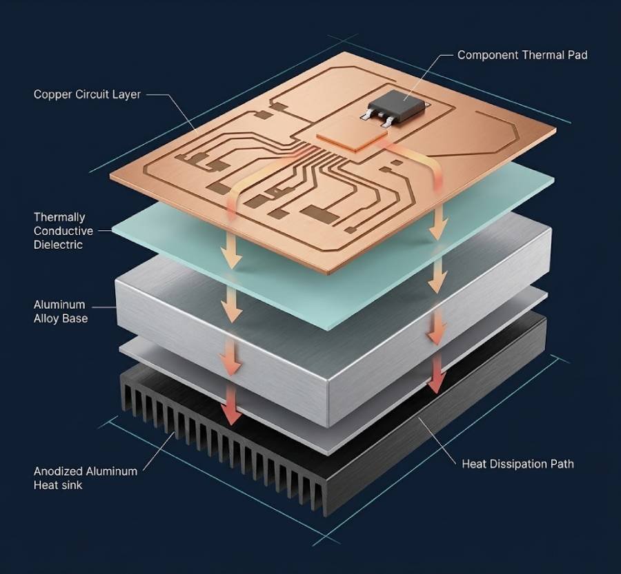
In a typical aluminum PCB stackup, heat generated by a power device first spreads through the copper circuit area, then passes through an electrically insulating dielectric layer before reaching the aluminum base. The aluminum base helps distribute heat toward a heat sink, chassis or other system-level cooling structure.
For this reason, material selection should not focus on aluminum thermal conductivity alone. Dielectric thickness, dielectric thermal conductivity, copper coverage, component footprint, aluminum thickness, thermal interface materials and mounting conditions all influence the final thermal result.
Need a standard multilayer material instead?
For designs where routing density, layer count and general-purpose electrical performance are the main priorities, review our
FR-4 PCB Material guide.
01
Copper Circuit Layer
Provides the conductive path for power and signals. Copper thickness, trace geometry and copper area affect current capacity and lateral heat spreading.
02
Thermally Conductive Dielectric
Provides electrical isolation between the circuit and aluminum base while transferring heat downward. Its thickness, thermal conductivity and dielectric strength are central selection variables.
03
Aluminum Alloy Base
Supplies mechanical support and heat spreading. Alloy family, thickness, temper and fabrication requirements should be selected according to the thermal and mechanical design.
04
System Thermal Interface
Connects the PCB to a heat sink, enclosure or cooling assembly. Flatness, fastening method, interface material and airflow can strongly affect real operating temperatures.
The aluminum base is an important part of the heat-spreading structure, but it is not a universal material. The next step is selecting an aluminum alloy family that fits the required balance of thermal conductivity, stiffness, corrosion resistance and machining performance.
ALUMINUM BASE SELECTION
Aluminum Base Alloy Options for PCB Materials
The aluminum base in an IMS PCB is normally selected from aluminum sheet or aluminum-alloy families rather than treated as one universal material. Common reference options include 1060, 5052 and 6061 aluminum, each offering a different balance of thermal conductivity, mechanical performance, corrosion resistance, formability and machinability.
HIGH-CONDUCTIVITY OPTION
1060 Aluminum
Often considered where high aluminum content, effective heat spreading and cost efficiency are important. It is commonly evaluated for LED lighting and power designs where the material does not need to carry significant mechanical loads.
Review: required stiffness, board thickness, hole pattern, CNC features and mechanical handling requirements.
BALANCED MECHANICAL OPTION
5052 Aluminum Alloy
Often evaluated when corrosion resistance, formability and mechanical durability require more attention than maximum base-metal thermal conductivity. It can be a practical option for designs involving mechanical handling, environmental exposure or formed features.
Review: alloy temper, bending or forming requirements, corrosion environment and material availability.
STRUCTURAL / MACHINABLE OPTION
6061 Aluminum Alloy
Often considered when rigidity, mounting stability and machining performance are important. It can be relevant for boards with demanding mechanical features, tighter structural requirements or more involved CNC processing.
Review: machining tolerances, mounting loads, fastening method, board geometry and thermal target.
PROJECT-SPECIFIED OPTION
Custom Aluminum Base
A defined alloy, temper or certified material may be specified where the application has customer-approved materials, documentation requirements, environmental constraints or long-term supply consistency requirements.
Review: customer drawing, material standard, CoC requirement, stackup, annual volume and engineering approval.
| Aluminum Base Option | Typical Reference Grade | Typical Thermal Conductivity* | Primary Strength | Best-Fit Design Considerations |
|---|---|---|---|---|
| High-conductivity aluminum | 1060-H18 | Approximately 203 W/m·K | Thermal spreading and cost efficiency | LED modules, power designs and structures with moderate mechanical demands |
| Balanced aluminum alloy | 5052-H34 | Approximately 150 W/m·K | Formability, corrosion resistance and mechanical balance | Projects involving formed features, mechanical handling or environmental exposure |
| Structural / machinable aluminum alloy | 6061-T6 | Approximately 150 W/m·K | Rigidity, machining and mounting performance | Mechanically demanding boards, CNC features and defined mounting structures |
| Project-specified aluminum | Per drawing or approved material specification | Verify by material datasheet | Application-specific compliance or performance requirements | Customer-controlled materials, CoC requirements, specialized environments or validated designs |
*Thermal-conductivity values are typical reference values for the listed alloy and temper, not finished-board or system-level thermal-performance guarantees. Confirm final values through the applicable material datasheet and stackup review.
Aluminum Alloy Is Only One Part of Thermal Performance
A higher-conductivity aluminum base cannot compensate for an unsuitable dielectric layer or incomplete system thermal path. In most insulated metal substrate designs, heat must first pass through the dielectric between the copper circuit and aluminum base. Final performance depends on dielectric thickness, dielectric thermal conductivity, copper area, component footprint, aluminum thickness, thermal interface materials, heat-sink design, mounting pressure and operating conditions.
Ready to turn a defined material stackup into a finished board?
Review our Aluminum PCB manufacturing capabilities for prototype, production and assembly support.
THERMAL INSULATION LAYER
The Dielectric Layer: The Primary Thermal Interface
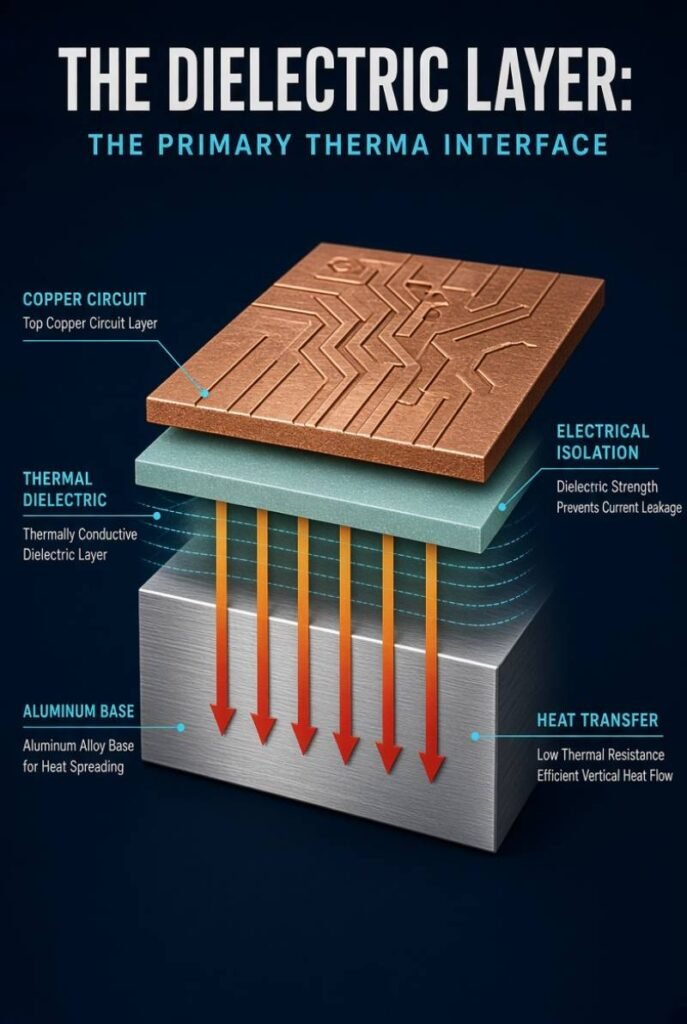
In an aluminum insulated metal substrate, the dielectric layer sits between the copper circuit and aluminum base. It must electrically isolate the circuit while allowing heat to move efficiently into the metal base. For this reason, dielectric selection often has a greater effect on through-thickness thermal resistance than the choice between common aluminum alloy grades.
Balance Heat Transfer With Electrical Isolation
A thermally conductive dielectric is not simply an adhesive layer. It is an engineered insulating material that must meet thermal, electrical and reliability requirements at the same time. Its thermal conductivity, thickness, dielectric strength, operating-temperature capability, adhesion and long-term stability should all be reviewed against the application.
In general, a thinner dielectric or a dielectric with higher thermal conductivity can reduce heat-transfer resistance. However, the thinnest available dielectric is not automatically the correct choice. It must still provide sufficient electrical insulation, breakdown-voltage margin and reliability for the operating voltage, temperature cycling and product environment.
Simplified dielectric thermal-resistance relationship
Rθ ≈ t / (k × A)
- Rθ = thermal resistance through the dielectric layer
- t = dielectric thickness
- k = dielectric thermal conductivity
- A = effective heat-transfer area
This relationship is a simplified engineering model. Actual board and system temperatures also depend on copper geometry, heat-source footprint, aluminum thickness, thermal interface materials, heat-sink design, mounting conditions and airflow.
How to Compare Thermally Conductive Dielectric Options
The categories below are planning references rather than universal material grades. Final dielectric selection should be based on the approved laminate datasheet, electrical requirements, required thickness, target thermal resistance and engineering review.
| Dielectric Selection Level | Typical Thermal Conductivity* | Typical Thickness Range* | Primary Design Priority | Engineering Review Focus |
|---|---|---|---|---|
| Standard thermal dielectric | Approximately 0.6–1.5 W/m·K | Approximately 75–200 μm | General thermal management with cost and insulation balance | Operating voltage, heat load, copper area, insulation margin and required board construction |
| Enhanced thermal dielectric | Approximately 1.5–3.0 W/m·K | Approximately 50–150 μm | Lower thermal resistance for higher power density | Dielectric reliability, thermal cycling, breakdown voltage, adhesion and assembly conditions |
| High-performance thermal dielectric | Approximately 3.0–8.0 W/m·K | Approximately 50–125 μm | Demanding thermal paths and tighter thermal budgets | Material data validation, electrical isolation, mechanical stress, cost, qualification and availability |
| Application-specific dielectric | Per approved material datasheet | Per stackup requirement | Defined compliance, reliability or customer-specified requirements | Material certification, dielectric strength, CTI, flammability, environmental exposure and long-term supply control |
*Typical planning ranges only. Thermal conductivity, dielectric thickness, thermal impedance and breakdown voltage vary by resin system, filler technology, test method, laminate construction and material supplier. Confirm all project values using the applicable material datasheet.
Specify Dielectric Performance, Not Only “High Thermal Conductivity”
A material request should define more than a W/m·K value. For a meaningful stackup review, specify the required dielectric thickness, operating voltage, isolation requirement, target thermal performance, component heat-source area, maximum operating temperature, expected thermal cycling and any compliance or material-documentation requirements.
Selecting the dielectric establishes the thermal and electrical foundation of the stackup. The next step is balancing that material choice with copper geometry, aluminum thickness, mechanical mounting and the full system heat-dissipation path.
SYSTEM-LEVEL MATERIAL SELECTION
How to Balance Thermal Performance, Insulation and Mechanical Requirements
An aluminum PCB should be selected as part of a complete thermal and mechanical system. The best material stackup is not necessarily the one with the highest dielectric conductivity or the thickest aluminum base. It is the stackup that satisfies thermal, electrical, mechanical, manufacturing and cost requirements together.
Review the Entire Heat-Dissipation Path
01
Heat Source
Power IC, LED or transistor
02
Copper Area
Pad, plane and heat spreading
03
Thermal Dielectric
Electrical isolation and heat transfer
04
Aluminum Base
Heat spreading and structural support
05
TIM / Heat Sink
Transfer to enclosure or ambient air
Copper Thickness and Copper Area
Copper must support required current while providing a low-resistance thermal-spreading path around heat-generating components. Increase copper area around thermal pads where practical, while maintaining electrical clearance and routing requirements.
Dielectric Thickness and Conductivity
Select the thinnest dielectric that still provides the required electrical isolation, breakdown-voltage margin and long-term reliability. Evaluate thickness and conductivity together instead of specifying either property alone.
Aluminum Alloy and Base Thickness
Choose the aluminum base according to heat spreading, stiffness, mounting method, board size, machining features and environmental requirements. A thicker base may improve rigidity and heat spreading, but it can also affect weight, machining and assembly design.
Thermal Interface and Heat Sink
Review the material and contact condition between the aluminum PCB and its heat sink or chassis. Thermal interface material, surface flatness, contact area and fastening pressure can determine whether the designed thermal path performs as expected.
Mechanical Mounting and Tolerance
Define mounting holes, screw locations, board flatness, connector loads, CNC features and enclosure interfaces early. Mechanical stress can affect both long-term reliability and the quality of the board-to-heat-sink contact.
Operating Environment and Validation
Consider ambient temperature, airflow, moisture, vibration, thermal cycling, operating duty cycle and safety requirements. Use simulation, prototype testing or both when the design has a tight thermal margin or a high reliability requirement.
Material Selection Matrix for Common Design Priorities
Scroll horizontally to view all four columns.
| Primary Design Priority | Material / Stackup Direction | Key Variables to Prioritize | Do Not Overlook |
|---|---|---|---|
| Cost-efficient LED thermal management | Aluminum IMS with a standard or enhanced thermal dielectric | Heat-source footprint, copper pad area, dielectric thickness, aluminum thickness and heat-sink interface | Electrical isolation margin, enclosure temperature and mounting-flatness control |
| Higher power density or tighter thermal budget | Enhanced or high-performance dielectric with stackup-specific thermal review | Lower dielectric thermal resistance, copper spreading area, heat-sink capacity and thermal-interface quality | Breakdown voltage, thermal cycling, dielectric reliability and prototype validation |
| Mechanical strength, corrosion resistance or formed features | Evaluate balanced aluminum-alloy options such as 5052-class material | Alloy temper, board thickness, forming needs, corrosion environment and mounting loads | Tradeoff between mechanical properties, thermal conductivity and material availability |
| Rigidity, CNC features or demanding mounting structure | Evaluate structural / machinable alloy options such as 6061-class material | Machining tolerance, fastening geometry, board flatness, enclosure interface and mechanical load | Finished-board thermal path and whether a different material system may better fit the design |
| High-density multilayer routing or complex interconnect | Evaluate FR-4, high-Tg or hybrid stackup options before selecting standard aluminum IMS | Layer count, impedance, via structure, routing density, power dissipation and localized cooling approach | Whether aluminum IMS construction introduces unnecessary routing or manufacturing constraints |
| Extreme thermal, electrical insulation or high-reliability requirements | Evaluate copper-core, ceramic or application-specific thermal substrate solutions | Heat flux, isolation level, operating temperature, power cycling, reliability target and qualification plan | Cost, brittleness, weight, supply chain and full system-level validation |
This matrix is a preliminary material-selection framework, not a substitute for application-specific engineering review. Final stackup selection should be confirmed against electrical, thermal, mechanical, reliability and manufacturing requirements.
Material Selection Guide
Compare Other PCB Material Paths
Aluminum IMS is a strong choice for many thermal-management applications, but the optimal substrate depends on your primary design constraint—whether it is multilayer routing, higher heat spreading, electrical isolation or low-loss signal performance.
FR-4 PCB Material
Choose FR-4 when flexible multilayer routing, conventional PCB construction, dense interconnects and broad material availability are the main priorities.
Explore FR-4 Material →Copper Core PCB Material
Evaluate copper-core solutions when your design requires stronger heat spreading or must manage a higher thermal load than a standard aluminum-base system.
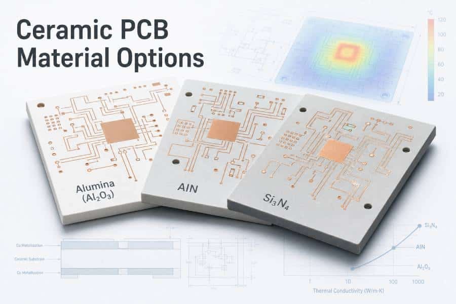
Explore Copper Core Material →Ceramic PCB Materials
Consider ceramic substrates for demanding thermal performance, high electrical isolation, elevated operating temperatures or specialized reliability requirements.
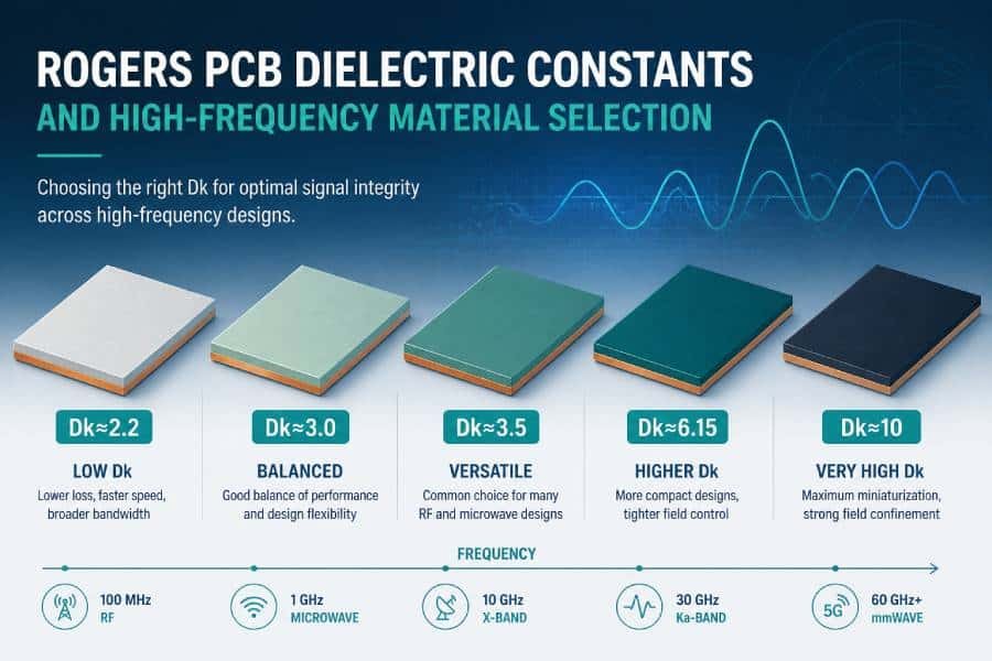
Explore Ceramic Materials →RF / High Frequency Materials
Use dedicated RF and high-frequency laminates when low loss, stable dielectric properties and controlled impedance are more important than metal-base heat spreading.
Explore RF Materials →Pre-Fabrication Check
Before You Finalize an Aluminum PCB Material Stackup
Review the complete thermal, electrical and mechanical path before releasing an aluminum IMS design for fabrication. A well-defined stackup helps reduce material risk, improve manufacturability and support more reliable thermal performance in the final assembly.
- Identify every primary heat source and its maximum power dissipation under worst-case operating conditions.
- Define the temperature target for the component case, junction or surrounding assembly environment.
- Specify dielectric conductivity and thickness together rather than selecting a W/m·K value alone.
- Verify electrical isolation requirements, including operating voltage, dielectric strength and safety margin.
- Confirm copper thickness and copper area for current carrying, thermal spreading and pad-level heat transfer.
- Select the aluminum base material and thickness based on heat spreading, rigidity, machining and mounting needs.
- Define the heat-sink or chassis interface, including TIM, contact area, mounting pressure and surface flatness.
- Review mechanical details early, including mounting holes, screw locations, board flatness and CNC features.
- Account for operating conditions, such as ambient temperature, airflow, vibration, moisture and thermal cycling.
- Plan validation for tight thermal margins, using simulation, prototype testing or both before volume production.
Next Step
Have Your Material Requirements and Thermal Path Defined?
Move from stackup selection to manufacturability review. Share your PCB files, material requirements and thermal-design details to evaluate prototype, production and assembly options for your aluminum PCB project.
Prototype, production and assembly support
FROM MATERIAL SELECTION TO FABRICATION
How to Specify Aluminum PCB Material for Quotation
A complete aluminum PCB quotation requires more than Gerber files and board dimensions. Thermal, dielectric, mechanical and assembly requirements should be defined early so the proposed material system supports the actual operating conditions—not only the basic circuit layout.
What to Send for an Initial Review
- PCB design data
Gerber, ODB++, IPC-2581 or equivalent fabrication data, together with the board outline and fabrication drawing where available. - Required board construction
Single-sided, double-sided, multilayer or hybrid construction, including the required finished board thickness. - Copper requirements
Copper weight, current-carrying requirements, minimum trace and spacing, thermal-pad geometry and copper-area priorities. - Dielectric requirements
Preferred dielectric thickness, thermal-conductivity target, operating voltage, isolation requirement and any dielectric-strength requirement. - Aluminum base requirements
Preferred alloy family or approved material specification, base thickness, mechanical constraints, machining features and corrosion-related requirements. - Thermal design information
Primary heat sources, maximum power dissipation, allowable operating temperature, ambient condition, cooling method and heat-sink or chassis interface. - Assembly and finish requirements
Surface finish, solder-mask requirements, component assembly process, thermal pad or insulated-mounting requirements and panelization preference. - Quality and documentation requirements
Required inspection level, test requirements, material documentation, CoC, first article, RoHS/REACH, UL or customer-specific compliance requirements.
ENGINEERING REVIEW PRIORITIES
Define These Before Finalizing the Stackup
Define whether the goal is lower component temperature, higher allowable power, longer lifetime, reduced heat-sink size or a combination of these objectives.
Specify working voltage, test voltage, creepage, clearance and any application-specific isolation requirement before choosing dielectric thickness.
Clarify how the board attaches to the heat sink, housing or chassis, including screw locations, pressure points, flatness and thermal interface material.
For designs with narrow thermal margins, include simulation targets, test points, prototype quantity and the required validation method.
| Specification Area | Information to Provide | Why It Matters | If Unknown |
|---|---|---|---|
| PCB construction | Layer count, finished thickness, board outline, routing or CNC features | Determines feasible IMS construction, base thickness, mechanical processing and fabrication route | Provide the application, board dimensions and available drawing for an initial engineering recommendation |
| Copper system | Copper weight, current, trace geometry, thermal-pad size and copper-area requirement | Influences current capacity, lateral heat spreading, etching capability and stackup selection | Provide component current, power map and the existing layout where available |
| Dielectric layer | Thermal-conductivity target, thickness, operating voltage, isolation and dielectric-strength requirement | Controls the balance between heat transfer, electrical insulation and reliability | Provide working voltage, power dissipation, temperature target and safety requirement |
| Aluminum base | Preferred alloy, temper if controlled, base thickness, flatness and mechanical requirements | Affects heat spreading, stiffness, machining, corrosion behavior and mounting compatibility | Define mounting method, board size, environmental conditions and expected mechanical loads |
| Thermal interface | Heat-sink design, TIM type, contact area, mounting screws or clips and cooling method | The board-to-heat-sink interface can dominate system-level thermal performance | Share enclosure drawings, heat-sink details or the intended cooling approach |
| Quality and compliance | Testing, inspection, material documents, reporting and regulatory requirements | Ensures the material system, fabrication route and quality plan match project requirements | Identify the end market, customer standard and required certifications or reports |
A preliminary quotation can begin with incomplete information, but final material selection should be confirmed after thermal, electrical, mechanical and manufacturing requirements are reviewed together.
Ready for Fabrication?
Ready to Move From Material Selection to Fabrication?
Share your PCB files, target stackup, thermal requirements and quality documentation needs. Our engineering team can review material feasibility and support your aluminum PCB from prototype through production and assembly.
Aluminum PCB prototype, production and assembly
MATERIAL SELECTION BOUNDARIES
When Aluminum PCB Material Is Not the Right Choice
Aluminum IMS material is highly effective for many thermal-management designs, but it is not a universal replacement for every PCB substrate. The correct choice depends on routing density, layer count, power density, insulation level, mechanical constraints, operating environment and electrical performance requirements.
Choose FR-4 for Flexible Multilayer Routing
Standard or high-Tg FR-4 material is often the better starting point when the design needs multiple signal layers, dense routing, blind or buried vias, controlled impedance or a broad range of conventional PCB constructions. Local thermal measures can be added without changing the entire substrate to aluminum IMS.
Explore FR-4 PCB Material →Evaluate Copper Core for Higher Heat-Spreading Demand
When the thermal load or local heat flux exceeds the practical capability of an aluminum-based system, a copper-core or copper-based IMS construction may be evaluated. Copper can offer stronger heat spreading, but it also introduces cost, weight, process and mechanical tradeoffs.
03
Evaluate Ceramic for Extreme Thermal or Isolation Requirements
Ceramic substrates may be more appropriate where high operating temperature, demanding electrical isolation, high reliability or extreme thermal performance is required. Material options such as alumina and aluminum nitride have distinct thermal, electrical, cost and mechanical tradeoffs.
04
Choose RF Materials for Low-Loss Signal Performance
For RF, microwave or high-speed digital applications, dielectric constant, loss tangent, impedance stability and frequency response may be more important than metal-base heat spreading. A dedicated RF or high-frequency laminate should be evaluated first.
| When Your Main Requirement Is | Start by Evaluating | Why It May Fit | Key Tradeoff to Review |
|---|---|---|---|
| LED, power modules or moderate-to-high thermal loading with a direct heat-sink path | Aluminum PCB Material | Combines circuit routing, electrical insulation, structural support and heat transfer to a metal base | Dielectric thermal resistance, electrical isolation, routing flexibility and heat-sink interface quality |
| Complex multilayer routing, dense interconnect, controlled impedance or conventional PCB construction | FR-4 PCB Material | Offers broad multilayer, routing and fabrication flexibility | Requires dedicated thermal design measures when heat dissipation becomes significant |
| Higher heat flux or stronger lateral heat spreading than aluminum can provide | Copper Core PCB Material | Copper-based systems can improve heat spreading in demanding thermal designs | Weight, cost, fabrication complexity and system-level mechanical implications |
| High isolation, high temperature, power cycling or extreme thermal-performance requirement | Ceramic PCB Materials | Ceramic substrates can provide strong electrical insulation and thermal performance in specialized applications | Cost, brittleness, substrate format, assembly method and supply-chain requirements |
| RF, microwave or high-speed signal integrity with low dielectric loss | RF / High Frequency PCB Materials | Optimized dielectric properties support impedance control and low-loss electrical performance | Thermal management must be evaluated separately from high-frequency material requirements |
Engineering Selection Principle
Choose the Material System That Solves the Actual Constraint
Aluminum PCB material is a strong choice when an electrically insulated path from copper circuitry to a metal heat-spreading base supports the product’s thermal and mechanical requirements. However, the best material is not always the one with the highest thermal conductivity. Select the substrate that addresses the design’s primary constraint—whether that is routing density, low signal loss, extreme heat flux, electrical isolation, mechanical strength or long-term environmental reliability.
- Thermal performance
- Electrical isolation
- Routing density
- Signal integrity
- Mechanical requirements
- Reliability conditions
ALUMINUM PCB MATERIAL FAQ
Frequently Asked Questions About Aluminum PCB Material
These answers address common material-selection questions for aluminum insulated metal substrate and metal-core PCB designs. Final specifications should always be confirmed against the approved material datasheet, stackup and application requirements.
Aluminum PCB material is an insulated metal substrate system that typically combines a copper circuit layer, a thermally conductive dielectric layer and an aluminum base. The dielectric electrically isolates the circuit from the metal base while transferring heat toward the aluminum layer and the system cooling structure.
Aluminum PCB bases may use aluminum sheet or alloy families such as 1060, 5052 or 6061, depending on the required balance of thermal conductivity, mechanical strength, corrosion resistance, formability and machining performance. The final alloy and temper should be confirmed through the approved material stackup and engineering review.
No. The aluminum base helps spread heat, but heat must first pass from the copper circuit through the electrically insulating dielectric layer. Dielectric thickness, dielectric thermal conductivity, copper area, component footprint, thermal interface material, heat-sink design and mounting conditions can all strongly affect the final thermal result.
Choose dielectric thickness by balancing thermal resistance with electrical isolation and reliability. A thinner dielectric can reduce thermal resistance, but it must still meet working-voltage, dielectric-strength, safety, thermal-cycling and application-environment requirements. Review thickness together with dielectric thermal conductivity rather than selecting either value alone.
Aluminum PCB material is commonly used for LED modules because it can provide a direct heat-transfer path from the copper circuit through a thermally conductive dielectric to an aluminum base and heat sink. Suitability still depends on LED power density, thermal-pad area, dielectric selection, mounting method, ambient temperature and cooling design.
Multilayer or hybrid aluminum PCB constructions are possible in selected designs, but standard aluminum IMS is most commonly used where the circuit and heat path can be managed with a simpler construction. When the design requires dense multilayer routing, complex via structures or controlled impedance, FR-4, high-Tg or hybrid stackup options may be more suitable.
Choose aluminum PCB material when the design benefits from an electrically insulated path to a metal heat-spreading base, such as LED lighting, power modules or thermally demanding industrial electronics. Choose FR-4 when multilayer routing flexibility, high interconnect density, conventional PCB construction or broad material availability is the primary requirement.
Provide PCB data, finished thickness, copper requirements, dielectric thermal and electrical targets, aluminum-base requirements, operating voltage, heat-source information, cooling approach, mounting details, surface finish, quantity and required quality documentation. If some values are not yet defined, provide the application conditions so an initial material review can be performed.
Not necessarily. An aluminum PCB can spread heat and transfer it toward a mechanical cooling structure, but whether it eliminates the need for a separate heat sink depends on total power dissipation, component temperature limit, board area, enclosure design, airflow and ambient conditions. Evaluate the complete thermal path before removing a heat sink from the design.
Aluminum PCB usually refers to a metal-core PCB using an aluminum base. IMS means insulated metal substrate and emphasizes the electrically insulating, thermally conductive layer between the circuit and metal base. MCPCB is the broader term for metal-core PCB constructions, which may use aluminum, copper or other metal-base materials.
Ready for the Next Step?
Turn Your Material Requirements Into a Manufacturable Aluminum PCB
Share your PCB data, thermal requirements and target material stackup for an engineering-oriented review. Once the material system is defined, our aluminum PCB manufacturing team can support prototype, production and assembly planning for your project.
Prototype, production and assembly support for aluminum PCB projects