High-Thermal-Conductivity PCB Substrate Guide
Copper Core PCB Material for High-Power Thermal Management
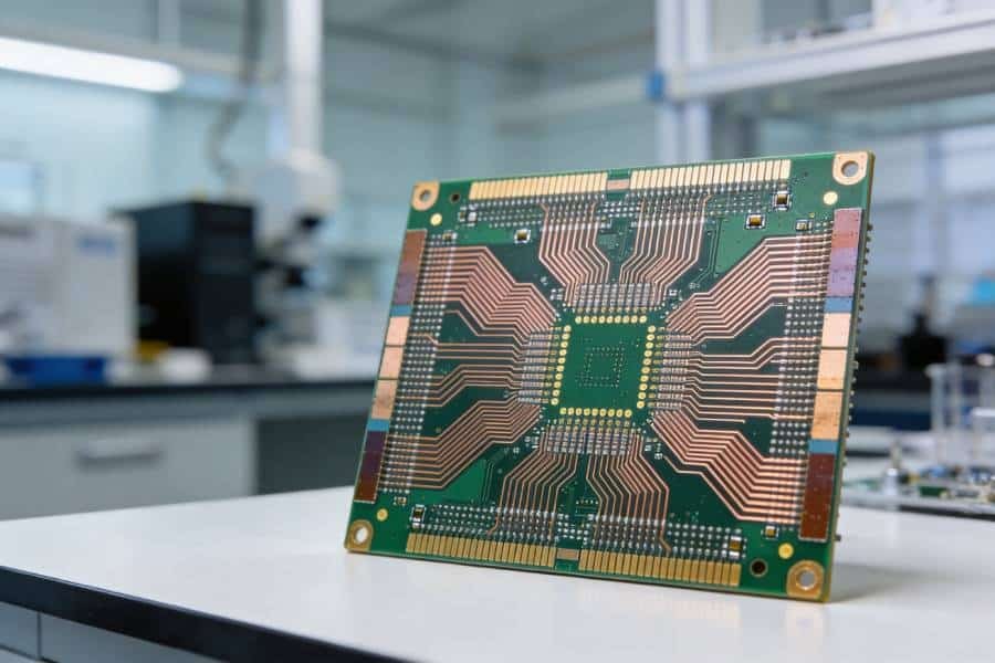
Copper core PCB material is designed for electronic assemblies that must move heat away from concentrated hot spots quickly and reliably. By combining an electrically insulating dielectric layer with a highly conductive copper base, this material system supports efficient heat spreading in compact, high-power and thermally demanding designs.
This guide explains how copper core PCB materials work, how they compare with aluminum core and FR-4 constructions, and what engineers should evaluate before defining a manufacturable thermal stackup.
- High thermal spreading capacity
- Electrical isolation through engineered dielectric systems
- Designed for demanding power-density applications
What Is Copper Core PCB Material?
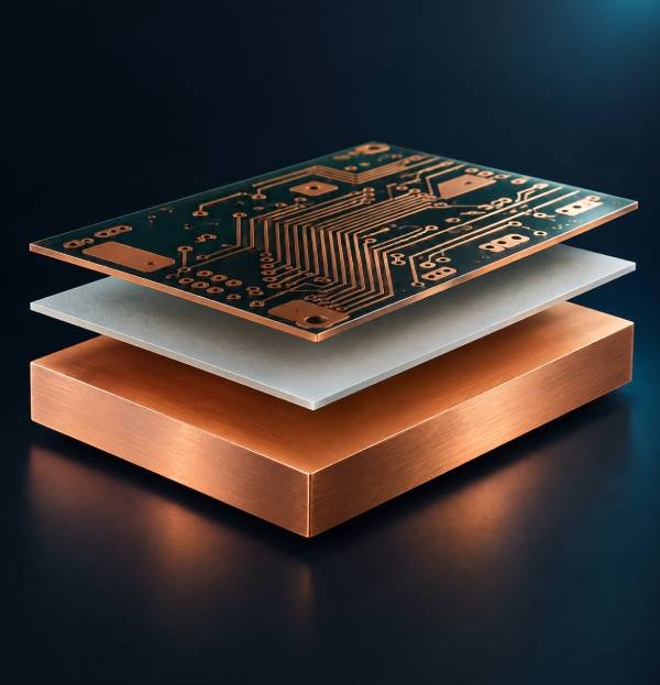
Copper core PCB material is a thermal-management substrate system that uses copper as a central heat-spreading layer, base plate or structural core. In a typical insulated metal substrate construction, the copper core sits beneath an electrically insulating dielectric layer and the patterned copper circuit layer.
When heat is generated by power semiconductors, LEDs, RF devices or other heat-intensive components, it moves from the component package into the circuit layer, through the dielectric layer and into the copper core. The copper base then spreads that heat laterally across a much larger area, helping transfer it to a heat sink, housing, chassis, airflow path or other external cooling structure.
Copper is selected when the design needs stronger thermal spreading than a conventional FR-4 board or an aluminum-core construction can reasonably provide. It is particularly useful when high thermal density is concentrated in a limited board area and the system must maintain acceptable operating temperatures over time.
A Material System, Not Just a Copper Plate
The copper base is important, but it does not determine the complete thermal performance of the finished board by itself. The dielectric material, dielectric thickness, circuit copper geometry, component footprint, mounting interface, thermal interface material and external cooling method all contribute to the final thermal resistance of the assembly.
For this reason, copper core PCB material should be selected as part of a complete thermal path rather than as a standalone solution for every overheating problem.
How a Copper Core PCB Transfers Heat
A copper core PCB is designed to create a controlled path for heat to leave high-power components. The objective is not simply to use a more conductive metal. The objective is to reduce resistance across the entire route from the heat source to the surrounding cooling system.
Heat enters the circuit area
Heat begins at a power transistor, LED, RF device, driver IC or other heat-generating component. Pad design, copper area and component placement influence how efficiently heat enters the board.
Heat crosses the dielectric layer
The dielectric layer provides electrical isolation between the circuit and the copper base. Its thickness and thermal conductivity strongly influence through-thickness thermal resistance.
The copper core spreads heat
The copper core distributes heat laterally across a larger surface area, reducing localized thermal concentration beneath the component.
Heat leaves through the mechanical interface
The board must transfer heat into a heat sink, chassis, enclosure, airflow path or liquid-cooling system. Interface flatness, fastening pressure and thermal interface material can affect the final result.
Think in Terms of the Complete Thermal Path
A copper base can improve heat spreading, but it cannot compensate for an unsuitable dielectric, poor component placement, inadequate heat-sink contact or insufficient system cooling. The most reliable thermal designs evaluate each stage of the heat path before the stackup is finalized.
Typical Copper Core PCB Material Structures
Copper core constructions vary according to thermal load, insulation requirements, circuit density, current capacity, mounting method and cost target. The following structures illustrate common material paths that may be evaluated during engineering review.
Swipe horizontally to compare all material structure options.
| Structure Type | Typical Material Path | Primary Design Value | Common Evaluation Factors |
|---|---|---|---|
| Single-Sided Copper Core PCB | Patterned circuit copper + thermally conductive dielectric + copper base | Efficient heat spreading for component layouts concentrated on one circuit side | Power dissipation, dielectric isolation, copper base thickness, mounting interface and heat-sink contact |
| Double-Sided Copper Core Construction | Insulated circuit structures arranged around a copper core or copper heat-spreading layer | More compact thermal design where circuitry must be distributed across both sides | Layer-to-core insulation, interconnection strategy, drilling, routing, assembly sequence and thermal balance |
| Copper Base Plate PCB | Rigid circuit stackup integrated with a copper base plate or dedicated heat-spreading element | Mechanical support and thermal spreading for higher-power assemblies | Base-plate geometry, flatness, fastening locations, thermal interface requirements and machining features |
| Heavy Copper with Copper Core | Higher-weight circuit copper combined with a copper heat-spreading base or core | Supports both high-current routing and demanding thermal conditions | Trace geometry, current load, copper balance, etching compensation, solderability and thermal mass during assembly |
| Localized Copper Heat-Spreading Design | Standard circuit material combined with copper inserts, copper-backed zones or dedicated heat-spreading regions | Targets one or more localized hot spots without using a full copper-core construction | Insert location, bonding method, planarity, CTE interaction, cost and manufacturability review |
Not every structure is appropriate for every project. The most suitable option depends on the required thermal path, working voltage, electrical isolation, layer count, component density, mechanical constraints, target volume and total cost of ownership.
Copper Core vs Aluminum Core vs FR-4 PCB Materials
Material selection should begin with the actual engineering constraint rather than with a general preference for the highest-conductivity metal. Copper core, aluminum core and FR-4 each solve different combinations of thermal, electrical, mechanical and cost requirements.
Swipe horizontally to compare material options.
| Selection Factor | Copper Core PCB Material | Aluminum Core PCB Material | Standard FR-4 PCB Material |
|---|---|---|---|
| Heat-Spreading Potential | Excellent lateral heat spreading when the copper base is integrated into an effective thermal path | Strong thermal performance for many LED, power and general metal-core applications | Limited intrinsic thermal conduction; commonly enhanced with copper planes, thermal vias and external cooling features |
| Metal Base Conductivity | Copper metal is approximately 380–400 W/m·K | Aluminum alloys commonly used in thermal applications are approximately 150–235 W/m·K | FR-4 laminate is typically around 0.3 W/m·K and is not a metal heat-spreading base |
| Weight | Higher; should be evaluated where board mass, mounting load or vibration matters | Lower than copper while still providing a metal thermal path | Low; often beneficial for lightweight and complex multilayer designs |
| Relative Material and Processing Cost | Higher due to copper material, machining and construction complexity | Moderate; often a cost-effective metal-core option | Generally lower for standard constructions, although advanced multilayer stackups can increase cost |
| High-Current Compatibility | Strong when circuit copper, trace geometry and heat path are engineered for the current load | Suitable for many power designs; verify conductor sizing and thermal requirements | Depends primarily on copper weight, trace geometry, layer count and thermal design |
| Mechanical and Machining Considerations | Rigid and durable, but more demanding to route, drill and machine | Rigid with comparatively easier processing than copper in many applications | Well suited to complex routing and multilayer interconnection structures |
| Best-Fit Design Direction | High-power-density designs where maximum heat spreading justifies added weight and cost | Thermally demanding designs that need a practical balance of performance, weight and cost | Signal, control and multilayer applications where thermal loads are moderate or managed through other design features |
Choose copper core material when thermal density is high, heat must spread quickly from localized devices, and the additional material and manufacturing complexity is justified by system reliability or power-performance requirements. Choose aluminum core material when strong thermal performance is needed with a more economical and lighter metal substrate. Choose FR-4 when routing flexibility, multilayer density, signal integrity or cost efficiency is the dominant design requirement.
For applications where a lighter and more cost-efficient metal substrate may be sufficient, explore our Aluminum PCB Material guide.
For standard multilayer and signal-focused constructions, see our FR-4 PCB Material guide.
Key Copper Core PCB Material Properties to Evaluate
A copper core is only one part of the material system. Engineers should evaluate a copper-based thermal stackup against the electrical, mechanical and assembly conditions of the finished product rather than specifying a copper base solely by thickness or thermal conductivity.
Thermal Conductivity and Thermal Resistance
Copper provides a highly conductive path for lateral heat spreading. However, the dielectric layer between the circuit and the copper core often has a major influence on through-thickness thermal resistance. A thinner or more thermally conductive dielectric may improve heat transfer, but it must still meet the required electrical isolation and reliability conditions.
Electrical Isolation
The dielectric system must withstand the design voltage, expected transients, operating temperature and environmental conditions. The required isolation level should be defined before optimizing solely for thermal transfer, especially in power conversion, automotive, industrial and high-voltage applications.
Mechanical Stability and Weight
Copper provides a rigid and durable base, but it also adds mass. Board weight, mounting location, vibration exposure, connector loading, enclosure design and heat-sink attachment method should be reviewed early in the design process.
Manufacturing and Assembly Compatibility
Copper-core constructions can introduce higher thermal mass and more demanding machining requirements than conventional FR-4 boards. Routing, drilling, slotting, profile tolerances, panel design, soldering profile and assembly sequence should be reviewed through DFM before production.
The Dielectric Layer: Thermal Transfer and Electrical Isolation
In many copper core PCB constructions, the dielectric layer is the most important balancing element between thermal performance and electrical safety. It must move heat toward the copper base while electrically isolating the circuit from that conductive metal layer.
A dielectric that is too thick or thermally resistive can limit heat transfer even when the copper base is highly conductive. A dielectric selected only for low thermal resistance may not provide enough voltage withstand capability, long-term reliability or mechanical robustness for the intended application. The correct choice depends on the complete operating environment.
Questions to Define Before Selecting the Dielectric System
- What power dissipation and peak thermal load will the board experience?
- What working voltage, isolation voltage and transient conditions must the dielectric withstand?
- What operating temperature range, humidity exposure and thermal cycling conditions apply?
- How much heat must move through the board versus spread laterally across the copper base?
- Will the board attach directly to a heat sink, chassis or thermal interface material?
- What assembly process and reflow temperature profile will the finished board experience?
Material-Level Conductivity Is Not the Final Thermal Result
The final operating temperature of a component depends on the entire system: junction-to-case resistance, pad design, circuit copper, dielectric layer, copper core, interface material, mounting pressure, heat-sink performance and ambient cooling conditions. A material review should therefore use the complete thermal path, not a single conductivity value.
Copper Core PCB vs Heavy Copper PCB vs DBC
Several PCB and power-electronics terms use the word “copper,” but they describe different material systems and should not be treated as interchangeable. Identifying the correct construction early helps prevent inaccurate specifications, unsuitable quotations and unnecessary redesign work.
Swipe horizontally to compare technical terms.
| Term | What It Describes | Key Selection Distinction |
|---|---|---|
| Copper Core PCB | A PCB construction using a copper base plate, copper core or dedicated copper heat-spreading structure. | The primary purpose is thermal spreading and, in some constructions, mechanical support. Electrical isolation is typically provided by a dielectric system between the circuit and copper base. |
| Heavy Copper PCB | A PCB with higher-weight conductor copper used on one or more circuit layers. | The primary purpose is higher current capacity, lower conductor resistance and improved durability of power paths. It may use FR-4, metal-core or other substrate systems. |
| Copper-Clad Laminate | A laminate material with copper foil bonded to an insulating substrate. | This is a broad material category and does not automatically mean the PCB contains a copper core or dedicated metal heat-spreading base. |
| DBC / Direct Bonded Copper | A high-performance construction in which copper is directly bonded to a ceramic substrate. | Commonly evaluated for demanding power-module applications requiring strong electrical isolation, thermal performance and reliability; it is a different material system from a typical insulated copper-core PCB. |
| Copper Heat Sink PCB | A PCB incorporating copper-backed zones, copper inserts or heat-spreading elements. | The design may use localized copper thermal features rather than a full copper-core construction across the entire board. |
How to Balance Thermal, Electrical and Mechanical Requirements
The highest-conductivity base material is not automatically the best stackup. A practical copper core PCB design balances heat transfer with electrical isolation, mechanical integration, current capacity, manufacturability, assembly yield and total project cost.
Start With the Actual Constraint
First identify the problem the material system must solve. If localized hot spots are driving component temperature, copper core material may be appropriate. If the design needs high current but thermal density is moderate, heavy copper on FR-4 or another substrate may be more suitable. If high isolation and extreme power-module conditions dominate, a ceramic-based approach may need to be evaluated.
Define the Entire Cooling Strategy
Document the heat source, target operating temperature, mounting surface, heat-sink interface, airflow conditions and enclosure restrictions. This information gives engineering teams the context needed to assess whether copper core material creates a meaningful system-level improvement.
Review Manufacturability Before Finalizing the Stackup
Early DFM review helps confirm that drilling, routing, slots, cutouts, panelization, copper balance, planarity and assembly conditions are compatible with the proposed copper-core construction. Reviewing these requirements before prototype release can reduce avoidable revisions, yield risks and lead-time delays.
Next Step: Engineering Review
Have Your Thermal Path and Material Requirements Defined?
Turn your power dissipation, isolation requirements, cooling method and mechanical constraints into a practical copper core PCB stackup. An early engineering review can help confirm the dielectric system, copper-base construction and manufacturing path before prototype release.
Material, stackup and manufacturability guidance
How to Specify Copper Core PCB Material for Quotation
A complete material specification helps reduce back-and-forth during quotation and gives the engineering team enough information to evaluate a manufacturable copper-core construction. If every material parameter is not yet defined, provide the thermal and electrical design targets so the stackup can be reviewed with the correct context.
Information to Include in Your RFQ
- Gerber files, drill files and board outline
- Target quantity, prototype or production stage, and expected annual volume
- Board dimensions, layer count and preferred construction if known
- Circuit copper weight and high-current routing requirements
- Preferred copper core or copper base thickness, if already specified
- Power dissipation, peak thermal load and critical component locations
- Working voltage, isolation requirement and environmental conditions
- Surface finish, solder mask, legend, panelization and mechanical features
- Mounting method, heat-sink interface and thermal interface material details
- Assembly requirement, component list and special reliability expectations
Quote a Thermal Stackup With the System Context
For the most useful engineering feedback, include a short description of where heat enters the board and how it is expected to leave the assembly. A copper core may spread heat effectively, but the intended heat-sink, chassis or enclosure interface determines whether that thermal benefit can be fully used in the final product.
Ready for Fabrication?
Have Your Copper Core PCB Requirements Ready for Quotation?
When your design files, thermal requirements and mechanical details are defined, our manufacturing team can review the proposed construction and support your copper core PCB prototype, production or assembly project.
Prototype, production and assembly support
When Copper Core PCB Material Is Not the Right Choice
Copper core PCB material is not a universal replacement for aluminum core or FR-4. Its higher thermal performance may not justify the added cost, mass and machining complexity when the system’s real constraint lies elsewhere.
- Choose aluminum core material when the design requires good metal-based thermal performance with lower material cost and lower weight.
- Choose FR-4 when complex multilayer routing, fine-pitch interconnection, signal integrity or cost efficiency is more important than direct metal-based heat spreading.
- Choose a heavy copper construction when the primary issue is current carrying capacity rather than heat transfer through a metal core.
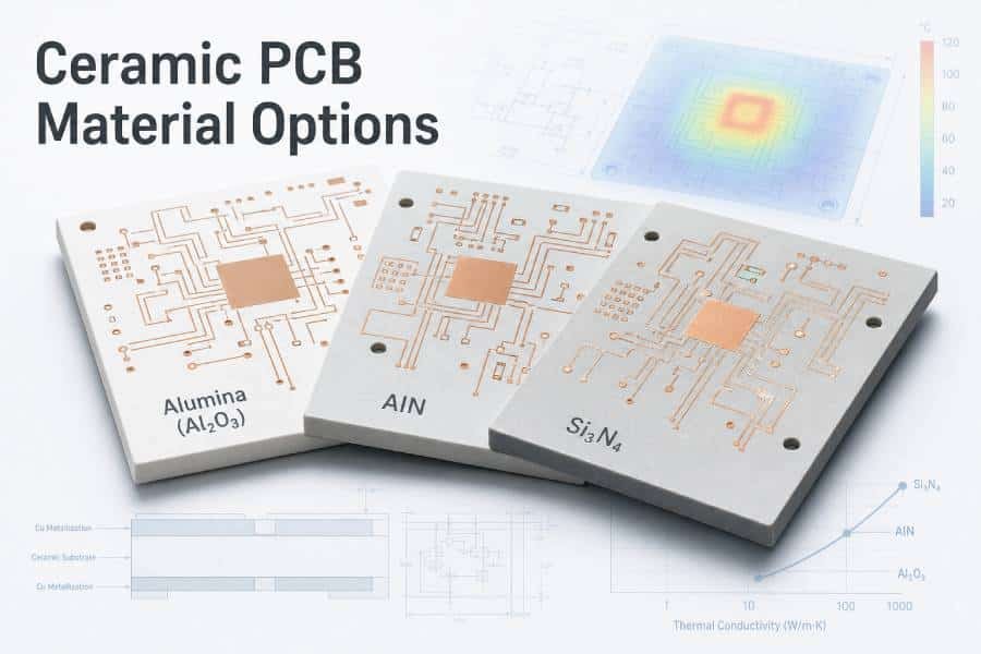
- Evaluate ceramic or DBC-based materials when the application requires a specialized combination of power-module thermal performance, electrical isolation and long-term reliability.
- Improve the heat sink, mounting pressure, thermal interface material or airflow system when the bottleneck exists outside the PCB itself.
Choose the Material System That Solves the Actual Constraint
The right material is the one that addresses the dominant engineering limitation without adding unnecessary cost or complexity. Copper core PCB material is most valuable when heat spreading is genuinely the limiting factor and the surrounding mechanical and cooling system can make effective use of the copper thermal path.
Material Selection Paths
Compare Other PCB Material Paths
If copper core material is not the most practical solution for your design, compare the material system that best addresses your dominant thermal, electrical, current-carrying or reliability constraint.
Aluminum PCB Material
A practical metal-core option for applications that need efficient thermal management with lower weight and a more cost-conscious material path.
Explore Aluminum Material →FR-4 PCB Material
A versatile material path for standard multilayer, signal, control and routing-intensive designs where direct metal-based heat spreading is not the primary requirement.
Explore FR-4 Material →Heavy Copper PCB
A suitable direction when high current capacity, lower conductor resistance and robust power routing are the main constraints rather than heat transfer through a metal core.
Explore Heavy Copper PCB →Ceramic PCB Materials
A specialized path for demanding power-electronics applications that require a high-performance combination of electrical isolation, thermal control and long-term reliability.
Explore Ceramic Materials →Frequently Asked Questions About Copper Core PCB Material
Copper core PCB material is a thermal-management PCB construction that uses a copper base, copper core or copper heat-spreading structure beneath insulated circuit layers. It is selected to move heat away from high-power components more effectively than conventional PCB substrates.
Copper generally provides stronger thermal spreading than aluminum, but it also increases material cost, board weight and machining complexity. Copper core material is typically selected when higher heat density or critical hot spots justify those tradeoffs. Aluminum core material is often the more balanced choice for many thermal-management applications.
Copper metal itself is commonly around 380–400 W/m·K. However, that figure should not be treated as the thermal conductivity of the complete PCB. The actual board-level thermal performance depends on the dielectric layer, circuit structure, component interface, mounting method and external cooling system.
A copper core PCB uses a copper base or core mainly for heat spreading and structural support. A heavy copper PCB uses thicker circuit conductors mainly to carry higher current and reduce electrical resistance. A project can combine both features, but they describe different design purposes.
Yes. Copper core constructions can support high-current applications when conductor weight, trace width, copper geometry, dielectric performance, thermal path and assembly requirements are designed as a complete system.
Provide design files, board dimensions, quantity, layer count, circuit copper requirements, thermal load, insulation requirements, desired surface finish, mechanical features, mounting details and any assembly requirements. If the copper core and dielectric system are not yet defined, include the operating conditions so they can be reviewed during stackup evaluation.
Engineering Review & Manufacturing Support
Turn Your Thermal Requirements Into a Manufacturable Copper Core PCB
Share your thermal targets, electrical isolation requirements, mechanical constraints and design files. Our engineering team can help evaluate a copper core PCB material system that aligns heat spreading, manufacturability, assembly conditions and your intended production requirements.
- Material and dielectric stackup review
- Thermal-path and manufacturability evaluation
- Prototype, production and assembly support
From thermal stackup review to copper core PCB fabrication, assembly and production support.