Table of Contents
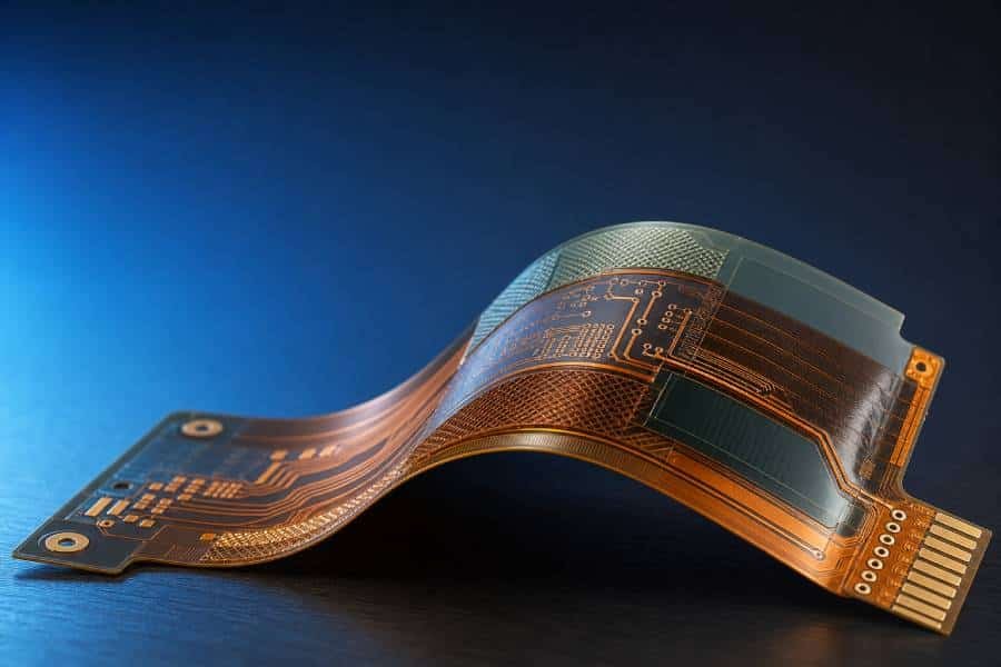
Flexible PCBs are built from a combination of flexible substrates, copper conductors, coverlay, and adhesives, and each layer affects how the circuit performs in real-world use.
Among these materials, polyimide is the most common base film because it offers strong thermal stability, good mechanical durability, and reliable performance in demanding flex applications, while PET and other options may suit lower-cost or less demanding designs.
Choosing the right flexible PCB material is not just a technical detail—it directly impacts bend life, assembly reliability, temperature resistance, and overall manufacturing cost.
In this guide, we will compare the main flexible PCB materials, explain where PI and PET fit best, and help you choose the right stackup for your application.
What Are Flexible PCB Materials?
Flexible PCB materials are the combination of substrate films, conductive layers, adhesives, and protective films that make a circuit board bend without losing electrical performance. In most flex designs, these materials work together as a stackup system rather than as isolated layers, so the final flexibility, thickness, reliability, and cost all depend on how they are selected together.
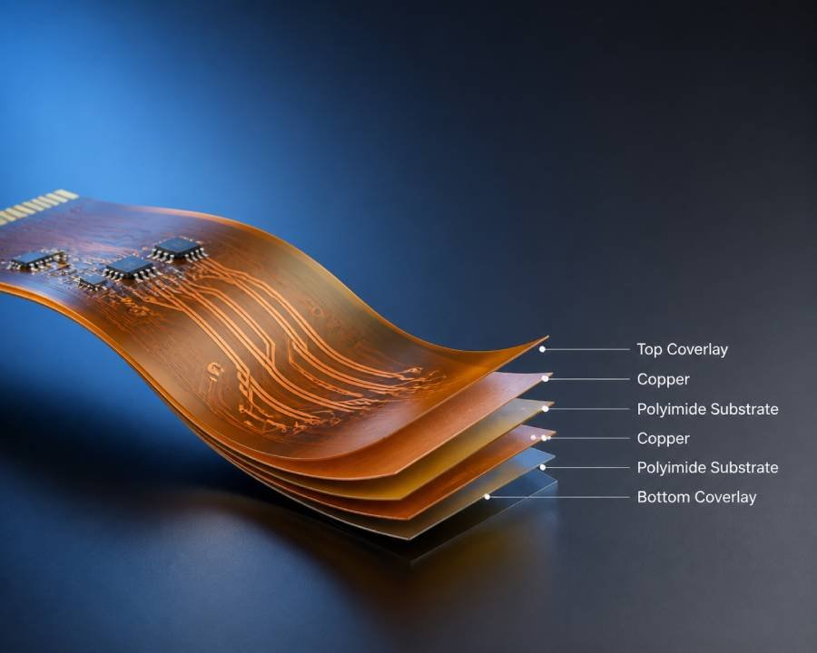
The Main Layers in a Flexible PCB Stackup
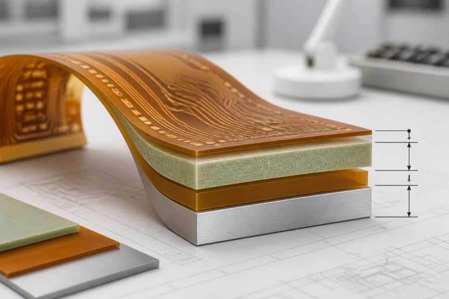
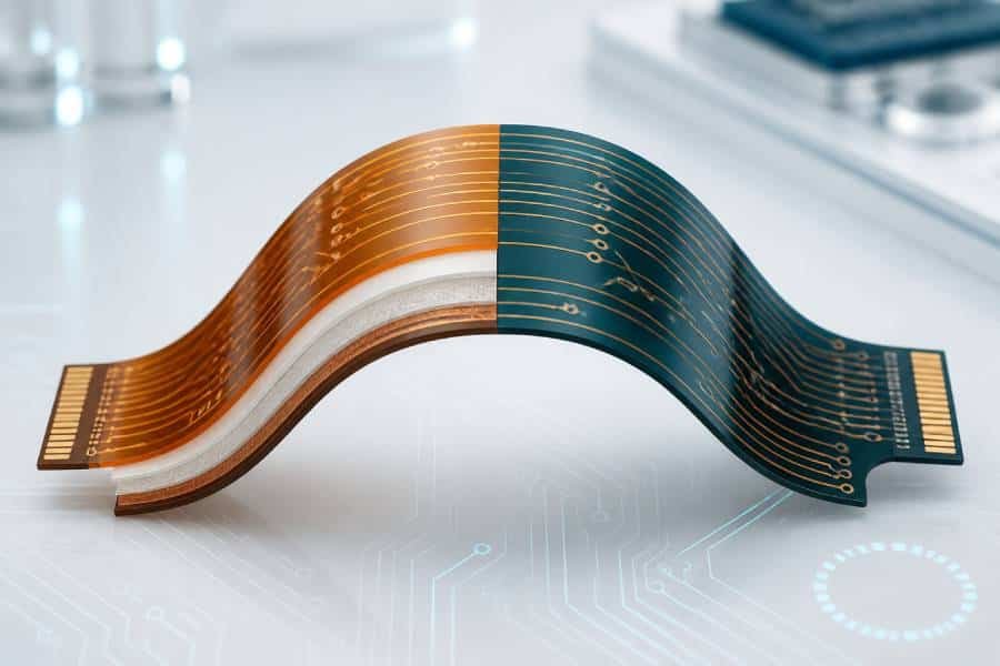
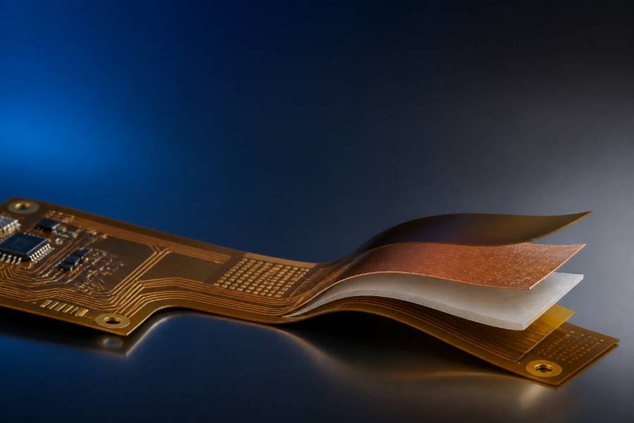
A typical flexible PCB stackup includes a base film, copper foil, optional adhesive layers, and a protective coverlay. The base film provides insulation and flexibility, the copper forms the electrical circuit, the adhesive bonds different layers when needed, and the coverlay protects exposed traces from mechanical damage and environmental exposure.
In some designs, additional materials such as stiffeners or pressure-sensitive adhesives are also used. These extra materials do not define the circuit itself, but they can significantly improve handling, connector support, assembly stability, or integration into the final product.
How Materials Affect Flexibility, Reliability, and Cost
Material selection has a direct effect on how a flex PCB performs in real applications. For example, polyimide is widely used because it combines heat resistance, toughness, and flexibility, while PET is often chosen for lower-cost applications with less demanding thermal or mechanical requirements.
The same principle applies to protective and bonding materials. Coverlay, adhesive systems, copper thickness, and even the choice of stiffener all influence bend life, manufacturability, and long-term reliability, which is why flexible PCB design is often a material trade-off rather than a single-material decision.
When Material Choice Becomes a Design Decision
In rigid PCBs, material selection may sometimes follow a standard build, but in flexible circuits it is often a core design choice from the beginning. The intended bend radius, number of flex cycles, operating temperature, and assembly process all affect whether a design should use PI, PET, adhesiveless construction, thinner copper, or stronger protection layers.
For this reason, engineers and buyers should think of flexible PCB materials as a functional system. A successful design does not simply use the “best” material in one category—it uses the right combination of materials for the application’s electrical, mechanical, and manufacturing requirements.
Polyimide vs. PET as Base Materials
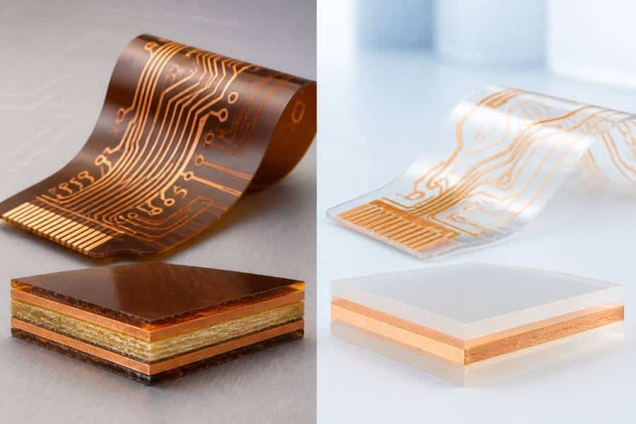
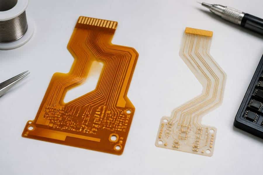
Polyimide and PET are the two most commonly discussed base films in flexible PCB construction, but they are not interchangeable in most real applications. Polyimide is the mainstream choice for flex circuits because it offers much better heat resistance, mechanical durability, and process compatibility, while PET is typically used in simpler and more cost-sensitive products.
Why Polyimide Is the Most Common Flex Substrate
Polyimide is widely used in flexible PCBs because it can handle high assembly temperatures, repeated thermal cycling, and demanding mechanical conditions. It also maintains good dimensional stability during fabrication, which makes it suitable for multilayer flex designs, rigid-flex structures, and applications that require reliable soldering performance.
Another reason PI is so common is that it supports a broad range of industrial and high-performance applications. Many manufacturers treat polyimide as the default material for flexible circuits because it combines flexibility, chemical resistance, and long-term reliability better than lower-cost alternatives.
Where PET Can Be a Practical Alternative
PET can still be a useful material when the design is simple, the thermal load is low, and cost control is the top priority. It is often chosen for static flex applications, consumer products, keypads, sensors, and other lower-end assemblies where the circuit does not need to survive solder reflow or harsh operating conditions.
Its main advantage is economics. PET is more affordable, easier to process in some basic constructions, and often suitable for high-volume applications where performance demands are limited.
PI vs. PET: Thermal, Mechanical, and Cost Differences
The biggest difference between PI and PET is thermal capability. Polyimide can tolerate the temperatures involved in SMT assembly and reflow much better, while PET generally cannot withstand direct soldering and is therefore restricted to lower-temperature applications.
Mechanically, polyimide is also the stronger option for demanding flex designs. It offers better bend endurance, better resistance to creep and dimensional change, and more reliable long-term performance in dynamic or harsh environments, whereas PET is better suited to single-bend or low-stress use cases.
From a cost perspective, PET is clearly cheaper, which is why it remains relevant in budget-driven products. However, when reliability, solderability, and wider process compatibility matter, polyimide usually delivers better overall value despite the higher material price.
Coverlay and Protective Layers
Protective layers are essential in flexible PCB construction because exposed copper traces must be insulated and shielded without losing bendability. In most flex designs, this protection is provided by coverlay rather than by the standard solder mask commonly used on rigid boards.
What Coverlay Does in a Flexible PCB
Coverlay is a protective film laminated over the outer circuit layers of a flexible PCB. It is usually made from a polyimide film plus an adhesive layer, and it serves the same basic purpose as solder mask on a rigid PCB by insulating the circuit and protecting the copper from moisture, chemicals, abrasion, and mechanical stress.
Because flex circuits are expected to bend, twist, or move, the protective layer must also remain durable under motion. That is why coverlay is widely used in flex and rigid-flex designs where long-term mechanical reliability matters.
Polyimide Coverlay vs. LPI Solder Mask
The main difference between coverlay and flexible LPI solder mask is the material form. Coverlay is a solid polyimide sheet laminated with adhesive, while flexible solder mask is a liquid coating that is applied and cured on the board surface.
In general, polyimide coverlay offers better flexibility, stronger mechanical protection, and higher durability in bend areas, which is why it remains the industry-standard solution for most flex circuits. Flexible solder mask can still be useful in fine-pitch areas or rigid-flex zones where tighter feature definition is needed, but it is usually not the first choice for high-flex regions.
How to Choose the Right Protection for Flex Areas
For circuits that will bend repeatedly or operate in demanding conditions, coverlay is usually the safer option because it is designed specifically for flex reliability. It provides robust insulation and better mechanical support over the copper traces, which helps reduce the risk of cracking or damage during use.
Flexible solder mask may be acceptable when the design has limited bending, finer openings, or mixed rigid-flex requirements. In practice, the right choice depends on the bend profile, pad geometry, assembly process, and the level of mechanical protection the application requires.

Adhesives and Adhesiveless Constructions
Adhesives play an important role in flexible PCB manufacturing because they are used to bond copper to the base film, attach coverlay, and secure stiffeners or other supporting materials. At the same time, not every flex circuit uses a traditional adhesive-based core, and the choice between adhesive-based and adhesiveless construction can strongly affect thickness, flexibility, and long-term reliability.
What Adhesives Do in Flex PCB Builds
In flexible PCB builds, adhesives are used in several places rather than in just one layer. They may bond copper foil to polyimide, attach coverlay to the circuit surface, support bondply structures, or secure stiffeners in connector and component areas.
Common flex PCB adhesives are usually acrylic- or epoxy-based, and each system has its own balance of peel strength, processing behavior, and temperature performance. Because adhesives influence both mechanical and thermal behavior, they are an important part of the overall flex material system rather than a minor assembly detail.
Adhesive-Based vs. Adhesiveless Stackups
In an adhesive-based flex construction, a separate adhesive layer is used to bond the copper foil to the polyimide core. This approach has been widely used for years because it is cost-effective, proven in production, and suitable for many standard flex-only applications.
In an adhesiveless construction, the copper is attached directly to the base film without a separate bonding layer between them. This reduces total thickness, removes one interface where fatigue or delamination can begin, and usually improves flexibility and thermal performance.
When Adhesiveless Materials Make More Sense
Adhesiveless materials are often preferred when the design must handle tight bend radii, repeated dynamic flexing, higher layer counts, or rigid-flex reliability demands. Because they create a thinner and more mechanically consistent core, they are commonly selected for higher-end flex applications where bend life and dimensional stability matter more than minimum material cost.
That does not mean adhesive-based materials are outdated. For many standard and cost-sensitive products, adhesive-based flex cores still work well and remain a practical choice, especially when the circuit is not exposed to extreme bending or harsh thermal conditions.
Copper and Conductive Layers
Copper is the conductive backbone of a flexible PCB, and its type and thickness have a major influence on both electrical performance and mechanical reliability. In flex circuits, copper is not just a conductor—it is also one of the stiffest parts of the stackup, which means its selection directly affects bendability, fatigue life, and current-carrying capability.
RA Copper vs. ED Copper in Flexible Circuits
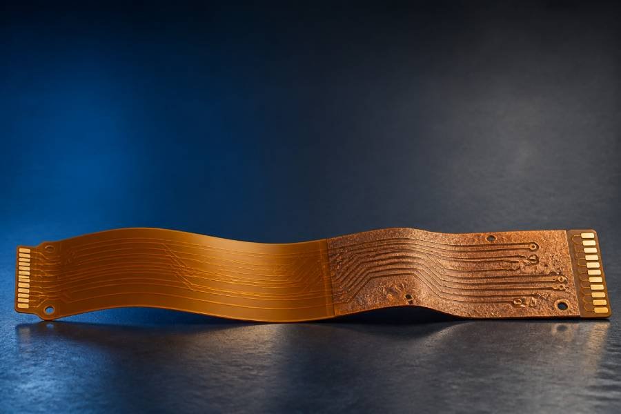
The two most common copper foils used in flexible PCBs are rolled annealed (RA) copper and electro-deposited (ED) copper. RA copper is known for higher ductility and better fatigue resistance, while ED copper is generally more economical and often used in static flex applications where repeated bending is limited.
This difference comes mainly from how the copper is made. RA copper is rolled and annealed to improve extensibility, while ED copper is formed by electrodeposition and typically has a grain structure that makes it less flexible under repeated mechanical stress.
How Copper Thickness Affects Bend Performance
Copper thickness is one of the most important mechanical design variables in flex PCB construction. Thinner copper improves flexibility and helps the circuit survive tighter bend radii, while thicker copper increases stiffness and makes the board more vulnerable to stress in bend areas.
Because of this trade-off, standard flex design practice often favors the thinnest copper that can still meet the electrical requirements. In many flex applications, common copper thicknesses fall in the range of 12 μm to 35 μm, while heavier copper is reserved for special high-current designs that can tolerate reduced flexibility.
Matching Copper Choice to Motion and Current Requirements
Copper selection should always begin with the application’s motion profile. If the circuit only bends during installation, ED copper may be sufficient, but if it must flex repeatedly during use, RA copper is usually the safer option because it offers better long-term bend reliability.
At the same time, the copper must still support the required current and thermal load. Higher current often requires thicker copper or wider traces, but both changes can reduce bend performance, so the final choice must balance electrical demands with the mechanical limits of the flex design.
Additional Materials in Flex PCB Builds
Flexible PCBs often require more than base film, copper, adhesive, and coverlay to perform reliably in real products. Additional materials such as stiffeners, shielding films, and other auxiliary layers are commonly added to improve assembly support, mechanical strength, thermal behavior, or electromagnetic performance.
What Stiffeners Are Used For
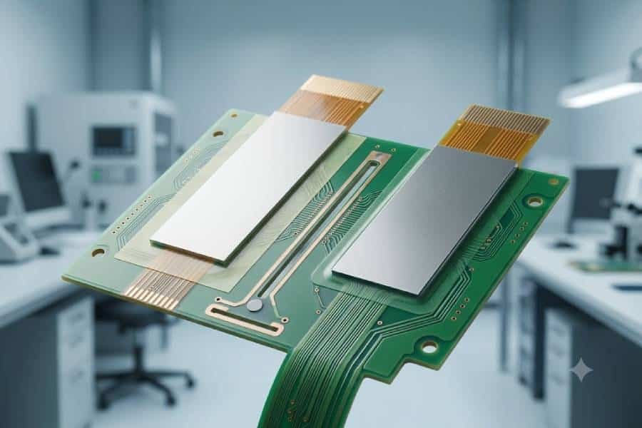
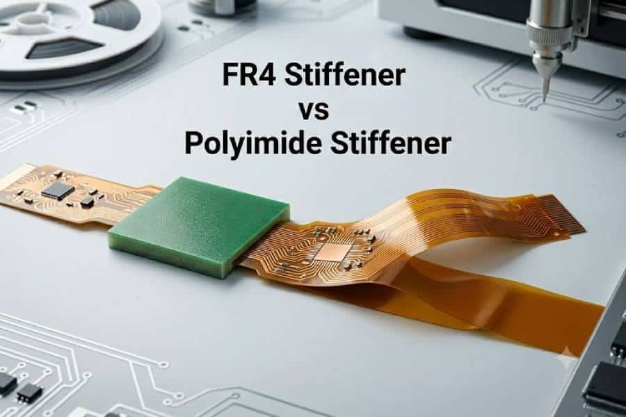
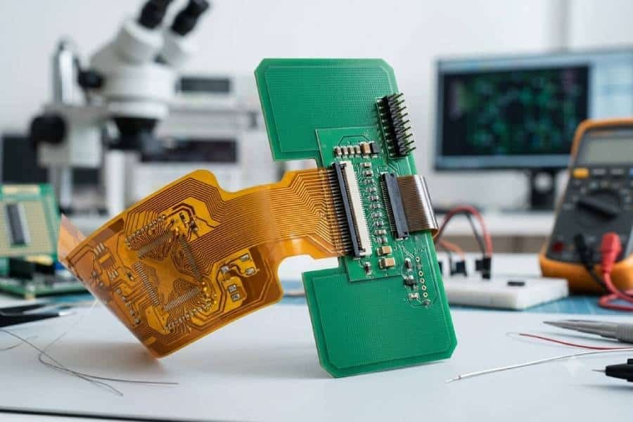
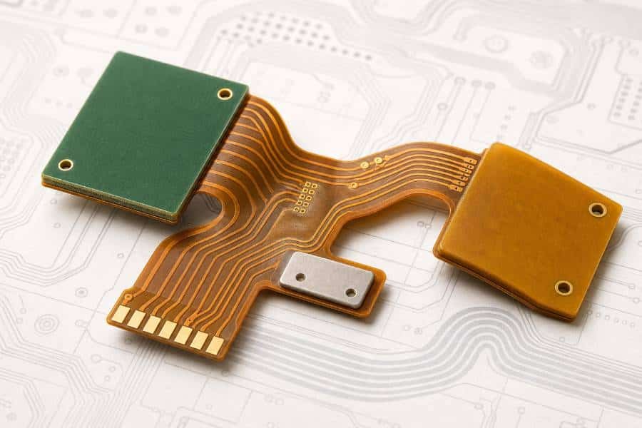
Stiffeners are added to specific areas of a flex circuit where bending is not desirable. They are commonly placed under connectors, components, solder joints, or insertion tabs to provide local rigidity, improve handling, and reduce mechanical stress in critical regions.
In many designs, stiffeners also help the flex PCB meet thickness requirements for ZIF connectors or support assembly processes that would otherwise be difficult on a fully flexible structure. This makes them one of the most practical support materials in flex circuit manufacturing.
Common Stiffener Materials and Their Roles
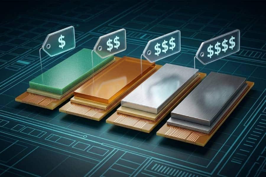
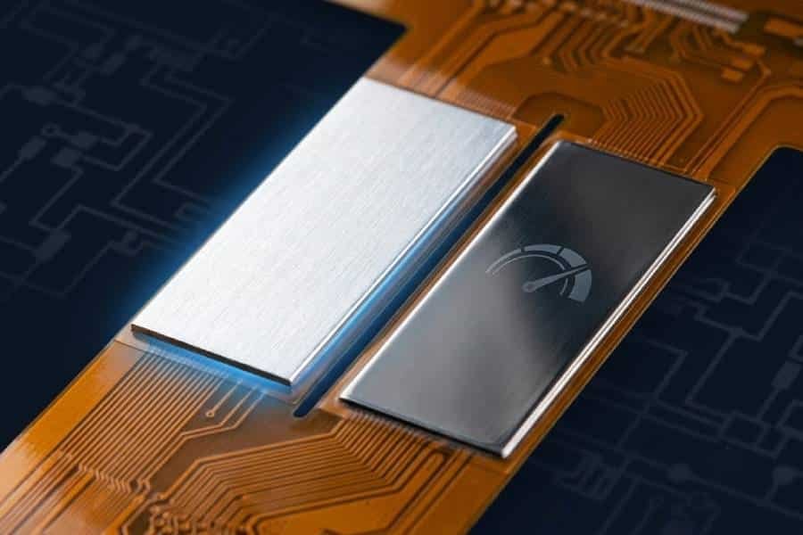
The most common stiffener materials are FR4 and rigid polyimide, although aluminum and stainless steel are also used in specialized designs. FR4 is often selected for general mechanical support, polyimide is common where a thinner or more flexible reinforcement is needed, aluminum can help with heat dissipation, and stainless steel is useful when high strength is required in a thin profile.
The right stiffener material depends on both mechanical and process requirements. A simple connector tail may only need PI or FR4, while a thermal or space-constrained design may benefit from metal reinforcement.
Other Auxiliary Materials That Improve Reliability
Other supporting materials may include EMI shielding films, thermal interface layers, spacers, or special bonding films. These materials are used when the product needs better signal protection, heat management, or structural performance beyond what the standard flex stackup can provide.
For example, EMI shielding in flexible PCBs can be achieved with shielding films, copper-based shielding layers, or conductive coatings, and each method creates a different trade-off between shielding effectiveness and bendability. That is why auxiliary materials should always be selected with the whole flex design in mind, not as afterthoughts added late in the project.
How to Choose the Right Material Stackup
Choosing the right flexible PCB stackup starts with the application, not with a single material. A good stackup must meet the mechanical mission first, then satisfy electrical, thermal, manufacturing, and cost requirements without creating avoidable reliability risks.
Static Flex vs. Dynamic Flex Applications
The first question is whether the circuit is static flex or dynamic flex. Static flex designs bend mainly during installation, while dynamic flex circuits must survive repeated movement in service, and this difference strongly affects the choice of substrate, copper type, coverlay, and total thickness.
For static applications, a standard PI-based stackup with practical cost-focused materials may be enough. For dynamic applications, designers often move toward thinner constructions, adhesiveless materials, and RA copper to improve bend life and reduce strain in the flex area.
Temperature, Bend Life, and Environmental Conditions
After defining the motion profile, the next step is to assess temperature exposure, bend radius, expected flex cycles, humidity, chemicals, and other environmental conditions. These factors determine whether a lower-cost construction is acceptable or whether the design needs higher thermal stability, stronger interface durability, and more conservative material choices.
In many cases, the stackup that looks cheapest on paper can become the most expensive if it cannot survive reflow, thermal cycling, or repeated bending. That is why material selection should always consider the whole operating environment rather than only the base film or copper type.
Balancing Performance, Manufacturability, and Cost
A reliable stackup must also be buildable and clearly documentable. Good practice is to define material type, thickness, copper weight, coverlay, adhesive system, and stiffener details early so the manufacturer can confirm feasibility and avoid ambiguity during production.
In general, the best stackup is not the one with the highest-end materials in every layer. It is the one that gives the application the required bend performance, thermal margin, and electrical behavior while still remaining manufacturable, available, and cost-effective at production scale.
Common Material Selection Mistakes
Many flex PCB failures start with material decisions that look reasonable at the quoting stage but do not match the real mechanical or thermal demands of the product. In practice, the most common mistakes are choosing materials by price alone, underestimating bend stress, and treating the stackup as a list of parts instead of an integrated system.
Choosing a Material Based on Cost Alone
One of the most common mistakes is selecting the lowest-cost base film, copper type, or protective layer without checking whether it fits the application. This often leads to premature failures in products that need higher thermal resistance, repeated bending, or stronger long-term reliability.
A low-cost material can still be the right choice, but only when the operating conditions support it. For example, polyester or ED copper may be perfectly acceptable in simple static applications, yet they become risky choices when the design moves into high-temperature, dynamic-flex, or higher-reliability environments.
Ignoring Bend Radius and Flex Cycle Requirements
Another major mistake is failing to define bend radius and expected flex cycles early in the project. When those requirements are ignored, the selected materials may not survive real use, which can cause cracked copper, intermittent opens, delamination, or complete circuit failure.
This problem becomes more serious when the design uses thicker copper, tighter bends, or places stress-sensitive features too close to the bend zone. Good material selection must always be tied to the actual motion profile of the product, not just the desired board outline.
Overlooking Stackup Compatibility
A flex PCB stackup only works well when the substrate, adhesive, copper, coverlay, and reinforcement materials are compatible with one another. Designers sometimes choose each material independently, but mismatch between these layers can increase warpage, make the board harder to build, or reduce long-term reliability.
This is also why early DFM review matters so much in flexible circuits. Manufacturers can often identify when a stackup is too thick, too unbalanced, too complex, or too dependent on uncommon materials before those issues become expensive production problems.
Application Examples
Different flexible PCB materials are suited to different industries because each application places its own demands on bending, heat resistance, reliability, and cost. In most cases, polyimide-based constructions dominate higher-performance applications, while simpler material systems may be enough for lower-stress consumer products.
Consumer Electronics
Consumer electronics are one of the largest application areas for flexible PCBs, including smartphones, tablets, cameras, wearables, and foldable devices. These products benefit from thin form factors, lightweight construction, and the ability to route circuits through tight internal spaces.
In this category, PI is commonly used for mainstream and high-performance devices because it supports compact assemblies and demanding thermal processes, while PET can still appear in lower-cost or less demanding consumer products. Material choice depends on whether the design needs simple static interconnection or repeated movement over the product’s life.
Automotive Electronics
Automotive systems use flexible PCBs in dashboards, sensors, lighting modules, battery systems, cameras, and infotainment assemblies. These applications often face vibration, temperature variation, and compact packaging constraints, so material selection has a major effect on long-term reliability.
For many automotive applications, PI-based flex circuits are preferred because they can tolerate higher temperatures and harsher environments better than lower-end alternatives. The more demanding the environment becomes, the more important it is to balance substrate, copper, and protection layers carefully.
Medical and Industrial Devices
Medical and industrial electronics often require flexible circuits that are compact, durable, and dependable over long service periods. Typical examples include wearable monitors, hearing aids, portable diagnostic tools, imaging systems, industrial sensors, and moving control assemblies.
These applications often benefit from polyimide-based flex materials because they offer better thermal stability, insulation reliability, and mechanical durability. In healthcare and industrial systems, the material stackup is usually chosen more conservatively because failure costs are much higher than in low-end consumer devices.
Conclusion
Choosing flexible PCB materials is not about finding one universally “best” option. It is about building the right material system for the job by balancing substrate choice, copper type, coverlay, adhesive structure, bend requirements, thermal demands, and cost targets.
For most demanding flexible PCB applications, polyimide remains the preferred base material because it offers the strongest combination of heat resistance, durability, and process compatibility. PET still has value in lower-cost and lower-stress designs, but it is usually better suited to simpler static applications than to high-reliability flex circuits.
The same principle applies to the rest of the stackup. Coverlay, adhesives, copper foil, and auxiliary materials such as stiffeners all affect final performance, so they should be selected together rather than one by one.
In practice, the best results come from matching materials to the real application environment and confirming the stackup with an experienced PCB manufacturer early in the design process. That approach helps avoid unnecessary cost, improves manufacturability, and leads to a more reliable flex PCB design from prototype to volume production.