Design Guidelines for FR4 Stiffeners in Flex PCB SMT Areas: Best Practices & Key Considerations

This comprehensive guide covers the critical design specifications and practical considerations for using FR4 stiffeners in Flex PCB SMT areas. From proper thickness selection and coverage rules to thermal management and common pitfalls, learn how to significantly improve assembly reliability and product durability in your flexible circuit projects.
fr4 stiffener design guidelines for flex pcb smt areas

Table of Contents

In today’s fast-evolving electronics industry, flexible printed circuit boards (Flex PCBs) have become essential for compact, lightweight, and high-performance devices such as wearables, automotive electronics, medical equipment, and foldable consumer products. While Flex PCBs offer excellent bendability and space-saving benefits, their inherent flexibility creates challenges during Surface Mount Technology (SMT) assembly.

One of the most effective and widely adopted solutions is the use of FR4 stiffeners in SMT areas. Properly designed FR4 stiffeners significantly improve assembly reliability, protect solder joints, and prevent component displacement. This article provides comprehensive design guidelines, key specifications, and critical considerations for using FR4 stiffeners on Flex PCBs.

Flex PCB with FR4 Stiffener in SMT Area

Why Flex PCBs Need Stiffeners in SMT Areas

Flex PCBs are constructed using polyimide (PI) films, which offer outstanding flexibility but relatively low mechanical rigidity. In SMT regions, where heavy components like BGAs, connectors, ICs, and passive devices are mounted, this softness can lead to several issues:

  • Excessive bending during pick-and-place and reflow processes
  • Solder joint cracking due to mechanical stress
  • Component misalignment or tombstoning
  • Reduced assembly yield and long-term reliability problems

FR4 stiffeners address these challenges by locally increasing board rigidity while maintaining the flexibility of other areas. Compared to alternatives like stainless steel, aluminum, or pure polyimide stiffeners, FR4 offers an excellent balance of cost, processability, and thermal compatibility with standard PCB manufacturing.

What is FR4 Stiffener?

FR4 is a glass-reinforced epoxy laminate material widely used in rigid PCBs. When applied as a stiffener to Flex PCBs, it is typically bonded to the back or front side of the flexible circuit in targeted zones.

Common specifications include:

  • Thickness: 0.1mm to 2.0mm (most common: 0.3mm, 0.5mm, 0.8mm, 1.0mm)
  • Single-sided, double-sided, or selective (partial) stiffening
  • Bonding methods: Thermal bonding adhesive (acrylic or epoxy), Pressure Sensitive Adhesive (PSA), or 3M adhesive films

The choice of thickness and coverage area directly impacts both mechanical performance and the overall flexibility of the final product.

Technical cross-section diagram of a flexible PCB with an FR4 stiffener, showing polyimide layers, copper traces, adhesive layer, and SMT components on a dark background.

Key Design Specifications for FR4 Stiffeners

1. Coverage Area and Size Requirements

  • The FR4 stiffener should cover all SMT components plus an additional margin of 0.5mm to 1.0mm beyond the outermost component edges.
  • For high-density designs, extend coverage to include test points and large copper areas.
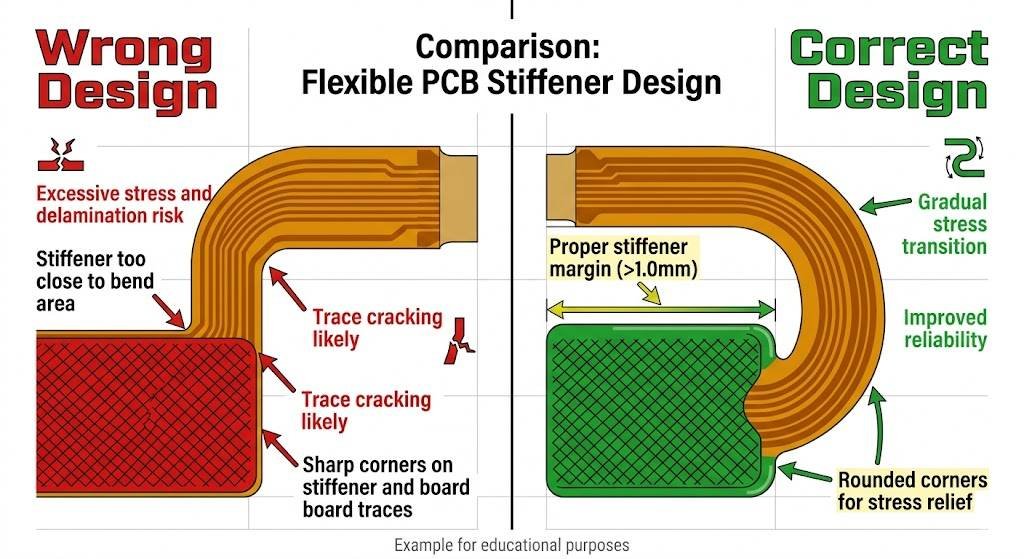
  • Avoid covering dynamic bend areas. Maintain at least 1.5mm–3mm clearance between the stiffener edge and the bend line.

Top view technical diagram of a flexible PCB showing recommended FR4 stiffener coverage in the SMT area, highlighting a 0.5mm to 1mm margin with red lines, dimensions, and circles.

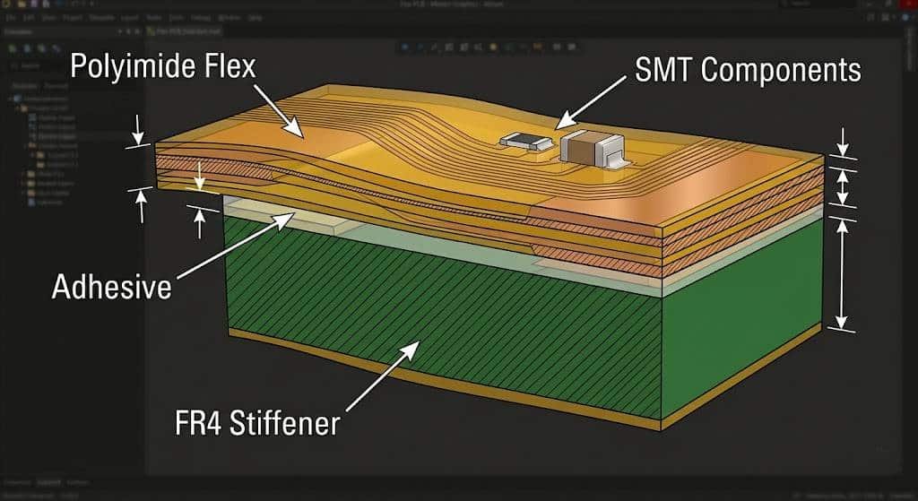
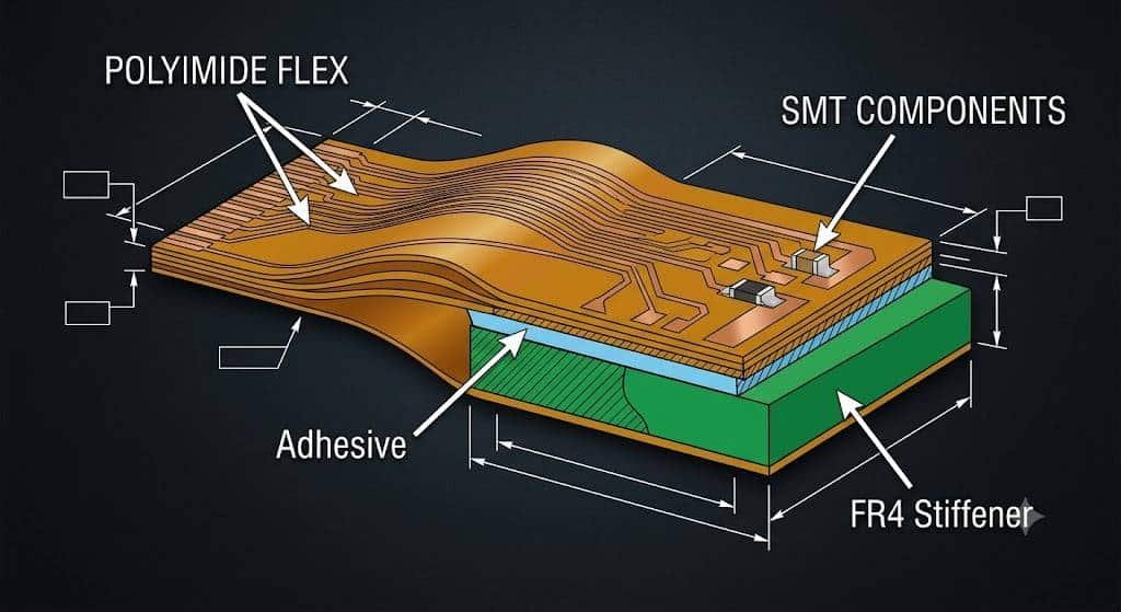
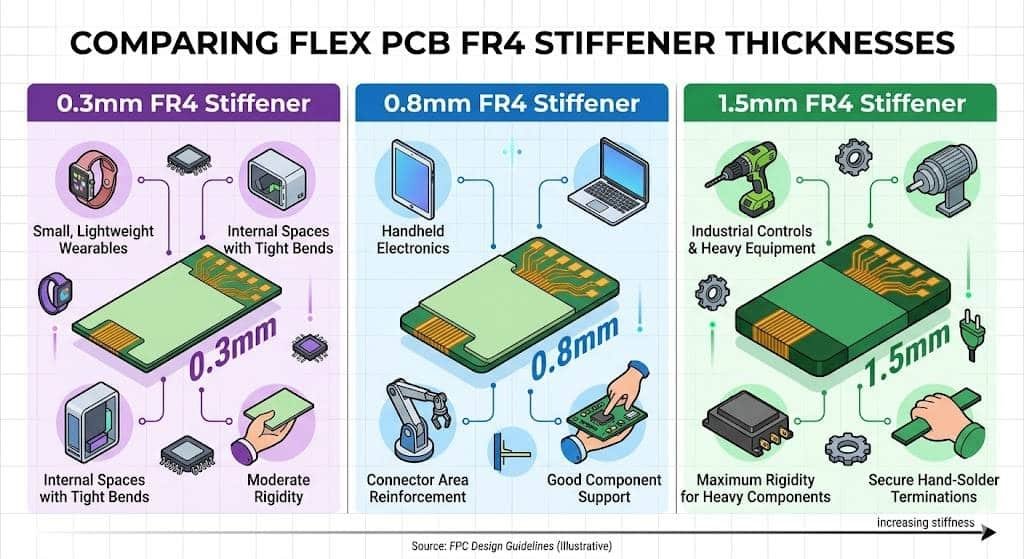
2. Thickness Selection Guidelines

Component TypeRecommended Stiffener ThicknessNotes
Small passives (0201-0402)0.2 – 0.5mmLight support
QFN, BGA, Connectors0.6 – 1.2mmStandard choice
Heavy components / High vibration1.0 – 2.0mmMaximum rigidity

An engineering infographic comparing Flex PCB FR4 stiffener thicknesses: 0.3mm (wearables, tight bends), 0.8mm (handheld electronics, connectors), and 1.5mm (industrial controls, heavy components, increasing stiffness)

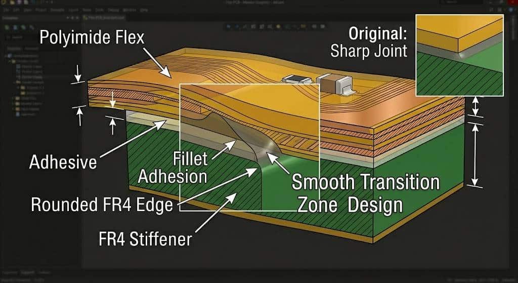
3. Shape and Corner Design

  • Use rounded corners with a minimum radius of 0.5mm to reduce stress concentration.
  • Avoid sharp edges that may cut into the flex material during repeated bending.
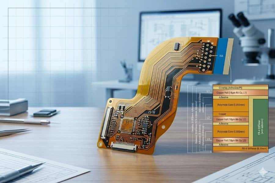
  • Incorporate fiducial marks and tooling holes on the stiffener for precise alignment during lamination and SMT.

Technical illustration of a flexible PCB showing a smooth transition zone design, featuring a rounded FR4 edge, fillet adhesion, and an inset comparison with a sharp joint.

4. Tolerance and Alignment

  • Outline tolerance: ±0.1mm
  • Position tolerance: ±0.15mm
  • Adhesive thickness control: 0.025mm – 0.05mm

Critical Considerations and Best Practices

Thermal Expansion Matching FR4 and polyimide have different Coefficients of Thermal Expansion (CTE). During reflow soldering (peak temperature ~260°C), mismatched expansion can cause warpage or delamination. To mitigate this:

  • Use high-Tg FR4 material when possible
  • Optimize adhesive selection for high-temperature resistance
  • Consider symmetrical stiffener design on both sides for complex boards

Transition Zone Design The area where the stiffener ends and the flexible section begins is critical. A sharp transition creates stress points. Best practices include:

  • Adding a gradual taper or stepped thickness
  • Using adhesive with controlled flow to create a smooth fillet
  • Keeping the transition zone free of copper traces when possible

SMT Process Compatibility

  • Ensure stiffener flatness (warpage < 0.5%) to maintain good solder paste printing results
  • Verify that the adhesive can withstand reflow temperatures without outgassing
  • For double-sided SMT, balance stiffener placement to prevent board bowing

Mechanical Reliability

  • In vibration or drop-test environments, thicker FR4 provides better protection
  • For products requiring repeated flexing (dynamic applications), limit stiffener proximity to bend areas and perform flex-fatigue testing

Manufacturing Feasibility

  • Precise alignment between FR4 stiffener and Flex PCB is crucial. Professional manufacturers use automated optical alignment systems.
  • Air entrapment and voids must be eliminated through proper vacuum lamination or pressure control.
flexible pcb stiffener design comparison wrong vs correct
An engineering comparison infographic of flexible PCB stiffener designs, showing a 'Wrong Design' in red with excessive stress points, and a 'Correct Design' in green with proper margins, rounded corners, and gradual stress transition for improved reliability.

Common Mistakes to Avoid

  • Placing stiffener edges too close to bend zones, leading to premature cracking.
  • Choosing overly thick stiffeners that restrict required flexibility.
  • Insufficient margin around components, causing poor solder fillet formation.
  • Ignoring adhesive thermal properties, resulting in delamination after thermal cycling.
  • Poor positioning of tooling holes, causing misalignment during assembly.

Real-World Applications

Consumer Electronics Smartwatches and TWS earbuds commonly use 0.5–0.8mm FR4 stiffeners under Bluetooth chips and batteries for stable SMT performance.

Automotive Car camera modules and dashboard electronics require robust stiffeners to survive harsh vibration and temperature environments.

Medical Devices Flexible endoscopes and wearable health monitors benefit from selective FR4 reinforcement to protect sensitive sensors while allowing ergonomic bending.

At PCBelec, we have supported numerous projects where proper FR4 stiffener design increased first-pass yield by over 15% and significantly improved product durability.

Conclusion

Using FR4 stiffeners in Flex PCB SMT areas is both an art and a science. Following the design guidelines outlined above helps manufacturers achieve higher assembly yields, better mechanical reliability, and longer product lifespans.

A well-designed stiffener solution balances rigidity where needed with flexibility where desired. Partnering with an experienced Flex PCB manufacturer like JHYPCB ensures your design is optimized from the DFM stage through final production.

Ready to optimize your Flex PCB design? Submit your Gerber files today for a free DFM analysis and expert recommendations on FR4 stiffener implementation. Our team specializes in Flex PCBs, Rigid-Flex PCBs, and complex multilayer solutions.

Contact JHYPCB for competitive pricing, fast turnaround, and technical support on your next flexible circuit project.

Related Reading

About us

JHYPCB is a leading PCB prototyping, PCB manufacturing and assembly service provider in China, offering quick turn PCB prototyping, multi-layer PCB manufacturing and turnkey PCB assembly services.

Recent Posts

PCB assembly service
Scroll to Top