Table of Contents
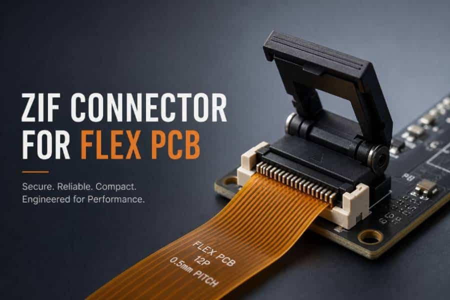
ZIF connectors, short for Zero Insertion Force connectors, are a widely used solution for connecting flex PCB and FPC assemblies with minimal mechanical stress. Instead of forcing the flex tail into place, a ZIF connector uses a locking mechanism to secure the circuit after insertion, helping protect delicate traces and improve assembly reliability. They are especially valuable in compact electronic designs where consistent contact, easy installation, and repeated mating performance are important.
In this article, we’ll explain what a ZIF connector is, how it works, why it is commonly used in flex PCB design, and what to consider when pairing it with a stiffener. We’ll also look at typical applications and the key design points that help ensure a stable and reliable connection.
What Is a ZIF Connector?
A ZIF connector, short for Zero Insertion Force connector, is a type of electrical connector designed to let a flex PCB or FPC tail slide into place with very little insertion force. After the circuit is inserted, a locking mechanism such as a slider or flip latch secures the contact area and maintains a reliable electrical connection. This makes ZIF connectors especially useful for flexible circuits that need low-stress assembly and stable performance in compact devices.
In flex PCB applications, ZIF connectors are commonly used because they reduce the risk of damaging delicate copper traces and help simplify the assembly process. They are one of the most widely used interconnect methods for flexible circuits, especially when the design needs repeated mating, easy installation, and a thin connection interface.
Technically, a ZIF connector is not “force-free” in every sense; the insertion stage requires little force, but the connector still depends on contact pressure and locking force after mating. That is why the connector interface, pad pitch, circuit width, and thickness must match the manufacturer’s specification very closely.
How Does a ZIF Connector Work?
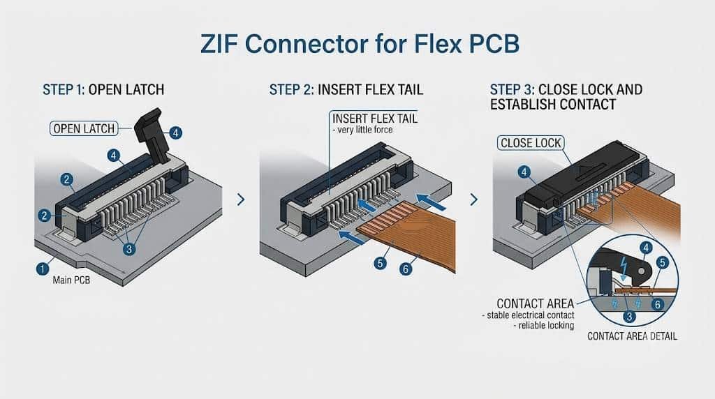
A ZIF connector works by separating insertion from contact locking. First, the locking actuator is opened, the flex tail is inserted into the connector slot with very little force, and then the actuator is closed to clamp the circuit into position and create a stable electrical contact.
The key idea is that the flex circuit does not have to be pushed hard into the connector. Instead, the connector uses a slider, flip-lock, or similar mechanism to apply contact pressure after insertion, which helps protect delicate flex tails and improves repeatable assembly performance.
In practical terms, the process usually follows four steps: open the connector, insert the flex tail in the correct orientation, close the latch, and verify that the tail is fully seated and locked. This simple sequence is one reason ZIF connectors are popular in compact electronics and flexible circuit applications.
It is also important to remember that “zero insertion force” does not mean the connector has no force at all. The contact area still depends on proper locking pressure and accurate matching of thickness, pitch, and pad alignment to maintain a reliable connection.
Why Use ZIF Connectors in Flex PCB Design?
ZIF connectors are one of the most practical ways to connect a flex PCB or FPC to a rigid board because they combine low insertion stress, easy assembly, and reliable contact retention. Instead of forcing the flex tail into a tight contact area, the connector accepts the tail with minimal force and then locks it in place, which helps protect delicate copper traces and reduces the risk of assembly damage.
Another major advantage is manufacturability. ZIF connectors simplify assembly, can reduce the need for extra mating parts, and are often chosen when the design calls for a compact, cost-effective interconnect with repeatable performance. They are also widely used because they support frequent connection and disconnection better than many direct-contact methods, making them suitable for products that may need servicing, testing, or modular replacement.
From a design perspective, ZIF connectors are especially valuable when the flex tail is thin, space is limited, and the connection area must stay mechanically stable over repeated use. That is why they are common in consumer electronics, displays, medical devices, and other compact systems where dependable signal transfer matters.
ZIF Connector vs. Other Flex PCB Connection Methods
Although ZIF connectors are the most common choice for many flex PCB and FPC assemblies, they are not the only option. Flexible circuits can also be connected by soldering, LIF connectors, unsupported flex fingers, crimped contacts, or other direct interconnect methods, depending on the electrical, mechanical, and manufacturing requirements of the design.
Compared with LIF connectors, ZIF connectors require less force during insertion and usually provide a more user-friendly assembly process. LIF designs are often simpler and sometimes cheaper, but they generally trade off some retention and reliability compared with ZIF systems.
Compared with direct soldering, ZIF connectors are much easier to assemble and rework, and they avoid concentrating thermal and mechanical stress on the flex tail. Soldering can work well in some designs, but it needs strong strain relief and careful alignment, especially when the flex section may move or experience vibration over time.
Compared with unsupported flex fingers or other direct-contact approaches, ZIF connectors usually offer a more controlled and repeatable interface. This matters when the product needs frequent mating cycles, compact packaging, and stable contact quality in production or field service conditions.
In short, ZIF is usually the best choice when the design priorities are easy assembly, low stress, repeatable connection, and compact form factor. Other methods may be better when the application is permanent, high-current, unusually cost-sensitive, or mechanically specialized.
Key Design Considerations for ZIF Connectors
When designing for a ZIF connector, the first rule is to follow the connector manufacturer’s landing pattern, pitch, and thickness requirements exactly. ZIF interfaces are very sensitive to dimensional accuracy, and a tail that is too thick, too thin, or misaligned can cause poor contact or assembly failure.
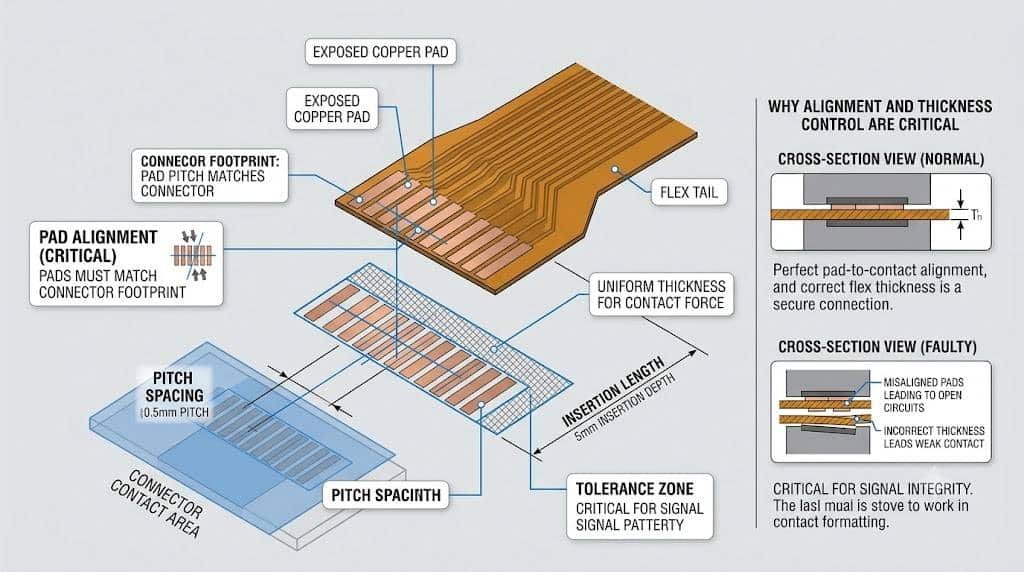
Pitch and pad alignment are the starting point. The pad width, spacing, and contact position must match the connector’s specified footprint, because even small deviations can affect insertion and electrical reliability.
Tail thickness is one of the most important factors in ZIF design. Many connectors are designed around a narrow accepted thickness range, and common guidance points to a tail thickness around 0.012 inches, with the exact requirement depending on the connector model. If the flex tail does not meet that range, the connector may not lock correctly or may not maintain a stable contact interface.
Insertion length and overlap also matter. The circuit must extend far enough into the connector for the contacts to engage properly, but not so far that it interferes with the locking mechanism or distorts the tail. For robust designs, overlap between the pad area and the connector contact zone helps reduce trace damage during insertion.
Tolerance control is critical in real production. Interface guidance from connector and rigid-flex design materials emphasizes maintaining tight thickness tolerances, often around +/- 0.05 mm, with even tighter targets for advanced requirements. That means the fab drawing, stiffener thickness, coverlay opening, and connector spec all need to be coordinated before layout is finalized.
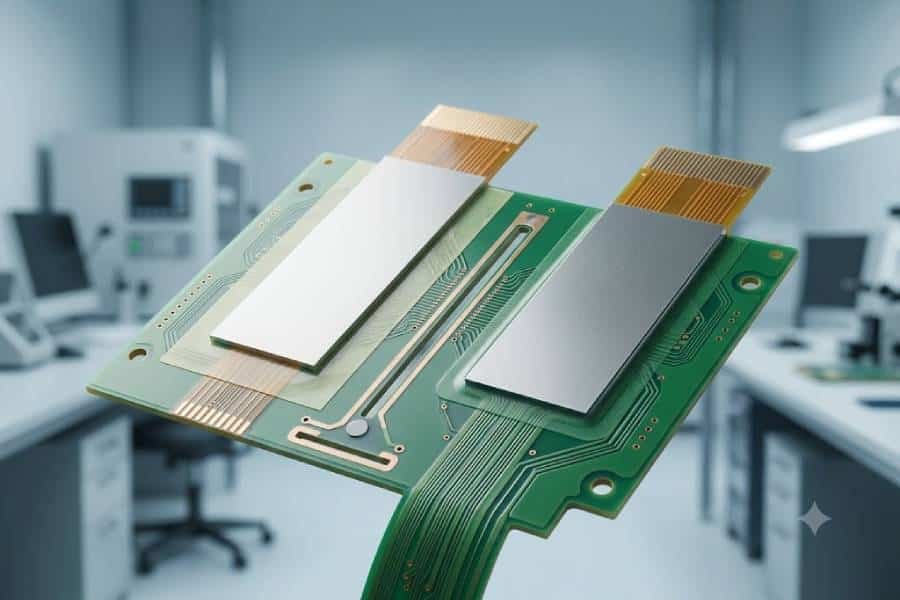
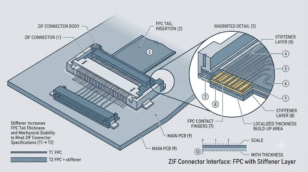
Stiffener selection is often part of the ZIF design itself, not an afterthought. In many flex designs, polyimide or FR-4 stiffeners are added under the contact fingers to increase localized thickness and help the tail meet the connector specification. This is especially important when the flex section would otherwise be too thin or mechanically unstable in the connector zone.
Practical design checklist
- Confirm connector pitch and landing pattern from the datasheet.
- Verify target tail thickness and stiffener thickness together.
- Keep pad alignment and coverlay openings within tolerance.
- Check insertion depth and contact overlap before release.
- Specify the ZIF area clearly in the fabrication drawing.
ZIF Connector and Stiffener: How They Work Together
In many flex PCB designs, the ZIF connector and the stiffener are a matched pair rather than two separate choices. The connector defines the thickness and contact requirements, while the stiffener helps the flex tail meet those requirements by adding localized rigidity and thickness in the contact area.
This is especially important because many ZIF connectors are built around a specific tail thickness, commonly around 0.012 inches or 0.3 mm, and a bare flex circuit is often too thin to fit or lock properly on its own. Adding a stiffener under the finger area is a practical way to bring the circuit into the correct thickness range and improve connector engagement.
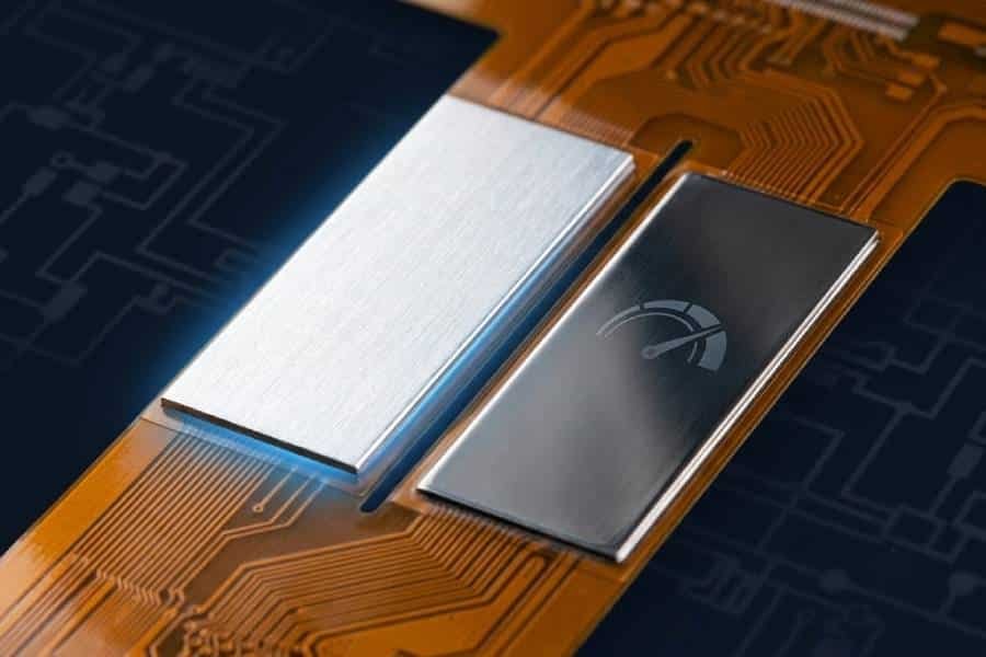
The stiffener also improves mechanical stability. It helps the flex tail resist bending or distortion during insertion, which reduces the risk of trace damage and makes assembly more repeatable, especially when the connection area is narrow or when the circuit must enter the connector at an angle.
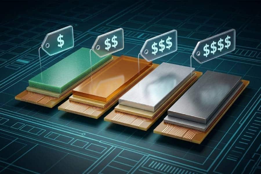
From a materials standpoint, polyimide and FR-4 are the most common stiffener choices, and the right option depends on the required thickness, rigidity, and processing needs. Polyimide is often used when the goal is to meet ZIF thickness while keeping the structure lightweight, while FR-4 is more rigid and useful when the connector area needs stronger support.
A good ZIF/stiffener design should also include proper overlap. Design guidance commonly recommends that the stiffener overlap the contact area enough to support the finger region and reduce stress at the pad-to-flex transition, which improves durability in both static and dynamic applications.
In short, the stiffener is what makes many ZIF connections physically possible and mechanically reliable. Without it, the tail may be too thin, too flexible, or too fragile to maintain a stable connection over repeated use.
Common Applications of ZIF Connectors
ZIF connectors are widely used in consumer electronics, especially where a compact flex cable needs to connect a display, touchscreen, camera module, or other internal component to a main PCB. Their low-stress locking design makes them a good fit for smartphones, tablets, laptops, and wearables where space is limited and assembly consistency matters.
They are also common in display modules, including LCD and OLED assemblies, because these products often rely on flexible tails that must be inserted cleanly and held in place with a stable contact interface. In many display-related designs, the ZIF connector is the simplest and most reliable way to terminate the flex circuit.
In medical devices, ZIF connectors are used when the design requires dependable signal transfer in a small package and may need serviceability or modular replacement. Their low insertion force helps reduce wear on delicate interconnects, which is valuable in compact equipment that is assembled and maintained carefully.
They are also used in automotive and industrial electronics, including infotainment systems, control modules, and other compact subsystems that need reliable flex-to-board interconnection. These environments may demand more attention to durability, mating cycles, and environmental conditions, so the connector choice must match the application requirements.
A simple way to think about this section is: if a product needs a thin flex tail, stable contact, and repeatable assembly in a tight space, ZIF connectors are often a strong candidate. That is why they appear so often across consumer, display, medical, and industrial designs.
Frequently Asked Questions
ZIF connectors allow the flex tail to be inserted with almost no force and then locked in place, while LIF connectors still require some insertion force and usually have a simpler retention structure. In general, ZIF is better when you want easier assembly and stronger repeatability, while LIF may be used in simpler or lower-cost designs.
Not always, but many flex PCB designs use a stiffener in the connector area to reach the thickness required by the ZIF connector. A stiffener also helps make the tail flatter and more stable during insertion, which improves connection reliability.
A common target is around 0.012 inches, or about 0.3 mm, though the exact thickness depends on the connector model and datasheet. Some designs also use accepted ranges around 0.012 inches plus or minus 0.002 inches, so the connector specification must always be checked first.
ZIF connectors are available in different pitches, and 0.5 mm and 1.0 mm are common in many flex applications. The right pitch depends on the connector family, available space, and the density of the flex circuit pads.
Yes. ZIF connectors are often used in rigid-flex and flex-to-board applications where the flex section needs to terminate into a stable connector interface on the rigid board. In those cases, the connector and the PCB stackup should be planned together to ensure proper fit and reliability.
They are designed for repeated insertion and removal, but the actual lifetime depends on the connector quality, locking mechanism, and how carefully the cable is handled. If the latch or contacts are damaged, the connector may no longer retain the flex tail reliably.
Conclusion
ZIF connectors remain one of the most practical and reliable ways to terminate a flex PCB or FPC in compact electronic designs. When the connector thickness, pad layout, and stiffener requirements are matched correctly, they provide a low-stress interface that supports easy assembly and stable long-term performance.
For flex PCB projects that need dependable connectivity, the key is not just choosing a ZIF connector, but designing the entire interface correctly from the start. That means paying attention to pitch, thickness, alignment, and stiffener support so the final assembly works as intended.
If you are designing a flex circuit for a compact product, ZIF connectors are often the first solution worth considering.