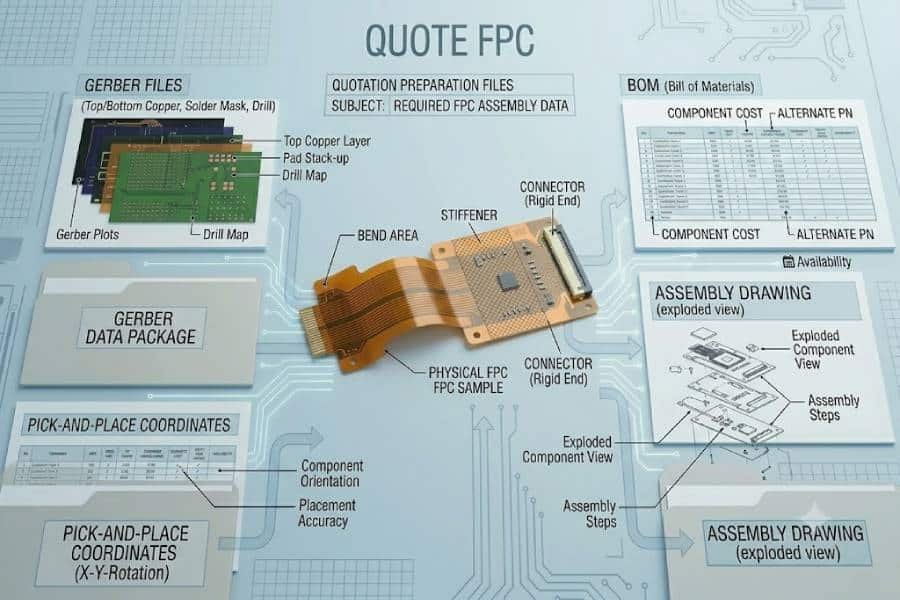
Getting a flexible PCB assembly quote starts with sending the right files. In most cases, the core quote package includes Gerber files, a BOM, a pick-and-place file, and an assembly drawing, while added details such as stack-up notes, bend information, and test requirements can help the supplier review the build more accurately and respond faster.
For buyers, the goal is not simply to send enough data, but to send a package that is complete, consistent, and easy for the engineering team to understand. Google’s guidance for high-quality content also favors direct answers, clear headings, and content organized for real users, which is the same approach that works best for a quote-readiness article like this one.
What to Send First
If you want the fastest and most accurate flexible PCB assembly quote, start with four core items: Gerber files, a BOM, a pick-and-place file, and an assembly drawing. These documents give the manufacturer the minimum information needed to review board layout, identify components, verify placement data, and understand how the board is supposed to be assembled.
For flexible PCB projects, it is also helpful to include any notes that affect the physical construction of the board. Information about stack-up, stiffeners, bend-sensitive areas, and special connector regions can help the supplier identify process risks earlier, especially when the project is more complex than a standard rigid SMT assembly.
A good first submission should answer three basic questions for the quoting team: what is the board, what parts go on it, and are there any special build conditions? When those answers are clear from the beginning, the supplier can spend more time evaluating the job and less time asking follow-up questions.
Essential Files for an Accurate Quote
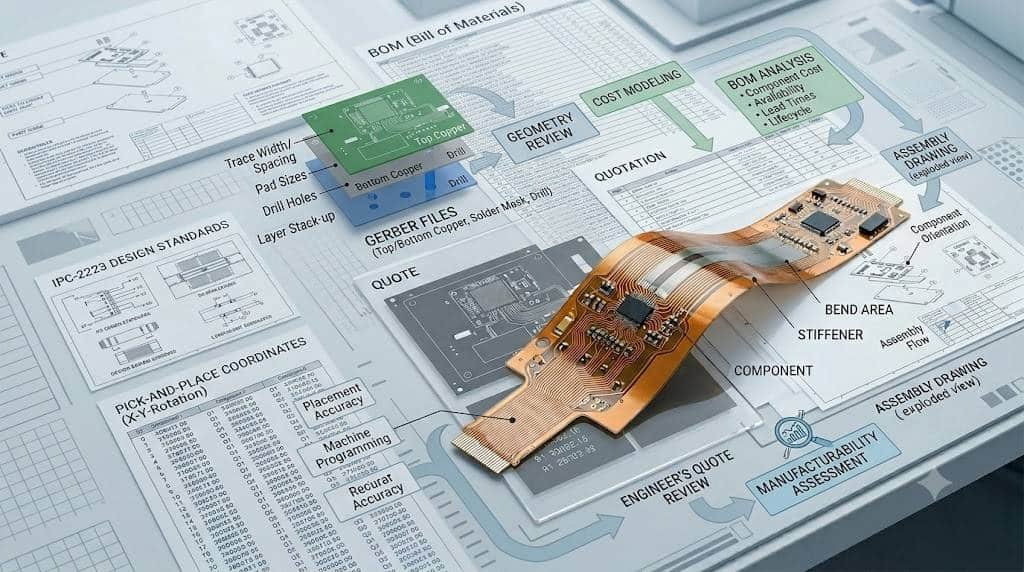
The most important files for a flexible PCB assembly quote are the Gerber files, BOM, pick-and-place file, and assembly drawing. Together, these documents allow the manufacturer to review the physical board, calculate material needs, confirm SMT placement information, and understand any assembly-specific instructions before issuing pricing and lead time.
Gerber files define the physical board data used for fabrication review. They typically include copper layers, solder mask, silkscreen, and related board information, and they help the supplier confirm whether the design can be manufactured as submitted.
The BOM, or bill of materials, identifies every component required for the build. At a minimum, it should include part reference, manufacturer part number, and quantity so the sourcing team can verify availability and estimate the real material cost.
A pick-and-place file provides X-Y coordinates, rotation, and side-of-board data for each placed component. This file is especially important for SMT builds because it helps verify the assembly data and reduces the need for manual interpretation during review.
An assembly drawing adds visual instructions that may not be obvious from raw CAD export data alone. It can show orientation, polarity, special notes, and placement intent, which becomes even more useful when the design includes dense layouts, mixed technology, or unusual component types.
What Each File Is Used For
Each file in the quote package serves a different purpose, and the engineering team reads them together rather than separately. If one file is missing or does not match the others, the quote may be delayed until the supplier can confirm which data set is correct.
The Gerber files are used to understand the board itself. They show the conductor pattern, solder mask, silkscreen, and outline, allowing the supplier to review both manufacturability and any flex-specific layout considerations that may affect production.
The BOM is used to confirm what components must be purchased and assembled. It tells the manufacturer exactly which parts belong on the board, how many are needed, and whether the sourcing team has enough detail to price the material accurately.
The pick-and-place file is used to locate each SMT component on the PCB. It gives the assembler the coordinate and rotation data needed to verify placement consistency and prepare machine-ready assembly information.
The assembly drawing is used as a visual reference for details that are easier to confirm in drawing form than in spreadsheet or coordinate form. This includes polarity marks, component orientation, hand-assembly notes, or special instructions for connectors and other critical parts.
For flexible PCB assemblies, supplemental design notes can be just as important as the core files when the physical behavior of the circuit matters. If the design includes stiffeners, bend regions, stack-up requirements, or construction constraints, those details help the supplier understand how the flex should be built and handled rather than making assumptions from the layout alone.
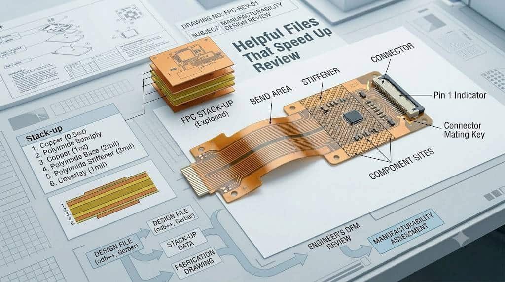
Helpful Files That Speed Up Review
Some files are not always mandatory for the first quote request, but they can make the review process much faster and more accurate. For flexible PCB assembly, supporting documents such as stack-up drawings, mechanical drawings, fabrication notes, and test requirements often help the engineering team understand the full build without sending repeated follow-up emails.
A stack-up drawing is especially useful when the project includes multiple materials, controlled thickness, special copper weights, or flex-specific construction details. In more complex flexible or rigid-flex designs, the stack-up can clarify layer order, material type, finished thickness, and construction intent that may not be obvious from Gerber data alone.
A mechanical drawing can also speed up review by clarifying dimensions, cutouts, tolerances, bend areas, and fit-related constraints. This matters even more in flex designs, where board shape and movement can affect handling, stiffener placement, and final assembly planning.
Fabrication notes and special requirement documents are helpful whenever the build goes beyond a standard process. Notes about surface finish, special materials, connector areas, or unusual handling conditions help the supplier quote the correct process path from the start rather than relying on assumptions.
If the project has defined inspection or validation needs, test requirements should be shared early as well. Information about AOI, X-ray, flying probe, functional test, or first article inspection can affect both pricing and lead time, so it is better to include these expectations during quotation instead of adding them after release.
Common Missing Details
Many quote delays are caused not by missing major files, but by missing details inside an otherwise complete package. Even when the Gerbers, BOM, and placement data are attached, the supplier may still need clarification if critical specifications, revision data, or sourcing information are incomplete.
One of the most common issues is a BOM without enough purchasing detail. Missing manufacturer part numbers, unclear package names, incomplete electrical values, or vague internal descriptions make it harder to confirm price and availability accurately.
Another frequent problem is a revision mismatch between the Gerber files, BOM, and pick-and-place data. If one file set reflects a newer release than another, the quote often pauses until the buyer confirms which revision should be used.
Customers also often forget to specify quantity and target lead time. Those two details directly affect sourcing strategy, scheduling, and whether the supplier treats the project as a prototype, small batch, or production build.
For flexible PCB projects, missing construction and handling notes can create extra uncertainty. Details such as bend areas, stiffener location, stack-up, finished thickness, special materials, or connector constraints can all influence manufacturability and final cost.
It is also common to leave out assembly and test expectations such as DNP parts, approved alternates, inspection scope, or special process requirements. These details may seem minor, but they often determine whether the initial quote is accurate or only a preliminary estimate.
How to Package Files Before Sending
The easiest way to reduce confusion is to package all quote data into one clearly labeled folder or ZIP archive before sending it. Many PCB and PCBA suppliers specifically ask customers to submit Gerber data, BOM, centroid data, drawings, and notes as one organized release package instead of scattering them across multiple emails.
Start by making sure every file belongs to the same design revision. The revision should match across the Gerber files, BOM, assembly drawing, notes, and placement data, because even a small mismatch can delay the quote while the engineering team checks which data set is active.
It also helps to use clear file names that identify the project, revision, and file type. Simple names such as ProjectName_RevB_Gerber.zip, ProjectName_RevB_BOM.xlsx, or ProjectName_RevB_AssemblyDrawing.pdf make the package easier to review and reduce the risk of using the wrong document.
Inside the package, include all required manufacturing and assembly files in standard, easy-to-open formats. Gerber data is commonly shared in RS-274X format, BOM files in Excel or CSV, and drawings or special notes in PDF or text form.
If the project has unusual requirements, add a short readme file or note summarizing the most important build conditions. This can include quantity, lead time target, stack-up notes, material choices, bend restrictions, special finishes, test requirements, or any issues the supplier should review before pricing the job.
Before sending the package, do one final check to confirm that the files open correctly, the layers are complete, and the BOM matches the placement data. A clean submission helps the supplier move directly into evaluation instead of spending extra time requesting missing information.
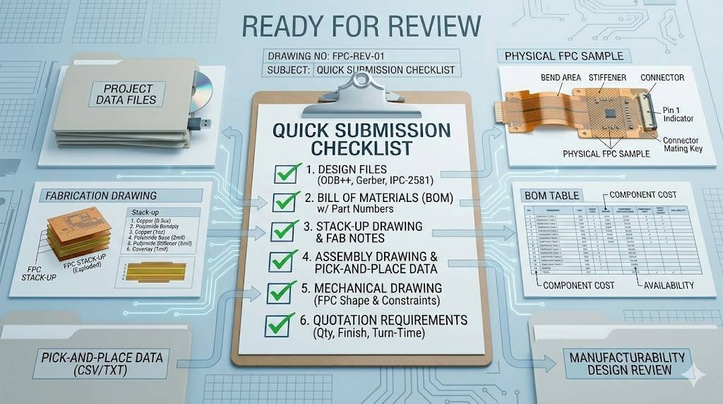
Quick Submission Checklist
Before requesting a flexible PCB assembly quote, make sure the package is complete, consistent, and easy to review. A simple checklist can reduce delays and improve the chances of getting an accurate quote on the first pass.
- Gerber files are included and packed in one ZIP archive.
- The BOM includes manufacturer part numbers, quantities, reference designators, and any approved alternates or DNP parts.
- The pick-and-place or centroid file is included in a usable format with X-Y coordinates and rotation data.
- The assembly drawing clearly shows orientation, polarity, and special placement notes.
- Quantity and target lead time are clearly stated.
- Flex-specific requirements such as stack-up, bend areas, stiffeners, thickness, or connector constraints are documented.
- Testing and inspection expectations are included if they affect pricing or process planning.
- All files match the same revision and use clear file names.
- A short readme or note is added if the project has unusual handling or build conditions.
With this kind of submission package, the supplier can move from file review to quotation more quickly and with fewer assumptions. For buyers, that usually means fewer clarification emails, better pricing accuracy, and a smoother transition into engineering review and production planning.
FAQ
Yes. Gerber files are one of the core files used to review the board layout, layers, outline, and related manufacturing data for a quote.
Yes, if you are requesting an assembly quote. Suppliers typically need a BOM so they can identify components, check package information, and estimate sourcing cost accurately.
A pick-and-place file, sometimes called a CPL or PNP file, tells the assembler where each SMT component should be placed on the board. It usually includes component coordinates, rotation, and side-of-board data.
Sometimes, but an assembly drawing is still very helpful. It gives the supplier a visual reference for polarity, orientation, and special notes that may not be obvious from Gerber and placement data alone.
Helpful supporting files can include a mechanical drawing, stack-up details, fabrication notes, test requirements, and photos of the intended install area. These details can reduce back-and-forth and help the engineering team understand special flex requirements sooner.
For flexible PCB projects, it is helpful to include stack-up requirements, bend information, stiffener details, and any special assembly notes. These details can affect manufacturability, handling, and final pricing.
The usual best practice is to send the files as one organized ZIP package with matching revision information and clear file names. This makes it easier for the supplier to review one complete data set instead of piecing files together from multiple messages.
Sometimes a supplier can provide a preliminary quote with incomplete data, but the result is often less accurate. Missing files or unclear details usually lead to follow-up questions, revised pricing, or delays in review.