Table of Contents
Quick-turn flexible PCB assembly is one of the fastest ways to move from design to a working prototype, but speed depends on more than just production capacity. This guide is focused on prototype and low-volume orders, where lead time, MOQ, and DFM checks can make or break a quick-turn schedule.
If you are an engineer, buyer, or project manager, the key questions are usually straightforward: How fast can the board be built? How many units do you need to order? And what design issues could slow everything down before production even starts?
In the sections below, we’ll cover typical lead times, common MOQ patterns, the DFM checks that matter most for flexible circuits, and the files you should prepare before requesting a quote. The goal is to help you place a faster, cleaner order with fewer surprises along the way.
What Quick-Turn Flexible PCB Assembly Means
Quick-turn flexible PCB assembly is not just about moving faster on the production floor. It usually means compressing the whole workflow, from file review and DFM checking to sourcing, assembly, test, and shipment, so the board can move from design release to finished parts with fewer delays.
For prototype and low-volume orders, speed matters because every extra round of clarification can push the schedule back. That is why quick-turn flex projects usually depend on two things: clean input files and designs that are already close to manufacturable.
What makes a project “quick-turn”
A project becomes truly quick-turn when the design is ready to build with minimal back-and-forth. In practice, that means the BOM is complete, component substitutions are understood, the flex stackup is clear, and the DFM review does not uncover major redesign issues.
This is especially important in flexible circuits, where material choice, bend area layout, and stiffener usage can affect whether the order stays on schedule. If those details are vague, even a fast assembly line cannot prevent delay.
When quick-turn is realistic
Quick-turn works best for prototypes, engineering samples, and low-volume pilot runs. These jobs usually have simpler purchasing patterns and a shorter decision cycle, which makes them easier to move through fabrication and assembly quickly.
It is less realistic when the design is still changing, the BOM includes hard-to-source parts, or the flex construction needs extra engineering approval. In those cases, the schedule is often determined more by readiness than by factory capacity.
Why flex assembly is different from rigid PCB assembly
Flexible PCB assembly is more sensitive to handling, layout, and mechanical stress than standard rigid board assembly. Because the circuit must survive bending and often uses different support structures, the assembler has to check more design details before releasing the job.
That is also why quick-turn flex orders benefit so much from early DFM review. A design that looks fine in a schematic can still create problems in the flex area, the stiffener zone, or the component placement plan.
Typical Lead Time for Quick-Turn Orders
Lead time for quick-turn flexible PCB assembly is usually measured from the moment the design package is approved, not from the moment you first request a quote. In other words, the clock typically starts after the files, BOM, and DFM details are clear enough for the job to move forward.
For prototype and low-volume orders, the timeline is often shorter than in full production, but it still depends on several moving parts: file review, parts availability, fabrication, assembly, and test. If any one of those steps is delayed, the whole schedule can slip.

What the lead time usually includes
A quick-turn schedule is usually made up of several stages. First comes file review and DFM checking, then component confirmation and sourcing, followed by PCB fabrication, assembly, inspection, and shipping.
That is why “fast assembly” does not always mean “fast delivery.” If the BOM includes hard-to-find parts or the flex stackup needs extra clarification, the order may spend more time in review than on the production floor.
Typical lead time ranges
For prototype jobs, quick-turn assembly can sometimes be completed in just a few days, especially when the files are clean and the parts are readily available.
For low-volume orders, the timeline is often a little longer because sourcing, scheduling, and testing can introduce extra steps.
Instead of promising a fixed number, it is better to think in ranges:
- Prototype orders: shortest lead time, often the fastest path to build-ready boards.
- Low-volume pilot runs: moderate lead time, usually longer than prototype but still much faster than standard production.
- Production runs: longer lead time, especially when procurement and process controls are stricter.
| Order type | Typical lead time | Main delay risk | Best use case |
|---|---|---|---|
| Prototype | Fastest | Missing files or part availability | Engineering validation |
| Low-volume pilot run | Moderate | Sourcing and approval delays | Pre-production testing |
| Production run | Longer | Procurement and scheduling | Repeat builds |
What slows a quick-turn order down
The most common delay factors are easy to predict. Missing files, unclear assembly notes, part shortages, stiffener questions, and DFM issues in the flex area can all add days to the schedule.
Even when a vendor offers rush service, the project still has to be buildable. If the design needs redesign, or if the material stackup is not finalized, the factory may have to pause the order until those issues are resolved.
Why flexibility in sourcing matters
One of the best ways to keep lead time short is to stay flexible on approved substitutes. If the original part is unavailable, a pre-approved alternative can keep the job moving without waiting for another round of engineering review.
This matters even more in flex assembly, where design changes can affect mechanical behavior and reliability. A schedule that looks aggressive on paper can still work if the files are complete and the sourcing plan is realistic.
MOQ in Flexible PCB Assembly
MOQ in flexible PCB assembly is not always a fixed number. In many cases, it depends on how the parts are sourced, how the board is built, and how much setup is required before production can begin.
For prototype and low-volume orders, MOQ is often more flexible than people expect. Some suppliers can support very small quantities, while others set a minimum based on material usage, assembly setup, or sourcing efficiency.
What MOQ really means
In practice, MOQ usually reflects the point where a job becomes efficient enough for the factory to run. That may be measured by units, panels, or even by component sourcing requirements, depending on the project and the supplier.
For flex assembly, MOQ can also be influenced by the need for special handling, added stiffeners, or extra inspection steps. The more process-specific the job is, the more likely the minimum order level will be shaped by production complexity rather than by the board count alone.
Why prototype orders are often smaller
Prototype orders are usually the easiest to keep small because the goal is validation, not volume. At this stage, the customer is often testing fit, function, and reliability before committing to a larger run.
That is why many flex assembly services are willing to accept very low quantities for prototypes, especially when the design files are complete and the parts are available. The tradeoff is that the per-unit cost may be higher than in a larger production run.
What affects MOQ
Several factors can raise or lower MOQ. Parts availability, package type, assembly setup, flex material choice, and special process requirements all play a role.
A few of the most common drivers are:
- Component sourcing constraints, especially for hard-to-find parts.
- Special flex construction, such as stiffeners or layered stackups.
- Setup effort for SMT, inspection, and testing.
- Ordering efficiency, which becomes more important as quantity increases.
How to think about MOQ strategically
Instead of asking only “What is the minimum number of pieces?”, it is often better to ask “What is the smallest quantity that still makes this build efficient and reliable?” That framing gives you a more realistic answer and helps you plan for cost, timing, and design risk at the same time.
If your goal is to validate a design quickly, a lower MOQ may be more valuable than a cheaper unit price. If your goal is to prepare for production, it may make more sense to step up from prototype quantities to a pilot run that better reflects final manufacturing conditions.
| Order stage | Typical MOQ pattern | Main driver | Best use case |
|---|---|---|---|
| Prototype | Very low or flexible | Validation and testing | First build |
| Low-volume pilot run | Moderate | Sourcing and setup efficiency | Pre-production |
| Production run | Higher | Cost efficiency and repeatability | Ongoing supply |
DFM Checks That Matter Most
DFM is where a quick-turn flex project either stays on schedule or starts to slip. Even if the parts are available and the factory is ready, a flexible PCB still needs to be checked for layout, material, and assembly details that can affect manufacturability.
For flexible circuits, DFM matters even more than in many rigid board projects because the board has to work electrically and mechanically at the same time. A design that looks fine on screen can still create problems once bending, stiffening, soldering, and handling are added into the process.
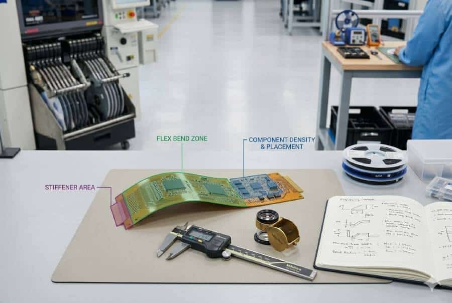
Bend radius and flex zones
Bend radius is one of the first things to check in a flex design. If the bend area is too tight or the routing is too aggressive, the circuit may become unreliable or difficult to build consistently.
The safest approach is to make sure the flex zone is clearly defined and that critical copper features are kept away from high-stress areas. This helps reduce mechanical stress during both assembly and final use.
Coverlay openings and solderability
Coverlay openings need to line up cleanly with the pads that will be soldered. If the openings are too small, too large, or poorly defined, the assembler may run into problems during reflow or hand soldering.
This is especially important in quick-turn jobs, where there is less time to correct avoidable file issues. A clear coverlay plan makes the assembly process smoother and lowers the chance of rework.
Stiffener placement
Stiffeners are often used to support connectors, component areas, or zones that need extra rigidity. But if the stiffener location is unclear, or if its thickness and coverage are not well defined, it can create confusion during assembly and slow the order down.
For quick-turn projects, stiffeners should be specified as early as possible in the design package. The assembler needs to know where they go, what material they use, and how they interact with the surrounding components.
Component placement on flexible areas
Not every component belongs on a flexible section. Heavy parts, tall connectors, and components exposed to repeated stress are usually better placed in reinforced or rigid areas.
If components are placed too close to bend zones, the board may fail later in use or become difficult to assemble reliably. Good placement choices reduce both manufacturing risk and long-term reliability risk.
Stackup, material, and thickness clarity
A quick-turn order also depends on having a clear stackup and material definition. The assembler needs to know the layer count, copper thickness, flex material, coverlay details, and any reinforcement requirements before the job can move forward.
When these details are missing, even a simple order can get stuck in clarification. Clear construction notes help the manufacturer avoid guesswork and keep the schedule moving.
Common DFM Risks in Flex Assembly
| DFM item | Why it matters | What to check | Delay risk |
|---|---|---|---|
| Bend radius | Affects reliability and manufacturability | Flex zone definition and routing | Medium to high |
| Coverlay openings | Affects solderability | Pad exposure and alignment | Medium |
| Stiffeners | Affects support and assembly flow | Location, thickness, material | Medium |
| Component placement | Affects mechanical stress | Distance from bend zones | Medium to high |
| Stackup clarity | Affects build readiness | Materials and thickness notes | High |
How to Avoid Delays Before You Quote
The fastest way to avoid delays in a quick-turn flex project is to make the quote package as complete as possible before you send it out. When the manufacturer receives clear files and clear requirements, the review process moves faster and the risk of back-and-forth drops significantly.
This matters even more for flexible PCB assembly because the design often depends on details that are easy to overlook, such as stiffeners, bend zones, coverlay openings, and component placement. If those details are not defined early, the order can slow down before it ever reaches production.
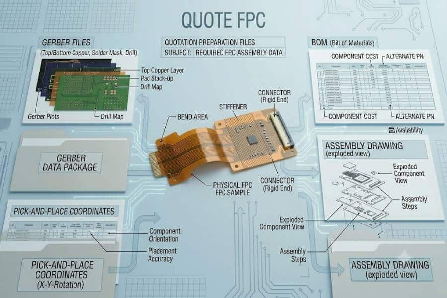
Prepare a complete file package
A good quote package should include the basic manufacturing files as well as the assembly instructions. At minimum, that usually means Gerbers, BOM, pick-and-place data, assembly drawings, and any notes that explain special flex requirements.
The more complete the package, the less likely the assembler is to pause and ask for clarification. For quick-turn work, that difference can save real time.
Lock down part availability early
Component sourcing is one of the biggest causes of schedule slips. If the BOM includes parts with long lead times or uncertain availability, the assembly start date may move even when the board files are ready.
When possible, it helps to confirm substitutions in advance. Approved alternates can keep the project moving if the primary part is unavailable, which is especially useful for prototype and low-volume orders.
Clarify all flex-specific details
Flex orders should never rely on assumptions. The assembler needs to know exactly where the flex zones are, how stiffeners should be applied, and what construction details matter for the final build.
If those details are buried in a comment or left out of the drawing, the quote process often slows down. Clear notes make it much easier for the manufacturer to review the job and commit to a realistic schedule.
Ask the right questions before release
It is smart to ask a few direct questions before approving a quick-turn job. For example: When does the lead time start? Is the MOQ based on units, panels, or sourcing? Are any DFM issues likely to affect the schedule?
These questions help you spot hidden delays before they happen. They also make it easier to compare suppliers on a like-for-like basis instead of relying on vague time estimates.
Keep the first build simple
If speed is the top priority, the first build should be as straightforward as possible. A simpler prototype is easier to quote, easier to source, and easier to assemble than a highly customized flex design.
That does not mean the design should be incomplete. It simply means that the fewer unresolved variables you have, the more realistic a fast turnaround becomes.
Before-Quote Checklist for Quick-Turn Flex Orders
| Item | Why it matters | Risk if missing |
|---|---|---|
| Gerbers | Defines the board geometry | Quote delay |
| BOM | Confirms parts and sourcing | Schedule slip |
| Pick-and-place file | Supports assembly setup | Placement errors |
| Assembly drawing | Shows instructions and notes | Misinterpretation |
| Flex notes | Clarifies bend, stiffener, coverlay details | DFM review delay |
FAQ
Quick-turn flexible PCB assembly can be very fast when the files are complete, the parts are available, and the design is already close to build-ready. In practice, the final schedule depends on file approval, sourcing, fabrication, assembly, and test rather than on assembly alone.
There is no single MOQ for every flex project, because the minimum often depends on sourcing efficiency, setup effort, and build complexity. Prototype orders are usually more flexible, while pilot runs and production jobs often follow different quantity rules.
At minimum, you should prepare Gerbers, BOM, pick-and-place data, assembly drawings, and any flex-specific notes such as stiffener or coverlay requirements. A complete file package makes the quote process faster and reduces the chance of delays.
The most common delays usually come from bend radius problems, unclear stiffener requirements, coverlay opening issues, component placement in flex zones, and incomplete stackup information. These items matter because flexible boards have to meet both electrical and mechanical requirements.
Yes, that is one of the most common ways to use quick-turn flex assembly. Many teams start with prototype or low-volume orders first, then move to a larger run after they confirm fit, function, and reliability.
Not necessarily, but a faster schedule usually leaves less room for ambiguity. If the files are clear and the design is ready, quick-turn can still be very reliable; the real risk comes from missing information or unresolved DFM issues.
Conclusion
Quick-turn flexible PCB assembly works best when the design is ready, the parts are available, and the DFM details are clear. If you can control lead time, MOQ, and flex-specific design risks before release, you give the project a much better chance of staying on schedule.
If you are planning a prototype or low-volume build, the next step is to prepare the quote package and confirm the key manufacturing details early. That usually saves time, reduces back-and-forth, and makes the entire build process much more predictable.