Table of Contents
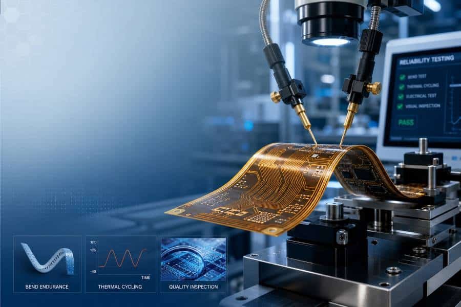
Flexible PCBs are widely used in products that must be thin, lightweight, and able to move, fold, or fit into compact spaces. But unlike rigid boards, their performance depends heavily on how well they can withstand bending, thermal stress, humidity, vibration, and long-term electrical use. That is why flexible PCB reliability testing is not just a quality control step — it is a critical part of verifying whether a design can survive in real-world applications.
In this article, we will explain the key standards and test methods used to evaluate flexible PCB reliability, including IPC-related requirements, bend cycle testing, peel strength testing, thermal cycling, and environmental stress tests. We will also look at the most common failure modes and the design factors that have the greatest impact on long-term durability, so you can better understand how to improve product reliability from the start.
Why Flexible PCB Reliability Testing Matters
Flexible PCBs are valued for their ability to save space, reduce weight, and fit into compact electronic assemblies, but those same advantages also create unique reliability risks. In real-world use, flex circuits are often exposed to repeated bending, thermal cycling, humidity, vibration, and mechanical stress, which can lead to conductor fatigue, delamination, cracked traces, or insulation failure if the design and materials are not properly validated.
That is why reliability testing is essential. It helps manufacturers verify whether a flexible PCB can survive its intended operating environment, and it gives engineers objective data to improve material selection, stack-up design, bend area layout, and process control before mass production begins.
For high-reliability applications such as automotive electronics, medical devices, industrial equipment, wearables, and aerospace systems, this step becomes even more important because a field failure can cause product downtime, costly rework, or safety risks. Standards such as IPC-6013 help define qualification and performance expectations for flexible and rigid-flex boards, while related IPC test methods support evaluation of electrical and mechanical durability.
Reliable testing also helps bridge the gap between design intent and real performance. A flex PCB may look acceptable in CAD or pass basic electrical checks, but still fail after repeated motion or environmental stress if the bend radius is too tight, copper routing is too aggressive, or the material system is not suited to the application.
From a manufacturing and sourcing perspective, reliability testing is also a quality assurance tool. It allows buyers to compare suppliers more confidently, helps reduce the risk of hidden defects, and provides evidence that the board has been evaluated against meaningful criteria rather than only visual inspection or simple continuity testing.
Key Standards for Flexible PCB Reliability
Flexible PCB reliability is usually evaluated against a combination of design, qualification, and test-method standards rather than a single document. Among the most important references are IPC-6013, which defines qualification and performance requirements for flexible and rigid-flex printed boards, and IPC-2223, which provides design guidance for flexible and rigid-flex circuits.
IPC-6013 is especially important because it helps establish what “acceptable” performance looks like for different classes of flex circuits. In practice, this means manufacturers and customers can align on reliability expectations before production starts, which is critical when the board will be used in applications where failure is not acceptable.
IPC-2223 plays a different but equally important role. It focuses on design rules and layout considerations that strongly influence reliability, such as bend area design, material transitions, routing strategy, and structural reinforcement around critical sections.
For actual test execution, IPC-TM-650 is one of the most commonly referenced method libraries. It includes procedures used to evaluate flexural endurance, peel strength, thermal shock, HiPot, impedance, and other reliability-related characteristics, giving engineers a repeatable way to measure whether a flexible PCB meets the intended requirements.
It is also important to note that many projects are not governed by IPC standards alone. Depending on the industry and end-use environment, customers may require additional qualification criteria, internal reliability specifications, or high-reliability class targets such as IPC Class 3 for demanding applications.
For this reason, flexible PCB reliability should always be defined at two levels: the design standard level and the test/acceptance level. When those two levels are aligned early, the result is fewer surprises in prototyping, better production consistency, and a lower risk of field failure.
Common Flexible PCB Reliability Tests
Flexible PCB reliability is usually verified through a combination of mechanical, thermal, environmental, and electrical tests. The exact test plan depends on the application, but the goal is always the same: confirm that the board can maintain electrical performance and structural integrity under real operating conditions.
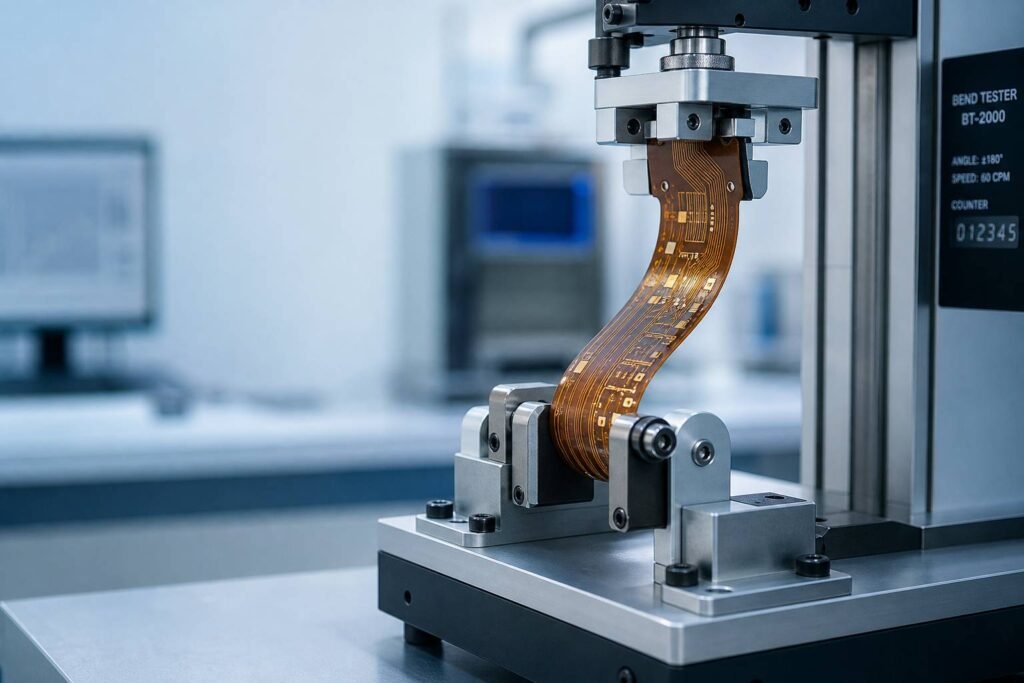
- Bend Cycle / Dynamic Flex Testing
Dynamic flex testing is one of the most important evaluations for flexible circuits. In this test, the board is repeatedly bent over a defined radius and cycle count to measure how long it can survive before conductor fatigue, cracking, or discontinuity occurs. - Peel Strength Testing
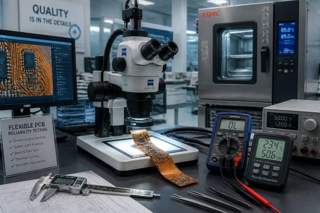
Peel strength testing measures the bond strength between the copper foil and the flexible dielectric material. This test is important because weak adhesion can lead to lifting, delamination, or loss of conductor integrity during manufacturing or field use. - Thermal Cycling and Thermal Shock
Thermal cycling and thermal shock tests expose the flex PCB to repeated temperature changes to evaluate material stability, expansion mismatch, and resistance to delamination or cracking. These tests are especially important for products used in automotive, industrial, and outdoor environments where temperature swings are common. - Humidity and Moisture Resistance Testing
Humidity-related tests check whether the flexible PCB can withstand moisture absorption and damp environments without corrosion, insulation failure, or electrical leakage. This is critical for electronics used in humid climates, sealed enclosures, or applications exposed to condensation. - Electrical Continuity and Insulation Tests
Electrical tests verify that traces remain open-free and short-free after mechanical or environmental stress. HiPot, insulation resistance, and continuity checks are often used to confirm that the board still meets its electrical requirements after reliability testing. - Vibration and Mechanical Shock Testing
Vibration and shock testing are used when the flex PCB will operate in moving equipment, transportation systems, or other mechanically demanding environments. These tests help identify weak routing areas, poor support structures, or stress concentration points that could fail during service.
In practice, a good reliability plan does not rely on only one test. Instead, it combines bend testing, peel strength, thermal stress, moisture exposure, and electrical verification to create a more complete picture of how the flexible PCB will perform over time.
How Test Results Are Evaluated
Evaluating flexible PCB test results is not just about checking whether the board still works after a test. The real goal is to determine whether the circuit has maintained electrical integrity, mechanical stability, and acceptable performance under the conditions it is expected to face in actual use.
The most common evaluation method is pass/fail criteria. For some tests, a simple result is enough: the board either survives the required number of flex cycles, passes electrical continuity, or shows no visible damage. For more demanding projects, results may also include logged measurements, tighter tolerances, or zero-defect requirements.
Typical Failure Modes
When a flexible PCB fails reliability testing, the issue is often not random. Common failure modes include conductor cracking, trace fracture, delamination, copper lifting, insulation breakdown, and loss of continuity in bend-sensitive areas.
These failures usually point to a specific design or material weakness, such as an undersized bend radius, poor copper routing, stress concentration near a stiffener, or a stack-up that cannot handle thermal expansion and mechanical movement.
What Good Results Look Like
A good result means more than “the board still powers on.” It means the flexible PCB remains electrically stable, shows no visible structural damage, and continues to meet the intended performance requirements after repeated stress or environmental exposure.
For example, after bend cycle testing, the board should still maintain continuity without intermittent opens. After thermal or humidity testing, it should show no delamination, corrosion, or insulation failure. After peel strength testing, the copper bond should remain strong enough to support the product’s expected service life.
Why Application Context Matters
Test results must always be judged against the real application, not just a generic benchmark. A flexible PCB used in a wearable device, for example, may need very different acceptance criteria than one used in an industrial controller or automotive subsystem.
That is why reliability evaluation should connect the test method to the product’s actual stress profile. If the board will flex thousands of times in service, then dynamic flex performance matters most. If it will face heat, moisture, or vibration, environmental durability becomes a bigger part of the evaluation.
From Test Data to Design Improvement
The most valuable part of reliability evaluation is not simply accepting or rejecting the board. It is using the result to improve the next design iteration by adjusting routing, material selection, bend radius, stack-up balance, or reinforcement strategy.
In other words, test results become most useful when they are treated as engineering feedback, not just quality paperwork. That approach helps reduce field failures and makes the final flex PCB much more dependable in production.
Factors That Affect Flex PCB Reliability
Flexible PCB reliability is strongly influenced by the way the circuit is designed, the materials that are selected, and how the board will be used in the final product. In most cases, failures are not caused by one single issue, but by a combination of mechanical stress, thermal expansion, material fatigue, and layout decisions that concentrate strain in critical areas.
- Bend Radius and Flexing Style
Bend radius is one of the most important factors in flex PCB reliability because smaller bends create higher strain on copper traces and dielectric layers. Dynamic flex applications, where the board bends repeatedly, are far more demanding than static flex applications, where the board is bent only during installation. - Copper Thickness and Copper Type
Copper thickness has a direct impact on bend life. Thicker copper is generally stronger for current carrying, but it reduces flexibility; by contrast, rolled annealed copper is usually preferred in dynamic flex areas because it handles repeated movement better than standard electrodeposited copper. - Material Selection
The choice of base film, adhesive system, and dielectric structure also plays a major role in durability. Polyimide is widely used because it offers strong thermal stability and flexibility, while adhesiveless constructions often improve bend performance and high-temperature reliability by reducing internal interfaces that can fail under stress. - Coverlay, Adhesives, and Stiffeners
Coverlay and adhesive systems protect the flex circuit, but they also influence mechanical behavior and long-term fatigue resistance. Stiffeners are useful for reinforcing connector areas and component zones, yet poor stiffener placement or abrupt transitions near the flex section can create stress concentration and reduce reliability. - Routing, Vias, and Transition Zones
Trace routing is another major factor. Vias, sharp turns, crowded traces, and abrupt rigid-to-flex transitions can all create weak points where cracks or delamination may begin, which is why IPC-2223-based design discipline is so important for flex and rigid-flex boards. - Environmental and Mechanical Stress
Even a well-designed board can lose reliability if the operating environment is too harsh. Heat, humidity, vibration, and repeated shock can all accelerate fatigue or weaken adhesive bonds, especially when the flex circuit is used in automotive, industrial, or wearable products.
In short, flex PCB reliability is not determined by one material or one test. It comes from the balance between geometry, copper behavior, layer construction, and the real stress profile of the end application.
Best Practices for Designing Reliable Flexible PCBs
The best way to improve flexible PCB reliability is to design for durability from the beginning, rather than trying to fix problems after testing. In practice, that means choosing the right materials, controlling bend stress, keeping the layout clean in flex zones, and making sure the mechanical structure matches the real application.
- Use an Appropriate Bend Radius
One of the most effective ways to improve flex life is to keep the bend radius as large as the product allows. A larger bend radius reduces strain on the copper and dielectric layers, which lowers the risk of cracking, fatigue, and premature failure. - Separate Static and Dynamic Flex Areas
Not every flex circuit is meant to move the same way. Static flex designs only bend during installation, while dynamic flex designs bend repeatedly during operation, so the material choice, trace geometry, and reinforcement strategy should be matched to the expected motion profile. - Keep the Bend Zone Clean
The bend area should be free of vias, pads, abrupt trace width changes, and other features that create stress concentration. Traces in the flex region should be routed carefully so they do not become the first point of failure during repeated movement. - Choose the Right Materials
Material selection has a major effect on long-term reliability. Polyimide, coverlay, copper type, and adhesive system all influence flexibility, thermal resistance, and resistance to fatigue, so the material stack should be selected based on both the mechanical load and the operating environment. - Reinforce Critical Areas Properly
Stiffeners should be used where mechanical support is needed, such as connector regions or component mounting areas, but they should be placed carefully to avoid creating new stress points near the flex section. The goal is to support the board without reducing the flexibility where it is actually needed. - Plan the Stack-up and Routing Early
A reliable flex PCB usually starts with a well-structured stack-up and thoughtful trace routing. Symmetrical construction, proper conductor placement, and smooth transitions between rigid and flexible sections all help reduce mechanical stress and improve repeatable performance. - Design for the Real Environment
A flex PCB should always be designed around the conditions it will actually face, not just around ideal lab assumptions. If the board will experience heat, vibration, humidity, or repeated movement, those factors should shape the design rules from the beginning.
In short, the most reliable flexible PCB designs are the ones that combine sound mechanical planning, appropriate materials, and disciplined layout practices. When those elements are built into the design early, the chances of passing reliability testing and surviving long-term use increase significantly.
How JHYPCB Supports Reliability Validation
At JHYPCB, reliability validation starts long before mass production. Through early design review, material selection support, and manufacturing process control, JHYPCB helps customers reduce the risk of common flex PCB failures such as cracking, delamination, weak adhesion, and stress-related trace damage.
A reliable flex PCB is not built by testing alone — it is built by combining proper design rules with stable fabrication capability. That is why JHYPCB focuses on bend zone planning, stack-up review, stiffener placement, and other DFM considerations that influence long-term mechanical and electrical performance.
For prototype and new-product development projects, JHYPCB can support customers with fast-turn flex PCB prototyping and process feedback, which makes it easier to verify whether a design can meet its intended reliability targets before moving into volume production.
JHYPCB also supports quality inspection and testing according to customer requirements and IPC-based expectations, helping ensure that flexible PCBs are checked against the right acceptance criteria rather than only basic appearance or connectivity checks.
In practical terms, this means customers can work with JHYPCB to align the design, fabrication, and validation stages into one reliability-focused process. The result is better consistency, fewer unexpected failures, and stronger confidence in the final product’s performance in the field.
FAQ
There is no single test that fits every flex circuit, because the most important test depends on how the board will be used. For dynamic applications, bend cycle testing is usually the most critical, while thermal cycling, peel strength, or humidity testing may matter more for boards used in harsh environments.
IPC-6013 is the main qualification and performance standard for flexible and rigid-flex printed boards, while IPC-2223 provides design guidance and IPC-TM-650 contains many of the test methods used for evaluation.
The answer depends on the material system, stack-up, copper type, bend radius, and whether the circuit is designed for static or dynamic flexing. A well-designed flex PCB can survive many repeated cycles, but the real target should always be defined by the application’s motion profile and reliability requirements.
Yes. A flexible PCB can pass continuity and visual inspection on the bench and still fail later because of repeated bending, vibration, thermal stress, or moisture exposure. That is why mechanical and environmental reliability testing are essential, not optional.
The most common causes include too-small bend radius, poor trace routing in bend zones, vias placed in flexible areas, weak material selection, and stress concentration near stiffeners or rigid-to-flex transitions.
Material selection affects bend life, thermal stability, adhesion strength, and resistance to environmental stress. Choosing the right copper, coverlay, adhesive system, and base film is one of the fastest ways to improve long-term reliability.
JHYPCB supports reliability-focused flex PCB development through early design review, material selection guidance, fabrication process control, prototype support, and customer-specific testing requirements aligned with IPC-based expectations.
Conclusion
Flexible PCB reliability is achieved through a combination of proper design, the right materials, and the right validation strategy. Standards such as IPC-6013, IPC-2223, and IPC-TM-650 provide the framework, but real reliability depends on how well the board is engineered for bend stress, thermal exposure, moisture, vibration, and long-term electrical stability.
In other words, testing is not just about finding defects after fabrication — it is about preventing failures before a product reaches the field. When reliability requirements are defined early and verified through the right tests, manufacturers can improve product life, reduce risk, and deliver much more dependable flex PCB assemblies.
At JHYPCB, we support customers with reliability-focused flexible PCB manufacturing, from early design review and material selection to prototype validation and production quality control. If your application demands stable performance in a compact, dynamic, or harsh environment, the best results come from treating reliability as part of the design process from day one.