Aluminum vs Stainless Steel Stiffeners for Flex PCB: Thermal Management & Mechanical Strength

Discover the key differences between aluminum and stainless steel stiffeners for flexible PCBs. This guide covers thermal conductivity, mechanical strength, cost comparison, and real-world applications to help you make the right material choice for your FPC design.
Close-up of a flexible PCB showing aluminum and stainless steel stiffener zones side by side for thermal management and mechanical reinforcement

Table of Contents

When designing a flexible printed circuit (FPC), most engineers immediately think of FR4 or polyimide (PI) stiffeners — and for good reason. These traditional materials solve the vast majority of reinforcement needs in flex PCB applications, from SMT component support to ZIF connector thickening.

But what happens when your FPC design demands something more? When you need to dissipate significant heat from high-power LEDs, maximize rigidity in an ultra-thin stackup, or shield sensitive circuitry from electromagnetic interference? This is where metal stiffeners — specifically aluminum and stainless steel — become essential design tools that FR4 and PI simply cannot replace.

Metal stiffeners bring a fundamentally different set of properties to flexible circuit board design. With thermal conductivity reaching 205 W/m·K for aluminum — nearly 700 times higher than FR4 — they function not just as mechanical reinforcement, but as passive heat sinks that actively pull heat away from hot components. Meanwhile, stainless steel stiffeners deliver tensile strength of 520–720 MPa and can be manufactured as thin as 0.05mm, making them the go-to solution when every fraction of a millimeter counts in your stackup height.

However, choosing between aluminum and stainless steel is not simply a matter of preference. Each material excels in different scenarios, and using the wrong one can lead to thermal management failures, unexpected weight penalties, or even electrical shorts due to improper isolation design.

In this comprehensive guide, we break down everything you need to know about using aluminum stiffeners and stainless steel stiffeners for flexible PCBs, including:

  • Core material properties — thermal conductivity, mechanical strength, density, and available thickness ranges
  • Key advantages and limitations of each metal stiffener type
  • Head-to-head comparison across thermal management, mechanical strength, weight, cost, and manufacturability
  • Critical design considerations — electrical isolation requirements, adhesive selection, and bonding methods
  • Real-world application examples across automotive, LED lighting, aerospace, and consumer electronics

Whether you are a PCB design engineer selecting stiffener materials for a new FPC project, or a procurement manager evaluating cost-performance tradeoffs, this guide will give you the technical depth and practical decision framework needed to choose the right metal stiffener for your flexible circuit design.

Why Metal Stiffeners? Understanding the Unique Advantages of Aluminum and Stainless Steel

Most flexible PCB stiffener guides focus on FR4 and polyimide — and for many designs, those materials are perfectly adequate. FR4 delivers reliable rigidity at a low cost, while polyimide matches the thermal and flexural characteristics of the flex circuit substrate itself. But when your FPC design pushes beyond standard SMT reinforcement or ZIF connector thickening, engineers need to look harder at their stiffener material options.

This is where   — enter the picture. Unlike dielectric materials, metal stiffeners bring a set of properties that are fundamentally different from what FR4 or PI can offer.

What Makes Metal Stiffeners Different from FR4 and Polyimide?

Metal stiffeners are not just “stronger versions” of traditional stiffener materials. They operate on an entirely different set of engineering principles — both as mechanical components and as functional elements within the overall FPC system.

The four core differentiators are thermal conductivity, electrical conductivity, formability, and high-temperature stability. Understanding these properties is the first step to knowing when and why to choose aluminum or stainless steel over conventional materials.

Core Property Comparison Across Four Key Dimensions

1. Thermal Conductivity

This is the most significant advantage that sets metal stiffeners apart. Aluminum has a thermal conductivity of approximately 205 W/m·K, which is roughly 680 times higher than FR4 (~0.3 W/m·K) and orders of magnitude greater than polyimide. This means aluminum stiffeners can function as passive heat spreaders, pulling heat away from high-power components and distributing it across a larger area for dissipation.

Stainless steel, while less effective than aluminum with a thermal conductivity of roughly 15–20 W/m·K, still outperforms polymeric stiffener materials by a significant margin — typically 50 to 70 times better than FR4 by volume.

2. Electrical Conductivity

Both aluminum and stainless steel are electrically conductive, which introduces a critical design consideration that dielectric stiffeners do not have. This conductivity can be an advantage — enabling the stiffener to serve as a ground plane or EMI shield — but it also creates a mandatory requirement for electrical isolation between the metal stiffener and any nearby copper traces or pads.

3. Moldability and 3D Forming

Metal stiffeners can be stamped, bent, and formed into precise three-dimensional shapes. This capability is especially valuable in applications where the FPC must conform to a specific mechanical geometry — such as wrapping around a curved housing or folding into a multi-plane assembly. Aluminum, being softer and more ductile, is particularly well-suited for post-stiffener forming operations.

4. High-Temperature Stability

Metals maintain their mechanical integrity at temperatures where polymeric adhesives and substrates begin to degrade. Aluminum resists structural deterioration well beyond 200°C, and stainless steel performs reliably at even higher temperatures. This makes metal stiffeners a strong choice for applications that undergo thermal cycling or operate in high-temperature environments.

Complete Material Properties Comparison Table

The table below provides a side-by-side comparison of the four most common stiffener materials across all relevant engineering parameters.

PropertyFR4Polyimide (PI)AluminumStainless Steel
Thermal Conductivity (W/m·K)~0.3~0.1–0.2~205~15–20
Tensile Strength (MPa)~350–450~200–230~200–250520–720
Density (g/cm³)~1.8–2.0~1.42.77.9
Typical Thickness Range0.1–2.0 mm0.025–0.3 mm0.1–1.5 mm0.05–0.5 mm
Electrical ConductivityInsulatingInsulatingConductiveConductive
CTE (ppm/°C)~14–18~20–30~23~16–17
SolderableYesNoNoNo
Corrosion ResistanceMediumHighMedium (needs anodizing)Very High
3D FormabilityNoNoYesLimited
EMI ShieldingNoNoYesYes
Relative CostLowMediumMedium-HighHigh

Note: Values represent typical ranges. Actual specifications vary by supplier and grade.

Four flexible PCB stiffener materials comparison: FR4, polyimide, aluminum, and stainless steel side by side

Key Application Scenarios for Metal Stiffeners

Metal stiffeners are not a “better by default” choice — they solve specific engineering problems that dielectric materials simply cannot address. Here are the primary application scenarios where aluminum or stainless steel stiffeners become the correct design decision.

High-Power Thermal Management
When your FPC carries high-power components such as LED arrays, power MOSFETs, or driver ICs, heat buildup becomes a critical reliability concern. An aluminum stiffener placed behind the component zone acts as an integrated heat spreader, conducting heat laterally and reducing the peak temperature at the component-to-board interface. Automotive LED lighting FPCs — particularly headlamp and taillight applications — commonly use aluminum stiffeners for this exact reason.

Ultra-Thin Mechanical Reinforcement
When stackup height is strictly constrained — such as in slim consumer electronics or wearables — you may need maximum rigidity from the thinnest possible stiffener. Stainless steel at 0.05–0.1mm thickness can provide rigidity comparable to a 0.3–0.4mm FR4 stiffener while occupying a fraction of the vertical space.

EMI/RFI Shielding Requirements
In designs that must meet electromagnetic compatibility (EMC) standards — common in medical devices, automotive electronics, and aerospace applications — the conductive properties of metal stiffeners can be leveraged to provide additional shielding. When properly grounded, an aluminum or stainless steel stiffener can reduce EMI emissions and improve immunity to external interference.

3D Mechanical Integration
Some FPC applications require the board to be formed into a permanent three-dimensional shape as part of the final product assembly. Aluminum’s ductility allows the stiffener — and the attached FPC — to be bent or stamped into complex geometries, effectively turning the flex circuit into an integrated structural component of the device housing.

Harsh Environmental Conditions
Stainless steel stiffeners, with their exceptional corrosion resistance (including salt spray resistance exceeding 72 hours per standard testing), are ideal for applications exposed to moisture, chemicals, or outdoor environments — such as marine electronics, industrial sensors, or automotive under-hood modules.

When to Stick with FR4 or Polyimide Instead

It is equally important to know when metal stiffeners are NOT the right choice. In the following scenarios, traditional dielectric materials remain the better option:

  • Standard SMT component support — FR4 provides ample rigidity at a fraction of the cost
  • ZIF connector thickening — Polyimide can be laminated in layers to precisely match connector specifications
  • Cost-sensitive high-volume production — Metal stiffeners add significant material and fabrication costs
  • Designs requiring reflow solderability — Metal stiffeners cannot pass through reflow ovens on the same side as components
  • Applications where electrical isolation is a challenge — The added complexity of insulating a conductive stiffener may introduce more risk than it resolves

Understanding where metal stiffeners fit — and where they do not — is the foundation for making the right material decision. The next two chapters dive deep into aluminum stiffeners and stainless steel stiffeners individually, examining their properties, advantages, limitations, and real-world use cases.

Aluminum Stiffeners for Flex PCB

Aluminum is the most widely used metal stiffener material in flexible PCB applications. Its exceptional thermal conductivity, lightweight profile, and favorable cost-to-performance ratio make it the default choice whenever heat dissipation is a design priority. This chapter examines aluminum stiffeners in detail — from material specifications and available thicknesses to real-world applications and common design pitfalls.

Material Properties and Typical Specifications

Aluminum stiffeners for FPC applications are typically manufactured from 5052 aluminum alloy sheet — a non-heat-treatable alloy known for its excellent formability, moderate strength, and good corrosion resistance. The 5052 grade is preferred over other aluminum alloys because it can be stamped and formed without cracking, while maintaining structural integrity in thin gauges.

Key material properties of 5052 aluminum stiffeners:

PropertyValue
Alloy Grade5052-H32 (most common)
Thermal Conductivity~200–205 W/m·K
Density2.68 g/cm³
Tensile Strength~215–255 MPa
Yield Strength~160–195 MPa
Elongation at Break~12–25%
Melting Point~600–650°C
CTE~23 ppm/°C

Available thickness options vary by manufacturer, but standard ranges typically include:

CategoryThicknesses
Standard Thicknesses0.20mm, 0.25mm, 0.30mm, 0.35mm, 0.40mm, 0.50mm
Extended Range0.15mm, 0.80mm, 1.00mm, 1.50mm
Minimum Available~0.10mm (custom)
Maximum Available~1.50mm (custom)

Surface treatments commonly offered include anodizing (Type II or Type III) for improved corrosion resistance and wear durability, and conductive coatings for applications where the stiffener doubles as a shielding or grounding layer.

Core Advantages of Aluminum Stiffeners

Aluminum stiffeners offer a combination of benefits that makes them difficult to replace in many flex PCB designs. The following four advantages explain why aluminum remains the most popular metal stiffener material.

1. Exceptional Thermal Conductivity for Heat Dissipation

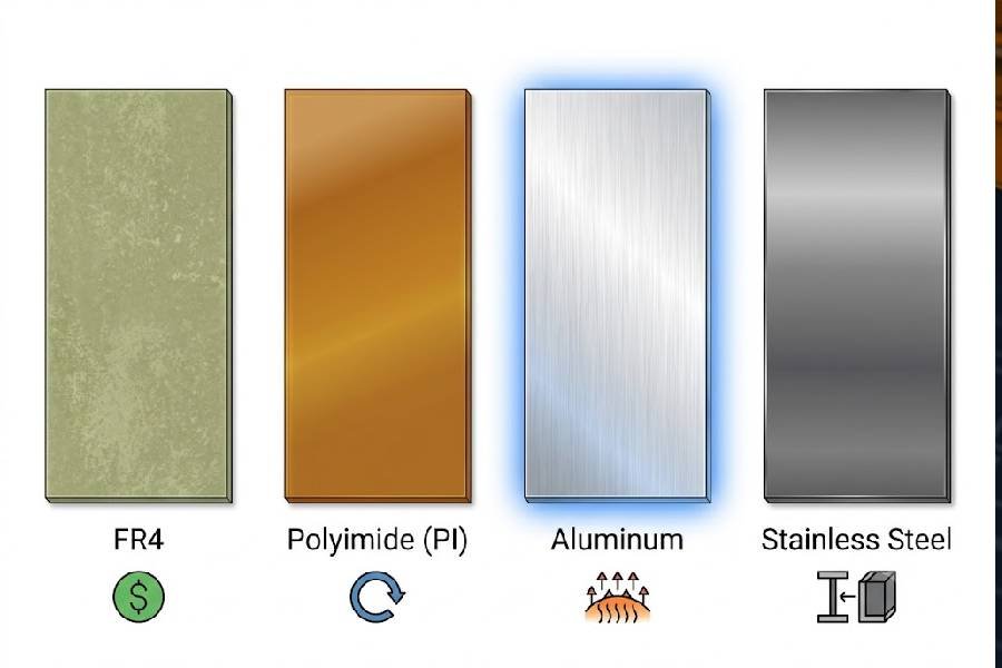
This is the defining advantage of aluminum stiffeners. At approximately 200–205 W/m·K, aluminum conducts heat roughly 680 times more efficiently than FR4. When placed behind a heat-generating component such as a power LED, MOSFET, or driver IC, the aluminum stiffener acts as an integrated heat spreader — drawing heat away from the component pad area and distributing it laterally across the stiffener surface, where it can dissipate into the surrounding air or device enclosure.

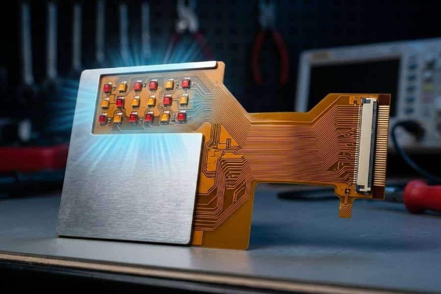
This thermal management function is so valuable that in some automotive LED FPC designs, the aluminum stiffener covers nearly the entire board surface, effectively turning the flexible circuit into a self-contained thermal management system.

2. Lightweight — 30% Lighter Than Stainless Steel

With a density of 2.68 g/cm³, aluminum is significantly lighter than stainless steel (7.9 g/cm³) while delivering comparable mechanical rigidity at reasonable thicknesses. This weight advantage is critical in portable and wearable electronics, where every gram counts. For projects with weight constraints — such as handheld medical devices, drone-mounted sensors, or head-worn displays — aluminum stiffeners deliver the mechanical support needed without the mass penalty of stainless steel.

3. Excellent 3D Formability and Customization

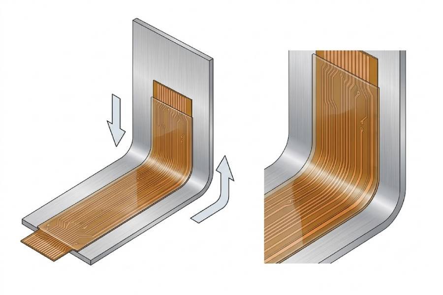
Aluminum is highly ductile and can be stamped, bent, and formed into complex three-dimensional shapes without cracking or losing structural integrity. This enables a wide range of manufacturing and assembly possibilities:

  • Post-stiffener forming: The FPC with attached stiffener can be bent to a specific angle or radius to fit within a device housing
  • Integration as part of the enclosure: The stiffener itself can become a structural component, reducing the need for separate mechanical brackets or housings
  • Custom hole patterns and contours: Stiffeners can be die-cut with precision openings for connectors, fasteners, or other mechanical features

Aluminum stiffener 3D forming demonstration on flexible PCB showing bendability and shape customization

4. Favorable Cost Structure for Medium to High Volumes

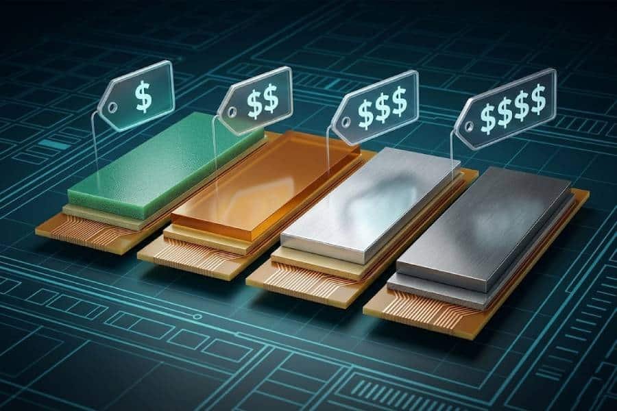
Aluminum stiffeners cost more than FR4 or polyimide stiffeners —typically 3 to 5 times higher per unit — but they remain significantly more affordable than stainless steel alternatives. For design teams weighing heat dissipation requirements against budget constraints, aluminum offers the most practical thermal management solution in the metal stiffener category. In high-volume production runs, the per-unit cost premium becomes negligible compared to the reliability gains from improved thermal performance.

Limitations and Design Challenges of Aluminum Stiffeners

Despite its advantages, aluminum is not a universal stiffener material. Understanding its limitations is essential for avoiding costly redesigns or field failures.

1. Electrical Conductivity Requires Strict Isolation

Because aluminum is electrically conductive, any contact between the stiffener and exposed copper traces, pads, or vias can cause a short circuit. This necessitates the use of insulating adhesive layers between the FPC and the stiffener — typically a polyimide film-backed PSA or a thermally conductive but electrically insulating adhesive.

Additionally, the edges of the aluminum stiffener must be carefully finished to prevent burrs or sharp edges that could cut through the insulation layer. Designers must ensure a minimum clearance — typically 0.5–1.0mm beyond component footprints — between the stiffener edge and any conductive circuit features.

2. Moderate Temperature Resistance Compared to Stainless Steel

While aluminum does not melt until approximately 600°C, its mechanical properties begin to degrade at temperatures above 150–180°C. This makes aluminum less suitable than stainless steel for applications that experience sustained high-temperature operation or repeated thermal cycling above 150°C. In environments where both high heat and high rigidity are required simultaneously, stainless steel may be the more reliable choice despite its lower thermal conductivity.

3. Adhesive Bonding Challenges

The naturally occurring oxide layer on aluminum surfaces can interfere with adhesive bonding, particularly with standard pressure-sensitive adhesives (PSA). Oxide layer thickness, surface contamination, and environmental exposure all affect bond reliability over time. For critical applications, surface preparation techniques such as chemical cleaning, mechanical abrasion, or plasma treatment should be evaluated before finalizing the adhesive selection.

4. Cannot Pass Through Reflow Soldering

Like all metal stiffeners, aluminum cannot be placed on the same side of the FPC that will undergo reflow soldering. The aluminum stiffener — along with its adhesive layer — is not designed to withstand the temperature profile of a standard SMT reflow process (typically peaking at 240–260°C for lead-free solder). This means aluminum stiffeners must be applied as a secondary process step after SMT assembly, adding both cost and lead time to the manufacturing workflow.

Typical Applications and Industry Examples

Aluminum stiffeners are most frequently chosen in applications where heat dissipation is a primary concern. Below are the most common use cases.

Automotive LED Lighting

In automotive headlamp and taillight modules, high-power LED arrays generate significant heat within a confined space. Aluminum stiffeners placed behind the LED zone act as integrated heat spreaders, drawing heat away from individual LED packages and distributing it across a larger surface area. The stiffener also provides mechanical support against vibration and thermal cycling — both critical requirements in automotive applications.

Aluminum stiffener applied to automotive LED taillight flexible PCB for heat dissipation and mechanical support

Power Electronics and Motor Drive FPCs

Flex circuits used in motor drive modules, power converters, and battery management systems often carry power MOSFETs and driver ICs that generate substantial heat. An aluminum stiffener positioned behind the power component area helps maintain junction temperatures within safe limits while providing the necessary rigidity for reliable solder joint integrity.

High-Power LED Strip and Display Applications

Flexible LED strips for architectural lighting, display backlighting, and signage commonly use aluminum stiffeners to manage heat build-up along the strip. The aluminum base both dissipates heat and provides the flat, rigid surface needed for precision LED placement during automated assembly.

Portable Medical and Consumer Electronics

In handheld medical devices, portable monitors, and wearable health sensors, aluminum stiffeners provide localized reinforcement around connector and component areas while keeping overall device weight within acceptable limits. The combination of light weight and thermal performance makes aluminum particularly attractive in battery-powered devices where heat buildup can affect both component reliability and battery life.

Stainless Steel Stiffeners for Flex PCB

When mechanical strength, ultra-thin profile, and environmental durability are the top priorities in a flexible PCB design, stainless steel stiffeners emerge as the superior metal option. While aluminum dominates thermal management applications, stainless steel fills a different — and equally critical — niche. This chapter provides a comprehensive examination of stainless steel stiffeners, including material grades, key properties, design advantages, limitations, and real-world use cases.

Material Properties and Typical Specifications

Stiffeners for flexible circuits are predominantly manufactured using austenitic stainless steel, with 301, 304, and 316 grades being the most common choices across the FPC industry.

301 stainless steel offers the highest strength and work-hardening rate, making it suitable for applications that require maximum stiffness in the thinnest possible gauge. 304 stainless steel — the most widely available grade — provides an excellent balance of strength, formability, and corrosion resistance for general-purpose stiffener use. 316 stainless steel, with its added molybdenum content, is reserved for the most corrosive environments, such as marine or chemical processing applications.

Key material properties of common stainless steel stiffener grades:

Property301 Stainless Steel304 Stainless Steel316 Stainless Steel
Thermal Conductivity~15–16 W/m·K~16–17 W/m·K~16 W/m·K
Density7.9 g/cm³7.9 g/cm³8.0 g/cm³
Tensile Strength520–860 MPa520–720 MPa480–620 MPa
Yield Strength~350 MPa~205 MPa~170 MPa
Elongation at Break~40–60%~40–45%~40–45%
CTE~16 ppm/°C~17 ppm/°C~16 ppm/°C
Corrosion ResistanceGoodVery GoodExcellent
Salt Spray Resistance~72+ hours~72–100+ hours~200+ hours

Available thickness ranges for stainless steel stiffeners:

CategoryThicknesses
Standard Thicknesses0.10mm, 0.15mm, 0.20mm, 0.25mm, 0.30mm
Extended Range0.05mm, 0.35mm, 0.40mm, 0.50mm
Minimum Available~0.05mm (custom)
Maximum Available~0.50mm (custom)

The ability to manufacture stainless steel stiffeners as thin as 0.05mm is a key differentiator — this is roughly one-quarter the minimum practical thickness of an FR4 stiffener and enables stiffener integration in the most space-constrained designs.

Core Advantages of Stainless Steel Stiffeners

Stainless steel stiffeners are selected not for thermal performance but for their mechanical and environmental characteristics. The following advantages explain why engineers choose stainless steel over both aluminum and traditional dielectric materials.

1. Extremely High Rigidity and Tensile Strength

With tensile strength ranging from 520 to 860 MPa, stainless steel delivers roughly double the tensile strength of aluminum and significantly exceeds FR4. The modulus of elasticity for stainless steel (~193 GPa) also contributes to superior stiffness per unit thickness — meaning a 0.1mm stainless steel stiffener can provide rigidity comparable to a 0.3–0.4mm FR4 stiffener. This makes stainless steel the go-to choice when a designer needs maximum mechanical reinforcement in the absolute minimum stackup height.

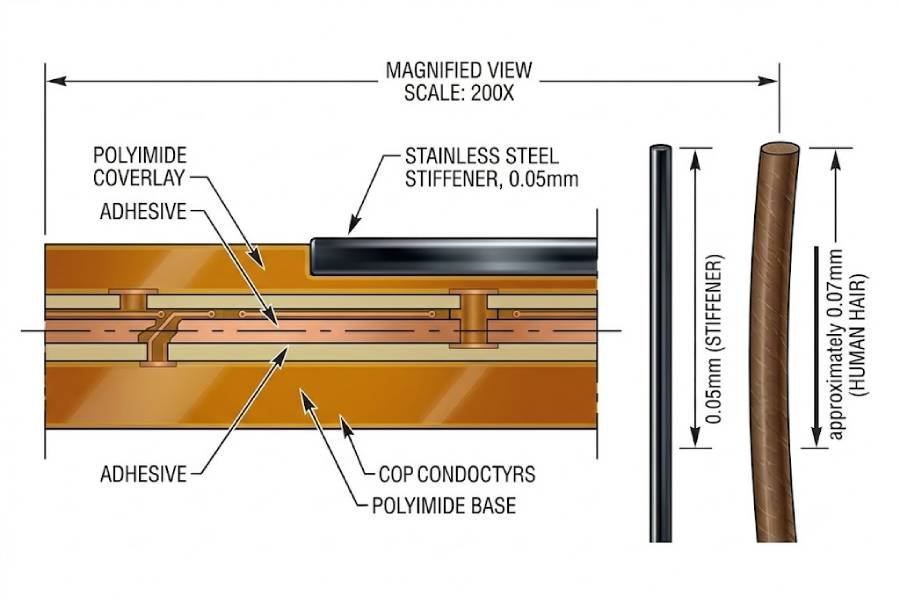
2. Ultra-Thin Profile — Down to 0.05mm

The ability to be manufactured and handled at 0.05mm thickness sets stainless steel apart from all other stiffener materials. At this thickness, the stiffener adds negligible height to the overall stackup — a critical advantage in ultra-slim portable electronics, implantable medical devices, and other applications where every 0.1mm of vertical space is at a premium.

Cross-section view of a 0.05mm ultra-thin stainless steel stiffener on flexible PCB compared to human hair scale

3. Superior Corrosion and Environmental Resistance

Stainless steel — particularly the 304 and 316 grades — offers outstanding resistance to corrosion, oxidation, and chemical exposure:

  • Moisture resistance: Unlike FR4, which can absorb moisture and swell, stainless steel remains dimensionally stable in humid environments
  • Salt spray resistance: 304 grade stainless steel typically passes 72–100+ hours of salt spray testing; 316 grade exceeds 200+ hours
  • Chemical stability: Resistant to most industrial chemicals, including acids and solvents
  • Temperature stability: Maintains mechanical properties across a wide temperature range (from below -50°C to well above 400°C)

This environmental resilience makes stainless steel stiffeners ideal for applications in harsh or uncontrolled environments — industrial equipment, outdoor infrastructure, oil and gas sensors, and marine electronics.

4. Effective EMI and RFI Shielding

The electrical conductivity of stainless steel enables it to serve as a passive electromagnetic shielding layer when properly grounded. While not as effective as copper or aluminum for EMI shielding on a per-thickness basis, stainless steel stiffeners still provide measurable shielding benefit — particularly in the low to mid-frequency range. This dual function (mechanical reinforcement + EMI shielding) can eliminate the need for a separate shielding layer in some designs, reducing overall complexity and cost.

5. Excellent Vibration and Shock Resistance

Stainless steel’s high yield strength and fatigue resistance make it particularly well-suited for applications subject to repeated mechanical shock or vibration. In automotive, aerospace, and industrial equipment markets, where FPCs experience years of vibration cycling, a stainless steel stiffener helps prevent solder joint fatigue failure and maintains connector alignment integrity.

Limitations and Design Challenges of Stainless Steel Stiffeners

Despite its mechanical and environmental superiority, stainless steel stiffeners come with tradeoffs that must be evaluated during the design phase.

1. Significantly Heavier — Nearly 3x Aluminum

With a density of 7.9 g/cm³, stainless steel is approximately 2.9 times heavier than aluminum. In weight-sensitive applications — portable handheld devices, wearables, aerospace systems — this mass penalty can become a decisive factor. Designers should always evaluate whether the additional rigidity of stainless steel justifies the weight increase for a given application.

2. Lower Thermal Conductivity

At approximately 15–20 W/m·K, stainless steel’s thermal conductivity is roughly one-tenth that of aluminum — making it a poor choice for thermal management applications. If heat dissipation is a primary design concern, aluminum stiffeners are the better option. Stainless steel can even act as a minor thermal barrier, trapping heat in localized areas if placed directly beneath high-power components.

3. Higher Cost and Longer Lead Times

Stainless steel stiffeners carry the highest per-unit cost among all metal stiffener options — typically $1.50–$3.00 per piece at volume compared to $1.00–$2.50 for aluminum. The material is also more difficult to cut and form than aluminum, often requiring custom stamping dies or laser-cutting equipment. These factors combine to increase both unit cost and lead time, particularly for non-standard sizes or small prototype runs.

4. Limited 3D Formability

Unlike aluminum, which can be easily bent or deep-drawn into complex shapes, stainless steel has significantly lower ductility — especially in the higher-strength 301 grade. While light forming operations (gentle bends and shallow flanges) are feasible, deep forming or complex contours are difficult and may require intermediate annealing steps. For designs requiring significant post-stiffener forming, aluminum remains the preferred choice.

5. Same Electrical Isolation Requirements as Aluminum

As a conductive material, stainless steel stiffeners carry the same mandatory requirement for electrical isolation as aluminum. Every exposed conductive circuit feature on the FPC must be protected from contact with the stiffener through insulating adhesive layers and proper edge clearance design. This adds both material cost and design complexity.

Typical Applications and Industry Examples

Stainless steel stiffeners are most frequently selected in applications where mechanical performance and environmental durability outweigh thermal considerations. The following use cases represent the most common scenarios.

Space-Constrained High-Rigidity Support

In ultra-slim consumer electronics such as smartphones, tablets, and thin laptops, the internal volume budget for flex stiffeners is extremely limited. A 0.05–0.1mm stainless steel stiffener can reinforce connector zones and component areas without exceeding height constraints — a feat impossible with FR4 or aluminum at equivalent rigidity levels.

Harsh Environment and Industrial Applications

FPCs used in factory automation equipment, oil and gas instrumentation, marine sensors, and outdoor communication infrastructure are routinely exposed to moisture, salt spray, chemicals, and extreme temperature cycling. Stainless steel stiffeners — particularly 316 grade — provide the corrosion resistance and dimensional stability these environments demand.

Automotive Connector and Sensor FPCs

Within automotive engine compartments and chassis assemblies, flex circuits must withstand prolonged exposure to heat, oil, and vibration. Stainless steel stiffeners at connector zones prevent connector loosening from vibration, while the material’s corrosion resistance ensures long-term reliability over the vehicle’s service life.

Medical and Aerospace Electronics

Sterilizable medical instruments, implantable devices, and aerospace avionics often require FPCs that can endure rigorous environmental testing. Stainless steel’s biocompatibility (particularly 316L grade) and ability to pass stringent shock and vibration specifications make it a natural fit for these highly regulated applications.

EMI-Sensitive Instrumentation and Communication

In RF and microwave circuits, medical imaging equipment, and precision measurement instruments, electromagnetic interference must be carefully managed. A grounded stainless steel stiffener can provide supplementary shielding in localized areas, reducing both emissions and susceptibility without requiring a full copper-based shielding layer.

Head-to-Head Comparison: Aluminum vs Stainless Steel

Now that we have examined aluminum and stainless steel stiffeners individually, this chapter provides a direct, side-by-side comparison across the most relevant engineering dimensions. The goal is to provide a clear decision framework that helps designers quickly identify which material best fits their specific FPC project requirements.

Complete Property Comparison Table

The following table summarizes the core engineering properties of both materials for quick reference.

PropertyAluminum StiffenerStainless Steel Stiffener
Primary Alloy Grades5052-H32301, 304, 316
Thermal Conductivity~200–205 W/m·K~15–20 W/m·K
Tensile Strength200–255 MPa480–860 MPa
Yield Strength~160–195 MPa~170–350 MPa
Density2.68 g/cm³7.9 g/cm³
Standard Thickness Range0.20–0.50 mm0.10–0.30 mm
Minimum Thickness~0.10 mm~0.05 mm
Maximum Thickness~1.50 mm~0.50 mm
Electrical ConductivityConductiveConductive
CTE~23 ppm/°C~16–17 ppm/°C
Corrosion ResistanceMedium (requires anodizing)Very High (304/316)
3D FormabilityExcellentLimited
EMI ShieldingYesYes
High-Temperature StabilityModerate (~150°C)Excellent (400°C+)
Relative Material CostMedium-HighHigh
Typical Lead TimeMediumMedium-High

Thermal Management Showdown

Thermal conductivity is the single most decisive factor when choosing between aluminum and stainless steel for FPC stiffeners. The difference is not marginal — it is profound.

Aluminum at approximately 205 W/m·K conducts heat roughly 10 to 13 times more effectively than stainless steel at 15–20 W/m·K. To put this in perspective, a 0.3mm aluminum stiffener behind a 1W high-power LED can reduce the LED junction temperature by 8–15°C compared to an FR4 stiffener of the same dimensions. The same LED paired with a stainless steel stiffener would see a negligible thermal improvement — approximately 1–2°C over FR4.

This gap explains why aluminum is overwhelmingly preferred for any application with meaningful heat dissipation requirements. Stainless steel stiffeners, while thermally superior to polymeric materials, should never be selected with thermal performance as a primary objective.

When to choose aluminum for thermal reasons:

  • LED lighting strips and automotive headlamps
  • Power MOSFET or driver IC heat spreading
  • High-power density component zones
  • Applications requiring passive thermal management without active cooling

When stainless steel is thermally acceptable:

  • Low-power analog or digital circuits with negligible heat generation
  • Situations where the FPC is mounted to an external heat sink or chassis
  • Designs where minimal stiffness — not thermal performance — is the goal

Mechanical Strength and Rigidity Battle

Mechanical strength is where stainless steel decisively outperforms aluminum. The comparison depends on how strength is measured.

From a purely tensile standpoint, stainless steel grades 301–304 deliver 520–860 MPa — roughly two to three times higher than aluminum’s 200–255 MPa. More importantly for stiffener design, the Young’s modulus of stainless steel (~193 GPa) is approximately three times that of aluminum (~70 GPa). This means that for the same stiffener thickness and geometry, a stainless steel stiffener will deflect roughly one-third as much under the same load.

However, this comparison must be normalized for thickness. A 0.3mm aluminum stiffener and a 0.1mm stainless steel stiffener may deliver comparable flexural rigidity in many practical FPC layouts — yet the aluminum version weighs less than half the amount. This trade-off between weight and stiffness is a key design decision point.

When to choose stainless steel for mechanical reasons:

  • Space-constrained designs where the stiffener thickness budget is extremely limited
  • Applications requiring maximum rigidity in the minimum possible profile
  • High-vibration environments where fatigue resistance is critical
  • Connector zones requiring high crush resistance

When aluminum provides sufficient mechanical support:

  • Standard SMT component reinforcement
  • LED strip or power electronics heat spreader applications
  • Designs where 0.25–0.5mm thickness is acceptable
  • Portable or weight-sensitive devices

Weight and Size Considerations

The density difference between the two materials is the single most impactful variable for portable, wearable, and aerospace applications.

MetricAluminumStainless Steel
Density2.68 g/cm³7.9 g/cm³
Weight ratio (same thickness)1.0x2.95x

A typical FPC stiffener measuring 50mm x 30mm x 0.3mm weighs approximately 1.2 grams in aluminum and 3.5 grams in stainless steel. For a device carrying ten such stiffeners, this difference accumulates to over 23 grams — a non-negligible margin in battery-powered handheld or head-worn devices.

Conversely, if a designer can substitute a 0.3mm aluminum stiffener with a 0.1mm stainless steel stiffener while achieving comparable rigidity, the weight difference narrows significantly. In such cases, the stiffener selection should be driven by other factors — thermal needs, corrosion resistance, or cost.

Cost and Lead Time Comparison

Cost is often a deciding factor — particularly in medium to high-volume production where per-unit savings compound dramatically.

Cost FactorAluminumStainless Steel
Material Cost per Unit (1000+ pcs)$1.00–$2.50$1.50–$3.00
Compared to FR4 Stiffener~3–5x~5–10x
Compared to Polyimide Stiffener~2–4x~3–6x
Tooling/Setup CostMediumMedium-High
Typical Lead Time (Prototype)5–7 days7–10 days
Typical Lead Time (Volume)10–15 days12–20 days

From a purely commercial standpoint, aluminum stiffeners are the more economical metal option for most production runs. Stainless steel becomes cost-competitive only when the application specifically demands its unique advantages — ultra-thin profile, maximum strength, or exceptional corrosion resistance — that cannot be achieved any other way.

Quick Decision Guide: Aluminum vs Stainless Steel

The following decision matrix provides a fast reference for selecting the right metal stiffener based on your primary design priority.

Primary Design PriorityChoose AluminumChoose Stainless Steel
Heat dissipation is criticalYes — Best thermal performanceNo — Only ~1/10th of aluminum
Must minimize stiffener thicknessNo — 0.1mm minimum practicalYes — Down to 0.05mm
Maximum rigidity is requiredNo — Lower yield strengthYes — 2–3x tensile strength
Harsh environment exposureNo — Requires anodizingYes — Superior corrosion resistance
Weight must be minimizedYes — 66% lighter than stainlessNo — Nearly 3x heavier
3D forming or bending requiredYes — Highly formableNo — Limited ductility
EMI shielding neededYesYes (both work)
Cost is a sensitive factorYes — Lower unit costNo — Higher material and tooling cost
High-temperature stability neededNo — Degrades ~150°CYes — Stable to 400°C+
Standard SMT reinforcementNo — Overkill, use FR4No — Overkill, use FR4

This decision framework covers the vast majority of practical stiffener material selection scenarios. The next chapter examines the critical design considerations — electrical isolation, adhesive bonding, and manufacturing compatibility — that apply to both aluminum and stainless steel stiffeners equally.

Critical Design Considerations When Using Metal Stiffeners

Selecting the right metal stiffener material — aluminum or stainless steel — is only the first step in the design process. The real engineering work begins when translating that material selection into a manufacturable, reliable flex PCB assembly. Metal stiffeners introduce several unique design challenges that do not exist with traditional dielectric stiffeners like FR4 and polyimide.

This chapter covers the critical considerations that every designer must address before committing a metal stiffener design to production. Ignoring these factors can lead to field failures, assembly yield losses, or costly redesigns.

Electrical Isolation — The Non-Negotiable Requirement

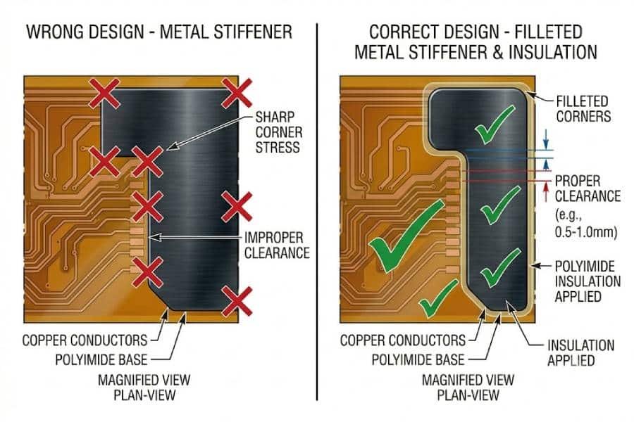
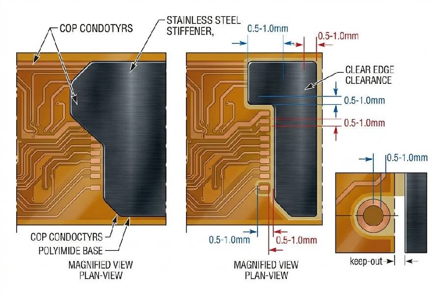
The most critical and non-negotiable design requirement for any metal stiffener is electrical isolation. Both aluminum and stainless steel are electrically conductive. Any direct contact between the stiffener and exposed copper circuitry — whether traces, pads, or vias — will cause an electrical short. This is a fundamental constraint that shapes every aspect of a metal stiffener design.

Why Isolation Matters

Unlike FR4 or polyimide stiffeners, which are inherently insulating, a metal stiffener becomes part of the electrical system the moment it touches copper. In high-density FPC layouts, even a small registration error during stiffener placement can allow a burr or edge to bridge two adjacent conductors. A micro-short between a power rail and signal trace can cause intermittent failures that are extremely difficult to diagnose in the field.

Diagram showing electrical isolation design for metal stiffener on flexible PCB with edge clearance to copper traces

How to Design for Proper Isolation

  • Insulating adhesive layer: Always use an electrically insulating adhesive between the metal stiffener and the FPC. Typical options include polyimide film-backed PSA or thermally cured dielectric adhesives. The adhesive must completely cover the stiffener-to-FPC interface with no gaps or pinholes.
  • Edge clearance rules: Maintain a minimum clearance of 0.5–1.0mm between the stiffener edge and any exposed copper feature (pads, traces, vias, or solder mask openings). For high-density designs with fine-pitch components, increase this clearance to 1.0–1.5mm to account for placement tolerance.
  • Burr and edge control: Specify deburred or rounded stiffener edges in your fabrication requirements. Sharp stamped edges can cut through the insulating adhesive layer over time, creating latent shorts. Many manufacturers offer radius-edged stiffeners or chamfered edges at minimal additional cost.
  • Via and pad protection: Do not allow metal stiffeners to overlap with vias or open pads. If the stiffener zone must extend near via areas, ensure the vias are fully covered by solder mask and the stiffener edge remains outside the solder mask opening by at least the minimum clearance distance.

Adhesive Selection and Bonding Methods

The adhesive layer between the metal stiffener and the FPC is not simply a mechanical joiner — it is a functional interface that must survive temperature cycles, environmental exposure, and mechanical stress throughout the product’s lifetime. The choice between pressure-sensitive adhesive (PSA) and thermal bonding methods has significant implications for both reliability and manufacturability.

PSA (Pressure-Sensitive Adhesive)

PSA-based bonding is the most common and economical approach for attaching metal stiffeners to FPCs. The adhesive layer is pre-applied to the stiffener surface, protected by a release liner, and bonded to the FPC through pressure during lamination.

Advantages of PSA:

  • Lower processing cost and complexity
  • No heat curing equipment required
  • Suitable for prototyping and short production runs
  • Faster turnaround time

Limitations of PSA:

  • Lower long-term bond strength compared to thermal bonding
  • Adhesive may soften or degrade under sustained heat exposure
  • Less reliable at temperatures above 85–100°C
  • Bond quality is sensitive to surface cleanliness and pressure uniformity

Thermal Bonding (Heat-Cured Adhesives)

Thermally cured adhesives offer superior bond strength and thermal stability, making them the preferred choice for demanding applications. The stiffener is typically laminated to the FPC under heat and pressure using a polyimide film or prepreg layer that cures into a permanent bond.

Advantages of Thermal Bonding:

  • Higher bond strength and peel resistance
  • Better performance under thermal cycling
  • Lower CTE mismatch stress over time
  • More reliable in high-temperature environments

Limitations of Thermal Bonding:

  • Higher processing cost due to lamination equipment and cycle time
  • Longer lead time for fabrication
  • May require multiple lamination cycles if stiffeners are needed on both sides of the FPC

Special Consideration for Aluminum Surfaces

Aluminum stiffeners present a unique bonding challenge: the naturally occurring surface oxide layer (Al2O3) reduces adhesive wetting and bond strength. For critical applications, the following surface preparation methods are recommended:

  • Chemical cleaning: Remove contaminants using solvent or alkaline cleaning prior to adhesive application
  • Mechanical abrasion: Light grit blasting increases surface roughness and adhesive contact area
  • Anodizing: Type II anodizing creates a controlled oxide layer that improves both corrosion resistance and adhesive adhesion
  • Plasma treatment: For high-reliability applications, plasma surface treatment can significantly improve bond reliability

Stainless steel stiffeners do not have the same oxide adhesion challenge, but their surfaces should still be cleaned of oils and fingerprints before bonding to ensure consistent results.

Thermal Expansion Mismatch and Stress Management

Both aluminum and stainless steel have coefficients of thermal expansion (CTE) that differ significantly from the polyimide flex substrate. This mismatch creates internal stresses during temperature cycling — a primary failure mechanism in metal stiffener applications.

CTE Values and Mismatch Analysis

MaterialCTE (ppm/°C)
Polyimide (FPC substrate)20–30
Aluminum~23
Stainless Steel (304/316)~16–17
FR4~14–18

Aluminum’s CTE (~23 ppm/°C) actually falls within the polyimide range, making it relatively benign in terms of thermal expansion mismatch. Stainless steel, at ~16–17 ppm/°C, creates a more significant CTE delta — approximately 5–10 ppm/°C lower than the FPC substrate. This differential can generate meaningful shear stress at the adhesive interface during thermal cycling, especially in designs with large stiffener surface areas.

Design Strategies to Minimize CTE-Induced Stress

  • Segment large stiffeners: Instead of a single large stiffener, consider splitting the stiffener into smaller discrete zones separated by flex regions. This reduces the accumulated expansion differential across each zone.
  • Use filleted or rounded stiffener corners: Sharp corners concentrate stress. Filleted corners (minimum 0.5mm radius) distribute thermal stress more evenly and reduce the risk of adhesive delamination or stiffener edge peeling.
  • Avoid placing stiffener edges near bend zones: Maintain a minimum separation of 1.5–3.0mm between the stiffener edge and any designated flex or bend area. CTE-induced stress at the stiffener edge can initiate cracks in the flex substrate if the stiffener is too close to a bend line.
  • Coordinate with your fabricator: Work with your FPC manufacturer early in the design process to validate the stiffener layout against their lamination process capabilities. Some fabricators can recommend optimal stiffener segmentation patterns based on their process experience.

Manufacturing and Assembly Compatibility

Metal stiffeners introduce additional processing steps that differ from standard FR4 or polyimide stiffener integration. Understanding these implications early prevents delays and cost overruns.

Post-SMT Stiffener Application

Like all metal stiffeners, aluminum and stainless steel stiffeners cannot be placed on the SMT assembly side of the FPC before reflow. The stiffener and its adhesive layer are not designed to withstand reflow temperature profiles (240–260°C peak for lead-free processes). This means:

  • Metal stiffeners are applied as a secondary process step after SMT assembly
  • This adds additional handling and alignment requirements
  • Prototype and small-batch lead times may be longer compared to all-PI or all-FR4 stiffener designs

Dual-Sided Stiffener Designs

When stiffeners are required on both sides of the FPC — for example, to support components on both top and bottom — additional lamination cycles are necessary. Each lamination cycle adds cost and increases the risk of registration errors. Designers should carefully evaluate whether dual-sided stiffeners are truly necessary or whether the design can be optimized to use stiffeners on a single side only.

Panelization and SMT Carrier Function

One of the less-known but highly valuable uses of metal stiffeners is as an SMT assembly carrier. By adding a larger aluminum or stainless steel stiffener to a small FPC array, the entire panel becomes rigid enough to run through automated SMT assembly equipment without requiring a separate fixture or pallet. This application — sometimes called a “stiffener carrier” or “process stiffener” — can reduce SMT setup costs and improve placement accuracy. The carrier stiffener is typically removed or left as part of the final assembly depending on the product requirements.

Common Metal Stiffener Design Mistakes to Avoid

Based on industry experience and manufacturer feedback, the following are the most common errors made when integrating aluminum or stainless steel stiffeners into FPC designs:

MistakeConsequencePrevention
Insufficient edge clearance near copper featuresElectrical shorts or latent failuresMaintain 0.5–1.5mm minimum clearance
Using standard PSA for high-temperature applicationsAdhesive degradation and delaminationSelect high-temp rated adhesive or thermal bond
Sharp stiffener cornersStress concentration and peelingUse filleted corners with 0.5mm+ radius
Stiffener edge too close to bend zoneSubstrate cracking at the edgeMaintain 1.5–3.0mm separation
Overlooking burr/edge qualityInsulation layer penetration and shortsSpecify deburred or chamfered edges
Specifying non-standard stiffener thicknessExtended lead time and higher costUse standard thicknesses when possible
Ignoring CTE mismatch in large stiffenersThermal cycling failuresSegment large stiffeners into smaller zones
Skipping surface treatment on aluminumPoor adhesive bonding reliabilityRequest cleaning, anodizing, or plasma treatment
metal stiffener design mistakes correct vs incorrect

FAQ: Common Questions About Aluminum and Stainless Steel Stiffeners

Choose aluminum stiffeners when thermal management is a priority — such as in high-power LED, power electronics, or automotive FPC applications. Aluminum's thermal conductivity (~205 W/m·K) vastly outperforms FR4 and polyimide, making it effective at pulling heat away from hot components.

Choose stainless steel stiffeners when you need maximum rigidity in the minimum thickness — particularly when your stackup height budget is extremely tight (under 0.15mm). Stainless steel's tensile strength (520-860 MPa) and ability to be manufactured down to 0.05mm make it irreplaceable for ultra-slim designs or applications exposed to harsh environments.

For standard SMT reinforcement, ZIF connector thickening, or cost-sensitive production, FR4 or polyimide remain the better choices.

Aluminum has a thermal conductivity of approximately 200–205 W/m·K, while stainless steel ranges from 15–20 W/m·K. This means aluminum conducts heat roughly 10 to 13 times more effectively than stainless steel.

To put this in practical terms: a 0.3mm aluminum stiffener behind a 1W power LED can reduce junction temperature by 8–15°C compared to FR4. A stainless steel stiffener of the same thickness would deliver a negligible improvement of only 1–2°C.

If heat dissipation is a meaningful part of your design problem, aluminum is the material choice. Stainless steel should never be selected for thermal reasons.

Yes, both aluminum and stainless steel stiffeners are electrically conductive and can provide electromagnetic interference (EMI) shielding when properly grounded. However, this benefit comes with important constraints:

  • The stiffener must be electrically isolated from the FPC circuitry via an insulating adhesive layer, yet connected to a ground point to function as a shield — a dual requirement that adds design complexity.
  • Shielding effectiveness depends on stiffener coverage area, grounding quality, and the frequency range of the interference.
  • For high-power shielding requirements, a dedicated copper layer or EMI shielding film may still outperform metal stiffeners.

EMI shielding should be considered a secondary benefit of metal stiffeners rather than the primary design driver.

Aluminum stiffeners are commonly available in the following standard thicknesses:

  • Standard: 0.20mm, 0.25mm, 0.30mm, 0.35mm, 0.40mm, 0.50mm
  • Extended: 0.15mm, 0.80mm, 1.00mm, 1.50mm

Stainless steel stiffeners are available in thinner gauges, with these common thicknesses:

  • Standard: 0.10mm, 0.15mm, 0.20mm, 0.25mm, 0.30mm
  • Extended: 0.05mm, 0.35mm, 0.40mm, 0.50mm

From a cost and lead time perspective, always prioritize standard thicknesses. Non-standard gauges require custom material sourcing, which increases both cost and delivery time.

No. Neither aluminum nor stainless steel stiffeners — nor the adhesive layers used to bond them — are designed to withstand the temperature profile of a standard SMT reflow process (typically peaking at 240–260°C for lead-free solder).

This means that metal stiffeners must be applied as a secondary process step after SMT assembly. This is an important manufacturing constraint that affects lead time and cost planning.

If your design requires stiffener coverage on the SMT assembly side, consider using FR4 or polyimide stiffeners in those specific areas instead, as they can withstand reflow temperatures.

Preventing electrical shorts requires a three-layer defense:

Insulating adhesive: Always use an electrically insulating adhesive layer (polyimide-backed PSA or dielectric adhesive) between the metal stiffener and the FPC. This is the primary isolation barrier.

Edge clearance: Maintain a minimum clearance of 0.5–1.0mm between the stiffener edge and any exposed copper feature (pads, traces, vias, or solder mask openings). For fine-pitch designs, increase this to 1.0–1.5mm.

Edge quality control: Specify deburred or radius-edged stiffeners. Sharp stamped edges can puncture the insulating adhesive over time, creating latent shorts that may not manifest until the product is in the field.

It depends on the application requirements:

PSA (Pressure-Sensitive Adhesive) is suitable for:

  • Standard-temperature applications (below 85°C)
  • Prototyping and short production runs
  • Cost-sensitive projects
  • Faster lead times

Thermal bonding (heat-cured adhesive) is preferred for:

  • Applications subject to thermal cycling
  • High-temperature environments (above 100°C)
  • High-reliability or safety-critical designs
  • Long-term bond strength requirements

For aluminum stiffeners specifically, ensure the adhesive is compatible with the aluminum oxide layer. Anodizing the aluminum surface prior to bonding significantly improves adhesion reliability.

Yes, significantly. At production volumes of 1,000+ pieces:

MaterialTypical Cost per UnitCompared to FR4
FR4$0.25–$0.60Reference
Aluminum$1.00–$2.50~3–5x FR4
Stainless Steel$1.50–$3.00~5–10x FR4

Both metal stiffeners are considerably more expensive than dielectric alternatives. The cost premium should always be justified by a clear functional requirement — thermal management, ultra-thin profile, or environmental durability — rather than selected as a general upgrade.

Yes, but with important manufacturing implications. When stiffeners are required on both sides of the FPC (for example, to support components on both top and bottom), the design requires multiple lamination cycles — one for each side.

Each additional lamination cycle adds:

  • Fabrication cost (typically $0.10–$0.30 per board)
  • Lead time (typically 2–3 additional days)
  • Potential for registration errors

Whenever possible, design the layout so that stiffeners can be applied to a single side only, or evaluate whether the bottom-side stiffener can be replaced with a smaller or lighter alternative.

Yes, and this is one of aluminum's key advantages over stainless steel. Aluminum 5052 alloy has excellent ductility and can be:

  • Bent to specific angles after being laminated to the FPC
  • Stamped into custom contours or hole patterns
  • Integrated as part of the device housing structure

This 3D formability is particularly valuable in applications where the flex circuit must conform to a curved or multi-plane enclosure — such as automotive interior lighting, wearables, or handheld medical devices. Stainless steel, by contrast, has limited formability and should not be used in designs requiring significant post-stiffener forming.

Stainless steel is decisively superior for harsh environment and outdoor applications. Its advantages include:

  • Excellent corrosion resistance — 304 grade passes 72+ hours of salt spray testing; 316 grade exceeds 200+ hours
  • Thermal stability from below -50°C to above 400°C without property degradation
  • Dimensional stability in high-humidity environments (unlike FR4, which absorbs moisture)
  • Chemical resistance to oils, industrial solvents, and marine environments

For applications such as industrial automation equipment, oil and gas instrumentation, marine electronics, or outdoor infrastructure, 304 or 316 stainless steel stiffeners are the recommended choice.

Use the following decision checklist:

Step 1: Is heat dissipation a primary concern?

  • Yes → Choose aluminum
  • No → Continue to Step 2

Step 2: Is maximum rigidity needed in under 0.15mm thickness?

  • Yes → Choose stainless steel
  • No → Continue to Step 3

Step 3: Will the FPC be exposed to harsh, corrosive, or outdoor environments?

  • Yes → Choose stainless steel
  • No → Continue to Step 4

Step 4: Does the stiffener need to be 3D formed or bent?

  • Yes → Choose aluminum
  • No → Continue to Step 5

Step 5: Are weight constraints critical?

  • Yes → Choose aluminum
  • No → Continue to Step 6

Step 6: Is this a standard SMT reinforcement or ZIF connector application?

  • Yes → Choose FR4 or polyimide
  • No → Re-evaluate your stiffener requirement; metal may still be necessary based on other factors

After following this checklist, if your answer is stainless steel at any step, verify whether aluminum can also satisfy the requirement at a lower cost — especially for thermal management or general mechanical support applications.

Conclusion

Aluminum and stainless steel stiffeners each solve specialized problems in flexible PCB design that traditional materials cannot address. Aluminum dominates thermal management applications with its exceptional 205 W/m·K thermal conductivity, while stainless steel excels where maximum rigidity, ultra-thin profiles, and environmental durability are required.

The right choice depends on your primary design driver: choose aluminum for heat dissipation, portability, and 3D forming needs; choose stainless steel for space-constrained rigidity, harsh environments, and high-vibration applications. For standard SMT reinforcement or ZIF connector applications, FR4 and polyimide remain the cost-effective choice.

Understanding these distinctions is essential for every FPC engineer — and makes the difference between a design that merely works and one that performs reliably over the product’s full lifecycle.

Ready to Discuss Your Flex PCB Stiffener Requirements?

At JHYPCB, we specialize in flexible PCB manufacturing with full support for custom stiffener integration — including aluminum, stainless steel, FR4, and polyimide materials. Our engineering team can help you optimize stiffener layout, material selection, and adhesive bonding for your specific application.

Explore Our Custom Flex PCB Services
Contact JHYPCB Engineering Team

Related Reading

About us

JHYPCB is a leading PCB prototyping, PCB manufacturing and assembly service provider in China, offering quick turn PCB prototyping, multi-layer PCB manufacturing and turnkey PCB assembly services.

Recent Posts

PCB assembly service
Scroll to Top