Table of Contents
Stiffeners are one of the most overlooked cost drivers in flex PCB design. Most engineers focus on layer count, material stack-up, and copper weight — but the stiffener choices buried in the fab notes can quietly add 20% to 200% to your per-unit cost.
Consider this: a standard FPC with a single FR4 stiffener costs approximately $0.25–$0.60 per piece at a 1,000-piece MOQ. The same design with a polyimide stiffener jumps to $0.80–$1.50 per piece, and switching to an aluminum stiffener adds another $1.00–$2.50 per unit. For a 5,000-piece production run, that’s the difference between a $1,625 BOM and a $7,500 BOM — purely from stiffener selection.
The data is clear but rarely consolidated:
- Material type alone can swing pricing by up to 10× (FR4 baseline vs. polyimide at 5–10× the material cost)
- Adhesive and lamination add $0.10–$0.40 per piece in hidden processing fees
- Each additional stiffener zone costs $0.10–$0.30 more per piece
- Regional sourcing matters: a stiffener PCB from China costs $0.30–$1.50/pc, versus $1.50–$5.00 from the USA and $2.00–$6.00 from Europe
- Tooling fees of $50–$150 per design are amortized only at volume, making small batches disproportionately expensive
This guide walks through every cost factor a PCB designer should evaluate before finalizing a flex stiffener design — from material selection (FR4, polyimide, aluminum, stainless steel) to adhesive strategy (PSA vs. thermal-set), panelization optimization, and seven actionable design rules that can reduce your stiffener cost by up to 40% without compromising mechanical reliability.
Whether you’re designing a consumer wearable, a medical device, or an industrial sensor, understanding how PCB stiffener costs stack up will help you make data-driven decisions that protect your BOM budget. By the end of this article, you’ll have a practical cost framework — with real pricing data from 2025–2026 market benchmarks — to optimize your flex PCB stiffener design from day one.
In this guide, you’ll learn:
- Why stiffeners add cost — and where those costs hide in your quote
- A material-by-material price analysis (FR4, polyimide, aluminum, stainless steel)
- How adhesive type, lamination cycles, and thickness affect per-piece pricing
- Panelization strategies that lower cost across the entire production panel
- 7 design rules to reduce stiffener cost by 20–40% without sacrificing performance
Why Stiffeners Add Cost to Flex PCBs
Stiffeners are mechanical reinforcements — but every stiffener you specify also adds layers of cost that most designers don’t see until the quote arrives. Unlike a standard rigid PCB, which is manufactured as a single continuous structure, a flex PCB with stiffeners introduces additional materials, bonding processes, and handling steps that compound across the entire production run.
The cost difference isn’t marginal. A typical hybrid (rigid-flex) PCB can cost approximately seven times that of the same design in a hard board, and two to three times an equivalent flex PCB with stiffeners. Understanding exactly where these costs come from — and how to control them — is essential for any designer working within a BOM budget.
The Five Hidden Cost Layers of a Stiffener
When you specify a stiffener in your flex PCB fab notes, five distinct cost layers are triggered simultaneously:
1. Material Cost — The Base Price of the Stiffener Itself
Every stiffener material has a per-square-foot raw material cost that forms the pricing baseline:
- FR4 (G10) epoxy: $2.00/sq. ft. — the industry standard reference point
- Polyimide film: $6.00–$10.00/sq. ft. for common thicknesses, up to $30–$60/sq. ft. for thicker constructions
- Prepreg (no-flow/low-flow): $1.50–$3.00/sq. ft.
This alone means polyimide stiffeners cost 3–5× more in raw material than FR4 before any processing is applied.
2. Fabrication Cost — Cutting the Stiffener to Shape
Once the raw material is sourced, it must be cut to match your flex circuit’s stiffener zone(s):
| Process | Cost Impact | Best For |
|---|---|---|
| Die-cutting | Lowest | High-volume, simple shapes (polyimide) |
| Laser cutting | Low–Medium | Low-volume, complex shapes (polyimide, FR4) |
| CNC milling / routing | Medium | FR4 stiffeners with drill holes |
| CNC profiling / V-grooves | +$0.10–$0.50/pc | Complex stepped profiles and cutouts |
FR4 stiffeners typically require both drilling (for through-hole components) and routing (for shape), while polyimide stiffeners can be die-cut or laser-cut — often at lower fabrication cost despite the higher material price.
3. Bonding/Adhesive Cost — Attaching the Stiffener
Stiffeners don’t float on a flex circuit — they must be bonded, and the adhesive choice adds a second cost dimension:
- Pressure-Sensitive Adhesive (PSA): Lower processing cost; no heat or pressure cycle required. However, PSA application can paradoxically add cost in some cases due to additional alignment and handling steps.
- Thermal-Set Adhesive (epoxy/acrylic): Preferred for permanent, high-reliability bonds; slightly less expensive than PSA on a per-piece basis in volume production.
- No-Flow Prepreg: Used when stiffeners are co-laminated into the flex stack-up; material cost is higher ($1.50–$3.00/sq. ft.) but eliminates a separate bonding step.
Adhesive and lamination combined typically add $0.10–$0.40 per piece to the final cost.
4. Lamination Cycle Cost — Extra Press Time
Thermal-set adhesives require the flex circuit to return to the lamination press for heat and pressure curing. Each additional lamination cycle adds both machine time and labor:
- Single-sided stiffener: 1 additional press cycle — baseline cost
- Dual-sided stiffeners (same area): May still require only 1 cycle if co-laminated
- Dual-sided stiffeners (different areas): Often requires 2+ cycles, significantly increasing cost and lead time
- Stepped or staggered profiles: Each unique thickness level may trigger additional processing
5. Assembly and Handling Cost — Placement, Registration, and Defect Risk
Stiffeners add handling complexity at the assembly stage:
- Placement accuracy: Stiffeners must be registered precisely to component keep-out zones — misregistration causes rework or scrap
- Handling time: Each stiffener zone adds manual or automated placement steps
- Defect risk: Air bubbles, adhesive voids, and misalignment all contribute to yield loss, which is factored into per-piece pricing
How Many Stiffeners Does Your Design Need?
The single biggest controllable cost variable in stiffener design is the number of zones. Each additional stiffener zone multiplies every cost layer above:
| Stiffener Configuration | Estimated Stiffener Sticker Price/pc |
|---|---|
| Single FR4 stiffener (1 zone) | $0.25–$0.60 (MOQ ≥ 1000 pcs) |
| Second FR4 stiffener added (+1 zone) | +$0.10–$0.30/pc |
| Single polyimide stiffener (1 zone) | $0.80–$1.50/pc |
| Dual-sided / stepped stiffener (custom) | $5.00–$9.00/pc |
For a 1,000-piece FPC with one FR4 stiffener at $0.35/pc, adding a second stiffener zone at +$0.20/pc increases total stiffener cost by 57% — from $350 to $550 for the production run.
Design takeaway: Before adding a second or third stiffener zone, ask whether components can be consolidated into a shared stiffener area. One consolidated zone is almost always cheaper than two scattered ones.
Stiffeners vs. Rigid-Flex: The Cost Reality
A common architecture decision in flex design is: should I use a flex PCB with stiffeners, or switch to a rigid-flex PCB?
From a per-piece cost standpoint, the answer is almost always clear — but the full picture requires system-level thinking.
Per-Piece Comparison (2025–2026 Market Data)
| Design Approach | Cost Per Piece (1000+ MOQ) | Lead Time | Process Complexity |
|---|---|---|---|
| FPC + single FR4 stiffener | $0.25–$0.60 | Short (5–10 days) | Low |
| FPC + single polyimide stiffener | $0.80–$1.50 | Short (5–10 days) | Low–Medium |
| FPC + aluminum stiffener | $1.25–$3.00 | Medium (10–15 days) | Medium |
| Rigid-flex PCB (2–4 layers) | $3.00–$6.50+ | Long (15–25 days) | High |
| Custom dual-sided/stepped design | $5.00–$9.00 | Long (15–25 days) | High |
The data shows that a rigid-flex PCB typically costs 2–7× more per piece than a comparable flex PCB with stiffeners.
Why is rigid-flex so much more expensive?
The raw material cost differential is significant. No-flow and low-flow prepreg — essential for rigid-flex construction — can cost up to 12× more than the high-flow prepreg used in standard rigid boards. Adhesiveless flex materials run $6.00–$10.00/sq. ft. versus ~$2.00/sq. ft. for equivalent rigid laminates — a 3–5× material cost increase.
When rigid-flex may justify the cost premium:
Despite higher per-piece pricing, a rigid-flex solution can be more cost-effective at the system level when it:
- Eliminates connectors and cable harnesses, reducing assembly parts and labor
- Improves high-speed signal integrity (no connector discontinuities)
- Reduces overall assembly steps and test time
- Enables higher component density in space-constrained enclosures
The rule of thumb: if your flex PCB with stiffeners requires multiple connectors, cable assemblies, or repeated flex cycles that create reliability risk, the system-level savings from rigid-flex may offset the 2–7× per-piece cost premium. For most standard applications — connectors, simple reinforcement, or thermal management — stiffeners on a flex PCB remain the more economical choice.
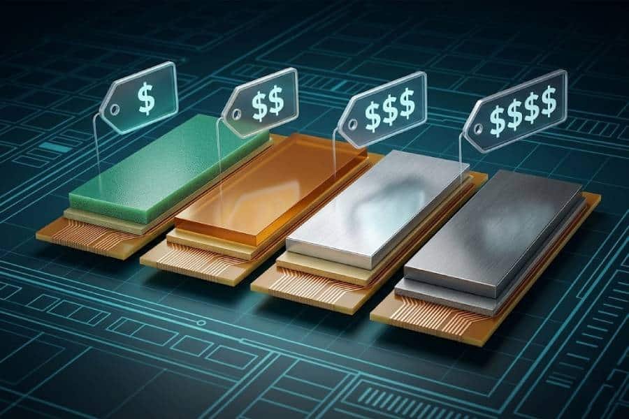
Stiffener Materials and Their True Cost Impact
Chapter 1 outlined the five hidden cost layers that every stiffener introduces — now let’s examine how each material choice affects those layers in practice. The material you specify in your fab notes is the single largest determiner of your stiffener’s per-piece cost, and the price spread between the cheapest and most expensive options is substantial.
As a reference point, FR4 (fiberglass-reinforced epoxy) remains the cost baseline across the industry. A standard flex PCB with a single FR4 stiffener typically costs $0.25–$0.60 per piece at a 1,000-piece MOQ. Every other material choice is priced relative to this benchmark.
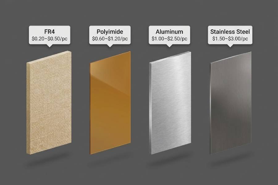
FR4 Stiffeners — The Budget Baseline
Sticker Price: $0.20–$0.50/pc (stiffener-only) | $0.25–$0.60/pc (full FPC + FR4 stiffener)
FR4 is the industry standard for flex PCB stiffening — and for good reason. It offers high mechanical strength (tensile strength ~310 MPa), supports plated through-holes, and is compatible with standard PCB fabrication processes at the lowest material cost of any common stiffener option.
Why FR4 is the default choice:
- Cost-effective: FR4 laminates cost approximately $2.00/sq. ft. — the baseline against which all other materials are compared
- Widely available: Standard thicknesses (0.008″–0.059″ / 0.2–1.5mm) are stocked by virtually every flex PCB fabricator
- PTH-compatible: Unlike polyimide, FR4 can be drilled and plated, making it ideal for supporting through-hole connectors
- Flat and rigid: Density of ~1.85 g/cm³ provides a stable assembly surface for SMT and mixed-technology components
FR4 cost caveats:
FR4 stiffeners require drilling (for through-holes) and routing (for shape), which adds fabrication time and cost compared to die-cut polyimide. The additional drill/route steps typically add $0.05–$0.15 per piece over die-cut-only alternatives. For high-volume designs with simple shapes, this is negligible — but for low-volume or prototype runs with complex cutouts, laser-cut FR4 can be more economical than traditional routing.
Best applications for FR4 stiffeners:
- SMT component support areas (the classic “rigid island”)
- Connector zones requiring PTH and mechanical stability
- General-purpose reinforcement where thickness is not constrained
- High-volume consumer electronics where cost-per-piece is paramount
Polyimide (PI) Stiffeners — Premium Flexibility at a Premium Price
Sticker Price: $0.60–$1.20/pc (stiffener-only) | $0.80–$1.50/pc (full FPC + PI stiffener)
Polyimide stiffeners — often sold under the Kapton brand — are the second-most common stiffener material and the go-to choice when thinness, flexibility, or high-temperature resistance is required. However, they come at a significant cost premium.
The cost math:
Polyimide film costs approximately $6.00–$10.00 per sq. ft. for popular thicknesses, and can run $30–$60 per sq. ft. for thicker constructions. Compared to FR4 at ~$2.00/sq. ft., this means polyimide raw material is 5–10× more expensive than FR4 before any processing is applied.
Despite the higher base material cost, polyimide stiffeners have a fabrication advantage: they are typically die-cut or laser-cut, eliminating the drill and routing operations that FR4 requires. For simple shapes in high volume, die-cutting can be faster and cheaper than FR4 routing — but the raw material cost difference almost always outweighs the fabrication savings.
Available thicknesses (standard): 0.001″ (25μm), 0.002″ (50μm), 0.003″ (75μm), 0.005″ (125μm)
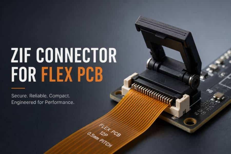
The ability to go as thin as 0.001″ makes polyimide the only practical choice for ZIF connector fingers and flex tails where every mil of thickness matters. Polyimide is also thermally stable up to 400°C and has a lower density (~1.42 g/cm³) than FR4, contributing to lighter overall assemblies.
Best applications for polyimide stiffeners:
- ZIF connector fingers requiring precise 0.3mm thickness specification
- Flex tails and insertion ends where partial flexibility is needed
- High-temperature environments (polyimide stable to 400°C vs. FR4 to ~130°C)
- Weight-sensitive applications (polyimide is ~23% lighter than FR4)
Design tip: For cost-sensitive designs, stick to standard polyimide thicknesses (0.002″, 0.003″, 0.005″). Non-standard thicknesses require custom ordering and can add 15–30% to material cost.
Aluminum Stiffeners — Thermal Management at a Mid-Range Cost
Sticker Price: $1.00–$2.50/pc additional over base flex price
Aluminum stiffeners are the preferred choice when thermal conductivity is a design requirement. With a thermal conductivity of approximately 200–205 W/m·K, aluminum serves as both a mechanical support and a heat spreader — making it ideal for high-power LED arrays, power electronics, and medical devices with thermal management needs.
Cost breakdown:
- Material cost: Aluminum is approximately 2–3× more expensive than FR4 in raw material cost.
- Processing cost: Aluminum cannot be drilled like FR4 or die-cut like polyimide. It requires CNC machining, waterjet cutting, or laser cutting, all of which are more expensive per-piece than standard flex PCB fabrication steps.
- Additional processing: Metal layers must be patterned and isolated to prevent electrical shorts, adding another process step.
Available thicknesses (standard): 0.1mm (4mil) to 0.5mm (20mil), with common sizes at 0.2mm, 0.25mm, 0.3mm, 0.35mm, 0.4mm, and 0.5mm.
The machined nature of aluminum stiffeners means longer lead times and often minimum order quantity (MOQ) requirements that don’t apply to FR4 or polyimide.
Best applications for aluminum stiffeners:
- High-power LED assemblies requiring heat dissipation
- Power electronics with thermal management requirements
- Medical devices where both rigidity and thermal conductivity are needed
- Applications where the stiffener doubles as a heat sink
Stainless Steel Stiffeners — Maximum Strength at a Premium
Sticker Price: $1.50–$3.00/pc (stiffener-only) | $5.00–$9.00/pc for custom dual-sided/stepped designs
Stainless steel stiffeners represent the highest-cost option in the standard stiffener material lineup. They are used almost exclusively when extreme rigidity is needed in an ultra-thin profile — situations where FR4 or aluminum at the same thickness simply cannot provide the required stiffness.
Cost and performance profile:
- Material cost: Among the most expensive stiffener materials, significantly above FR4, polyimide, and aluminum
- Mechanical strength: Stainless steel has a tensile strength of approximately 520 MPa — roughly 1.7× higher than FR4 (310 MPa) and far exceeding polyimide.
- Thickness advantage: Available in thicknesses as thin as 0.1mm (4mil) and 0.15mm (6mil) — thinner than what can be achieved with FR4 while maintaining superior rigidity.
- Processing: Like aluminum, stainless steel requires specialized CNC or waterjet machining, contributing to longer lead times and higher per-piece cost.
Corrosion resistance: Inherently resistant to corrosion, making it suitable for harsh-environment applications such as automotive sensors enduring -50°C to 150°C thermal cycles.
Available thicknesses (standard): 0.1mm (4mil), 0.15mm (6mil), 0.2mm (8mil)
Stainless steel stiffeners are rare in consumer electronics. They appear almost exclusively in medical, aerospace, and automotive applications where the performance requirements justify the cost premium. A stainless steel stiffener at 0.15mm thickness provides more rigidity than an FR4 stiffener at 0.5mm, making it the only viable option when both thinness and high stiffness are required simultaneously.
Best applications for stainless steel stiffeners:
- Implantable medical devices where thinness and biocompatibility are critical
- Wearable electronics with extreme space constraints
- High-stress mechanical environments (automotive sensors enduring -50°C to 150°C thermal cycles)
- Any application where maximum stiffness-to-thickness ratio is the overriding requirement
Material Cost Summary Table
| Material | Relative Cost (vs. FR4) | Est. Stiffener Cost/pc | Raw Material Cost/sq. ft. | Fabrication Process | Best For |
|---|---|---|---|---|---|
| FR4 | Baseline (1×) | $0.20–$0.50 | ~$2.00 | Drill + route | SMT support, PTH, high volume |
| Polyimide (PI) | 5–10× | $0.60–$1.20 | $6.00–$60.00 | Die/laser cut | ZIF fingers, thin profiles, high temp |
| Aluminum | 2–3× | $1.00–$2.50 additional | ~$5–$7/ft. foil | CNC/waterjet | Heat dissipation, thermal management |
| Stainless Steel | Highest | $1.50–$3.00 | Premium | CNC/waterjet | Max strength, ultra-thin, harsh env. |
Choose FR4 when:
- Your design has no thickness constraints below 0.008″ (0.2mm)
- You need plated through-holes (PTH) for connectors or components
- Cost-per-piece is a primary driver — FR4 is 5–10× cheaper than polyimide in raw material cost
- You’re producing in high volume, where small per-piece savings compound across thousands of units
- You’re supporting SMT components in a standard automated assembly process
- Your operating temperature stays below 130°C (FR4’s practical thermal limit)
Choose Polyimide when:
- Your ZIF connector specification requires a 0.3mm or thinner stiffened finger — polyimide is the only practical choice at 0.001″–0.005″ thickness
- You need a flex-to-rigid transition zone, where partial stiffening preserves some flexibility
- Operating temperature exceeds 130°C (polyimide is stable up to 400°C)
- Weight savings matter — polyimide at ~1.42 g/cm³ is approximately 23% lighter than FR4 at ~1.85 g/cm³
- Assembly rework savings offset the higher material cost — for example, a polyimide stiffener at +$0.50/pc may save $2.00/pc in assembly rework due to better ZIF compatibility
The most important insight: stiffener material choice should never be made on cost alone — but it should never be made without cost in mind.
A polyimide stiffener that costs $0.50 more per unit but prevents $2.00 in assembly rework is the smarter financial decision.
By the numbers: switching from FR4 to polyimide adds $0.20–$0.80 per piece in stiffener cost. But if that switch eliminates a $1.50 connector harness or reduces assembly cycle time by 15 seconds per board, the net effect is cost savings — not an increase.
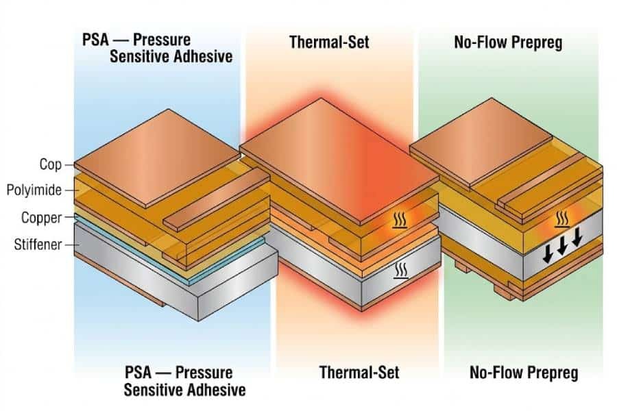
Hidden Costs: Adhesive and Lamination
Chapter 2 examined how material choice sets the stiffener’s cost baseline — but the adhesive system and lamination process can add another $0.10–$0.40 per piece on top of that baseline. This chapter breaks down adhesive types, lamination cycle impacts, and how thickness specifications influence the final price.
Adhesive Types and Their Price Impact
Every stiffener must be bonded to the flex circuit. The adhesive specifies both the mechanical bond quality and a significant portion of per-piece processing cost.
1. PSA (Pressure-Sensitive Adhesive): Pre-coated stiffener, no heat or pressure cycle needed. Lowest upfront material cost. Best for prototypes and low volume. Caveat: selective PSA with custom features requires laser cutting and tooling, which can reverse the cost advantage.
2. Thermal-Set Adhesive: Requires return to lamination press for heat and pressure curing. Adds $0.10–$0.40/pc over PSA. Permanent, high-strength bond. Best for high-volume production and harsh-environment applications.
3. No-Flow Prepreg: $1.50–$3.00/sq. ft. material cost. Integrated during initial layup — eliminates separate bonding step. Best for rigid-flex designs and high-reliability medical/aerospace applications.
Adhesive Type Cost Comparison Table:
| Type | Cost | Process | Bond | Best For |
|---|---|---|---|---|
| PSA | Lowest | Placement only | Moderate | Prototypes, low volume |
| Thermal-Set | +$0.10–$0.40/pc | Lamination press | High, permanent | High volume, harsh env. |
| No-Flow Prepreg | $1.50–$3.00/sq.ft. | Integrated layup | Highest | Rigid-flex, medical/aerospace |
Important nuance: While PSA has lower upfront cost, thermal-set adhesive is actually less expensive than PSA in some fabricator workflows. Sierra Circuits notes that thermal bonding adhesives are less expensive than PSAs for attaching coverlays — and the same relationship can apply to stiffener bonding. Always confirm with your specific fabricator.
Lamination Cycles — Where Costs Multiply
Each lamination cycle requires oven time, press time, and labor. More cycles = more cost.
Single-sided stiffener: One additional lamination pass. Cost impact: within $0.10–$0.40/pc adhesive range. Lead time: standard 5–10 days.
Dual-sided (same area): May be achievable in one cycle if both stiffeners co-laminated. If successful, cost remains similar to single-sided.
Dual-sided (different areas): Often requires two or more separate cycles. Each additional cycle adds $0.20–$0.50/pc and extends lead time by 5–10 days.
Stepped/staggered profiles: Most expensive configuration. Special placement zones or stepped profiles can add up to $0.50 per piece. Avoid unless functionally required.
Thickness Matters for Cost — Use Standard Sizes
Standard thicknesses are cheaper, faster, and more reliable than custom sizes.
Standard FR4: 0.008″, 0.010″, 0.015″, 0.020″, 0.031″, 0.047″, 0.062″
Standard Polyimide: 0.001″, 0.002″, 0.003″, 0.005″, 0.010″
Standard Aluminum: 0.2mm, 0.25mm, 0.3mm, 0.35mm, 0.4mm, 0.5mm
Standard Stainless Steel: 0.15mm, 0.2mm
Non-standard thicknesses require custom material sourcing, adding 15–30% to material cost and extending lead time.
Design rule: Before specifying a non-standard thickness, confirm whether a standard size can meet your mechanical requirements. Keeping all stiffeners the same thickness reduces processing time in fabrication.
Panelization Strategies for Cost Reduction
Panelization is one of the most significant — and most frequently misunderstood — cost levers in flex PCB with stiffener fabrication. A well-optimized panel layout can reduce your per-piece cost by 15–35% without changing any single component of your bill of materials. Conversely, a poor panelization strategy can silently add $0.15–$0.60 per piece in wasted material, depanelization labor, and yield loss.
Unlike rigid PCBs, which are typically v-scored or tab-routed from a standard 18×24″ panel, flex circuits with stiffeners introduce three competing constraints: the flex material must bend without cracking, the stiffener must remain flat and rigid, and the two materials respond to thermal and mechanical stress differently. Every panelization decision must account for all three.
Standard Panel Formats and Material Utilization Rates
The starting point for any cost-optimized panelization is understanding the raw sheet sizes your fabricator works with, and how much material actually ends up in the finished product versus the trim waste.
| Panel Format | Raw Sheet Size | Typical Material Utilization | Notes |
|---|---|---|---|
| Standard FR4 panel | 18×24 in (457×610 mm) | 65–85% | Most common; lowest waste for mid-size boards |
| Large format panel | 21×24 in (533×610 mm) | 75–90% | Available at some high-volume fabs; better for large layouts |
| Small batch panel | 12×18 in (305×457 mm) | 55–70% | Higher waste ratio; used for prototypes and low-MOQ |
| Roll-to-roll (flex only) | 13–24 in wide rolls | 80–92% | Best for high-volume flex; stiffener requires separate lamination |
| Custom panel (flex + stiffener stack) | Fab-defined | 60–80% | Laminate flex and stiffener together; reduces handling but limits panel optimization |
Data note: Material utilization rates reflect industry benchmarks from 2025–2026 for flex PCBs with surface-mounted stiffeners. Roll-to-roll figures exclude stiffener processing. Sources: Sienna Circuits PCB panelization guide, PCBWay manufacturing data, MacroFab DFM guidelines.
The key takeaway: if your board fits efficiently on a standard 18×24″ panel, your material waste will be in the 15–35% range — this is the baseline. Anything that forces your fabricator onto a smaller panel format, or that creates an awkward layout with large dead zones, will push waste higher and your per-piece cost up proportionally.
Stiffener Placement and Panel Layout Optimization
The position of the stiffener on the flex circuit directly determines how many boards you can fit on a single panel, how the panel must be routed, and how much handling and depanelization labor is required.
Symmetry matters. When stiffeners are placed asymmetrically on the flex substrate, the panel must accommodate the stiffener’s edge boundaries — not just the flex outline. This means a board that is 50mm × 30mm on the flex side might require a 60mm × 40mm panel footprint once the stiffener extends beyond the flex edge. Always specify whether the stiffener is co-planar (flush with the flex edge) or overlapping — overlapping stiffeners cost more in panel space.
Batch stiffener lamination before panel cutting. Some fabricators laminate the stiffener onto the flex after the panel has been depanelized into individual units — meaning the stiffener is applied one board at a time. This adds significant labor cost ($0.08–$0.20/pc). The more cost-effective approach is to laminate the stiffener onto the full panel first, then cut the boards. This requires advance planning in your Gerber data but can reduce per-piece stiffener cost by 20–40%.
Rail and tab routing. For flex PCB panels with stiffeners, depanelization typically uses tab routing rather than v-scoring (v-scoring is incompatible with flex substrates). Tab route panels require breakaway tabs at 5–10mm intervals around the board perimeter, which adds approximately 3–8mm of dead space per board. If you’re designing a panel of 10 small boards, those tabs collectively consume 10–15% of your panel area. Minimize tab count by maximizing board size and using mutual breakaway tabs between adjacent boards where possible.
Depanelization Method and Labor Cost Impact
Every panel must be separated into individual units. For flex circuits with stiffeners, this is a more complex operation than it is for standard rigid PCBs — and the method your fabricator uses has a direct per-piece cost impact.
| Depanelization Method | Cost Impact | Best For | Yield Risk |
|---|---|---|---|
| Tab route + hand break | $0.05–$0.12/pc | Prototypes, low volume | Low — manual control |
| Tab route + machine punch | $0.08–$0.18/pc | 500–5,000 pcs | Low–Medium — tooling wear |
| Laser depanelization | $0.15–$0.35/pc | High-precision flex, stepper motor connectors | Low — no mechanical stress |
| Router (CNC) depanel | $0.10–$0.22/pc | Medium volume, stiffener-inclusive panels | Medium — vibration risk to flex |
| Waterjet cutting | $0.20–$0.45/pc | Stainless steel stiffeners, complex outlines | Low — no heat or stress |
Data note: Cost figures represent 2025–2026 industry averages for flex PCB panels with surface-mounted stiffeners. Actual prices vary by fabricator and geographic region. Sources: Epec Engineered Technologies, All Flex PCB, VictoryPCB DFM guide, KINGSUN PCB.
For most production runs of 1,000+ pieces, tab route with machine punch or router depanelization offers the best cost-to-yield balance. Laser depanelization is reserved for applications where mechanical stress during separation is unacceptable — such as flex circuits with gold-plated edge fingers, fine-pitch ZIF connectors, or ceramic components near the board edge.
Design Rules That Reduce Stiffener Costs
Not all stiffener costs are determined during procurement — many are baked into the design long before the first quote is requested. This chapter identifies the specific design decisions that drive stiffener cost up or down, and provides a practical checklist of rules you can apply during schematic and layout to minimize downstream price impact.
The most important principle in this chapter: stiffener cost is additive, not multiplicative. Every design change that reduces stiffener area, simplifies geometry, or standardizes specifications compounds across the entire production run. On a 10,000-piece order, a $0.03 per-piece saving from a single design rule equals $300 in direct cost reduction — with zero change to your BOM or component selection.
Rule 1 — Minimize Stiffener Coverage to Functional Areas Only
The most direct lever you control as a designer is how much stiffener material you specify. Stiffener cost scales approximately linearly with area — double the stiffener size, and you roughly double the stiffener material cost (though panelization efficiency may partially offset this at higher volumes).
Design strategy: Instead of specifying a stiffener that covers the entire flex circuit, limit the stiffener footprint to only the areas that mechanically require reinforcement. Common functional areas include:
- Connector mounting zones (ZIF, board-to-board, FPC-to-PCB interfaces)
- Strain relief regions where the flex enters an enclosure
- Component mounting areas for surface-mount devices
- Fold line boundaries where the flex makes a controlled bend
A full-coverage stiffener on a 60mm × 40mm flex circuit might cost $0.45/pc. Restricting the stiffener to a 30mm × 15mm connector zone reduces material cost to approximately $0.15–$0.20/pc — a 55–67% stiffener cost reduction with identical mechanical performance where it matters.
Avoid “over-stiffening.” A common mistake in first-revision designs is to default to stiffener coverage that exceeds mechanical requirements by 2–3×. The marginal benefit of additional stiffening rapidly diminishes, while cost continues to scale. Use the stiffener only where the flex would otherwise flex during assembly, insertion, or service.
Data note: Connector-area-only stiffeners reduce stiffener material cost by 55–70% compared to full-coverage stiffeners for typical 40–80mm flex circuits. Source: Altium stiffener design guidelines, Epec application notes, KINGSUN PCB 2025–2026 fabrication benchmarks.
Rule 2 — Standardize Stiffener Thickness
Chapter 3 noted that non-standard stiffener thickness adds 15–30% to material cost. This rule explains how to apply that in practice.
Fabricators stock standard thicknesses of FR4, polyimide, and metal stiffener materials. When you specify a thickness that matches a stocked size, your stiffener is cut from available inventory. When you specify a non-standard thickness, the fabricator must source a custom sheet — and the cost of that sourcing, plus the minimum order quantity for the raw material, gets passed through to your per-piece price.
Standard FR4 thicknesses: 0.008″, 0.010″, 0.012″, 0.016″, 0.020″, 0.031″ (0.8mm), 0.047″ (1.2mm), 0.062″ (1.6mm)
Standard polyimide thicknesses: 0.001″ (25μm), 0.002″ (50μm), 0.003″ (75μm), 0.005″ (125μm), 0.0075″ (190μm), 0.010″ (250μm)
Standard metal stiffener thicknesses: 0.10mm, 0.15mm, 0.20mm, 0.30mm, 0.50mm
Design rule: Always specify a standard thickness first. Only deviate to a non-standard thickness if the standard option cannot meet your mechanical requirement — and if you do deviate, round up to the next standard size rather than down to stay within stocked inventory ranges wherever possible.
Rule 3 — Eliminate Stepped Profiles and Multiple Stiffener Patches
A single continuous stiffener on one side of the flex circuit is the lowest-cost geometry. Every additional stiffener patch, every step in thickness, and every separate adhesive bond introduces a new processing step.
Stepped profiles — where the stiffener has different thicknesses in different areas, or where a second stiffener is bonded on top of the first — require multiple lamination cycles. As noted in Chapter 3, each additional lamination cycle adds $0.10–$0.25/pc. A two-step profile can therefore cost $0.20–$0.50/pc more than a single-thickness equivalent.
Multiple discrete stiffener patches in different areas (e.g., one patch at a ZIF connector and another at a board-to-board connector, separated by a gap) may require the fabricator to process each patch separately or use a more complex panel fixture. This adds handling cost and increases the risk of placement misalignment.
Design rule: If your flex circuit requires stiffening in two separate areas, consider:
- Extending the stiffener to cover both areas as a single continuous piece — this is almost always cheaper than two separate patches, even with additional material
- If a gap is functionally required, place both patches on the same side and align them to simplify panel fixturing
- Avoid stepped profiles unless a functional requirement truly demands different stiffness in different zones
Cost comparison table — Stiffener geometry and processing cost:
| Geometry | Relative Processing Steps | Per-Piece Cost Premium | Yield Risk |
|---|---|---|---|
| Single continuous stiffener, one side | 1 | Baseline | Lowest |
| Two separate patches, same side | 2 | +$0.05–$0.15/pc | Low–Medium |
| Stiffener on both sides, same area | 1–2 | +$0.10–$0.25/pc | Medium |
| Stiffener on both sides, different areas | 2–3 | +$0.20–$0.50/pc | Medium |
| Stepped profile (2+ thicknesses) | 3+ | +$0.30–$0.75/pc | High |
Data note: Processing cost premiums reflect 2025–2026 industry averages. Actual figures depend on fabricator process flow and order volume. Source: Sierra Circuits, All Flex PCB manufacturing guide, VictoryPCB cost analysis.
Rule 4 — Avoid Have-to-Mill Features on Stiffeners
Stiffener material is cut from sheet stock using either CNC routing, waterjet, or die cutting. Each additional cut feature — a notch, a slot, a corner relief — adds CNC path time and tool wear. Fabricators typically charge a base price for a simple rectangular or outline stiffener, then add incremental cost for each non-standard cut feature.
Cost impact of have-to-mill features:
- Each additional internal cutout: +$0.02–$0.08/pc
- External notches or cutouts: +$0.01–$0.04/pc each
- Tight internal corner radii (requiring smaller diameter end mills): +$0.03–$0.10/pc
- High-precision tolerance on stiffener outline (±0.05mm or better): +$0.05–$0.15/pc
Design rule: Unless a cutout is functionally required (e.g., to avoid a component, create a strain relief slot, or accommodate a cable), do not specify it. Every notch, slot, or cutout you add for “flexibility” in the design costs real money in the fab quote.
Alternative approach: If a stiffener cutout would interfere with a component, consider redesigning the component placement on the flex circuit instead. Moving a connector 2mm can often eliminate a stiffener notch that costs $0.06/pc — which on a 5,000-piece order saves $300 for a 2mm layout shift.
Rule 5 — Specify Stiffener Material Early in the Design Process
The single most expensive design error related to stiffeners is committing to a layout and layer stack-up, then discovering in the fab quote that your chosen stiffener material cannot meet a functional requirement — forcing a last-minute redesign.
Common last-minute redesign scenarios and their cost:
- Specified FR4 stiffener, then discovered ZIF connector requires 0.002″ maximum thickness (FR4 minimum is 0.008″) — requires layout rework and new fab data: +1–2 weeks, potential NRE re-spin cost
- Specified stiffener after component placement, then discovered stiffener interferes with back-side components — requires re-layout: +1–2 weeks
- Selected stiffener material without considering CTE mismatch with flex substrate — leads to field failures, warranty claims, and potential re-qualification
Design rule: Identify stiffener requirements at the schematic review stage, not the Gerber submission stage. Define:
- Mechanical requirement (thickness, rigidity, thermal management)
- Material compatibility with flex substrate (CTE match, adhesive system)
- Connector interface specification (ZIF type, insertion height, maximum total stack-up thickness)
- Assembly process flow (when stiffener must be added relative to component placement)
CTE matching is critical. The coefficient of thermal expansion for common materials:
| Material | CTE (ppm/°C) | Notes |
|---|---|---|
| Polyimide flex (MD/TD) | 12–20 / 15–25 | Anisotropic — differs by direction |
| FR4 stiffener | 14–17 | Close match to PI; generally acceptable |
| Aluminum stiffener | 23 | Significant mismatch with PI; requires design compensation |
| Stainless steel stiffener | 16–17 | Good match to both PI and FR4 |
| Copper (flex circuit) | 17 | Reference material |
Data note: CTE values represent industry-standard material data for 2025–2026. Anisotropic PI values differ between machine direction (MD) and transverse direction (TD). Source: DuPont Pyralux technical data, ISOLA FR4 datasheets, ASM International thermal expansion database.
When the stiffener CTE differs significantly from the flex substrate (as with aluminum), thermal cycling during operation can induce delamination, connector misalignment, or flex substrate cracking. This is a field reliability issue — not a fab quote issue — and the cost of a field failure far exceeds any upfront material savings. Always verify CTE compatibility before committing to a stiffener material in your design.
Volume, MOQ & Production Economics
Volume is the most powerful cost multiplier — and the most misunderstood — in flex PCB with stiffener pricing. A 100-piece prototype run may cost $15–$50 per piece, while the same design at 10,000 pieces can drop to $2–$5 per piece. This tenfold to twentyfold price spread is not driven by the raw materials; it’s driven by how fixed costs, minimum order quantities, and tooling investments are distributed across the production run.
Understanding the volume economics of stiffener fabrication allows you to make informed decisions about when to prototype, when to commit to volume, and when a slightly higher per-piece cost at lower volume is actually the more economical choice in terms of total project risk.
Cost Structure by Volume Tier
Flex PCB with stiffener pricing follows a characteristic learning curve: the steepest cost reduction happens between prototype and small-batch volumes, and the curve flattens significantly above 5,000 pieces.
| Volume Tier | Quantity Range | Typical Per-Piece Cost | Primary Cost Driver |
|---|---|---|---|
| Prototype | 5–50 pcs | $15–$50/pc | NRE, setup, engineering time |
| Small batch | 100–500 pcs | $5–$15/pc | Minimum panel charges, manual handling |
| Medium production | 1,000–5,000 pcs | $2–$6/pc | Material efficiency, process stabilization |
| High volume | 10,000+ pcs | $1–$4/pc | Tooling amortization, panel optimization |
| Mass production | 50,000+ pcs | $0.50–$2.50/pc | Roll-to-roll processing, full automation |
Data note: Price ranges reflect 2025–2026 industry averages for flex PCBs with surface-mounted stiffeners. Actual pricing varies significantly by stiffener material (FR4 baseline), board complexity, and fabricator location. Sources: PCBWay pricing analysis, JLCPCB flex PCB quoting data, Sierra Circuits production economics study, MacroFab volume pricing benchmarks.
Key insight: The prototype-to-production price drop is dramatic, but the production-to-mass-production drop is more gradual. Moving from 500 to 5,000 pieces typically reduces per-piece cost by 50–70%. Moving from 5,000 to 50,000 pieces typically reduces per-piece cost by an additional 30–50%. This non-linear relationship means that the decision to commit to a specific volume should be driven by your forecast confidence and inventory risk tolerance — not just by the per-piece price.
Understanding NRE and Tooling Costs
Non-Recurring Engineering (NRE) costs are the upfront, one-time charges that your fabricator applies to set up your project. These costs are independent of order volume — meaning they represent a smaller per-piece addition at higher volumes, and a dominant per-piece addition at prototype volumes.
Typical NRE line items for flex PCB with stiffeners:
| NRE Item | Typical Cost | Waived Above | Notes |
|---|---|---|---|
| Engineering review (DFM check) | $0–$200 | 500–1,000 pcs | Standard with most fabs; premium fabs charge |
| Stiffener cutting tool/die setup | $50–$300 | 1,000–2,000 pcs | For die-cut stiffeners; CNC does not require this |
| Panelization fixture | $100–$500 | 2,000–5,000 pcs | Custom depanelization fixtures for complex layouts |
| Stencil (for adhesive application) | $80–$200 | 1,000–2,000 pcs | Required for thermal-set adhesive lamination |
| Test fixture (flying probe → fixture) | $0–$800 | 5,000–10,000 pcs | Fixture replaces flying probe at volume |
| Gerber review and CAM setup | $50–$150 | 500–1,000 pcs | Standard CAM processing charge |
Data note: NRE costs represent 2025–2026 industry averages. Many Chinese fabricators (Shenzhen-based) include NRE in the per-piece price at low volumes and waive it above threshold quantities. Western fabricators typically itemize NRE separately. Source: VictoryPCB NRE schedule, All Flex PCB quoting guide, KINGSUN PCB production terms, JLCPCB flex PCB fee structure.
Per-piece NRE impact by volume:
On a project with $500 total NRE:
- At 100 pieces: NRE adds $5.00/pc
- At 500 pieces: NRE adds $1.00/pc
- At 1,000 pieces: NRE adds $0.50/pc
- At 5,000 pieces: NRE adds $0.10/pc
- At 10,000 pieces: NRE adds $0.05/pc
This is why prototype pricing appears so high — the NRE is being distributed across very few units. It also explains why many designers order a 500-piece “validation batch” even when they only need 50 pieces for final product testing: the per-piece cost at 500 pieces may be half or less of the 100-piece cost, making the extra 450 pieces effectively free inventory.
MOQ Strategies and Total Cost Optimization
Minimum Order Quantity (MOQ) is one of the most significant cost constraints in flex PCB with stiffener fabrication — and also one of the most negotiable.
Standard MOQ tiers:
- Prototype MOQ: 5–10 pieces — universally available, per-piece cost is highest
- Low-volume MOQ: 50–100 pieces — available at most flex-capable fabs, moderate pricing
- Standard production MOQ: 500–1,000 pieces — most common; NRE often waived
- Volume MOQ: 2,000–5,000 pieces — triggers volume pricing and tooling amortization
The MOQ sweet spot: For most design validation and early production runs, the 500-piece order represents the cost-optimal sweet spot. It’s large enough to benefit from waived NRE and standard panel utilization, but small enough to avoid excessive inventory risk if design revisions are needed.
Volume commitment strategy:
- Prototype (50 pcs): Validate the design and stiffener function. Accept high per-piece cost as the price of risk reduction.
- Validation batch (500 pcs): Confirm manufacturing yield and assembly compatibility. Per-piece cost drops significantly; use this as your reference price.
- Production run (2,000–5,000 pcs): Lock in volume pricing and amortize tooling. Only commit at this level once the design is stable and demand is validated.
- Mass production (10,000+ pcs): Negotiate annual contracts and panel-sharing arrangements for maximum cost efficiency.
Important: If your design has a high probability of revision (new product, new stiffener geometry, unproven thermal design), do not skip the validation batch. The cost of a 500-piece redesign is always less than the cost of scrapping 5,000 pieces of non-functional inventory.
Conclusion
Stiffeners are a small component of your flex PCB — but they represent one of the largest opportunities for cost optimization if you understand how each design decision maps to a line item on your fab quote. From material selection and adhesive choice, to panelization strategy and volume economics, every stiffener specification flows directly into your per-piece price.
The key takeaway across all six chapters: stiffener cost is controllable. A designer who understands the five hidden cost layers — material, adhesive, panelization, design geometry, and volume — can reduce stiffener-related expenses by 20–40% without compromising mechanical performance or reliability. The savings compound across your entire production run.
Ready to get a quote on your flex PCB with stiffeners? JHYPCB specializes in cost-optimized flex and rigid-flex PCB fabrication with a full range of stiffener materials — FR4, polyimide, aluminum, and stainless steel — and standard lamination processes from prototypes to mass production. Get your instant quote today and let our engineering team review your stiffener specifications for cost optimization opportunities before fabrication begins.