Table of Contents
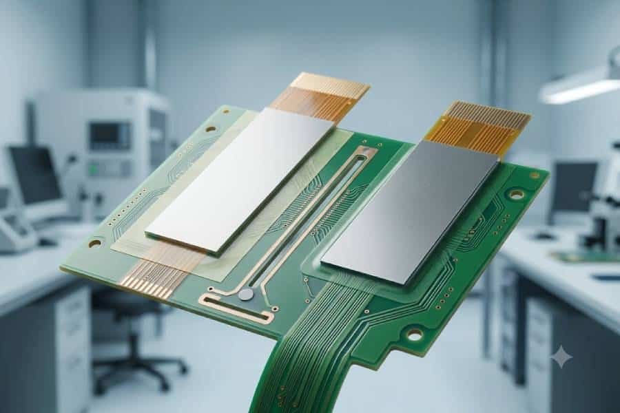
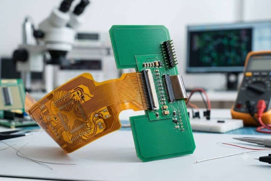
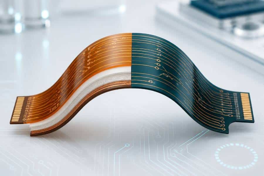
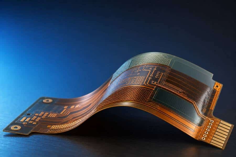
In flexible PCB design, a stiffener is a localized reinforcement layer added to specific areas of the board to provide mechanical support and improve assembly reliability. It is not part of the electrical circuit, but it helps harden delicate sections such as connector areas, SMT mounting zones, and other locations that need extra rigidity.
Flexible circuits are chosen for their thin profile, light weight, and bendability, but those same advantages also make them more vulnerable to mechanical stress. That is why stiffeners are widely used in FPC and flex PCB designs to improve durability, maintain thickness in critical areas, and reduce damage during handling and assembly.
In many applications, the right stiffener can also help meet connector mating requirements, support solder joints, and control where the board should or should not bend. For that reason, choosing the correct stiffener is an important part of flex PCB design, especially when the board must balance flexibility with structural stability.
What Is a Flex PCB Stiffener?
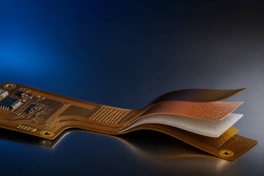
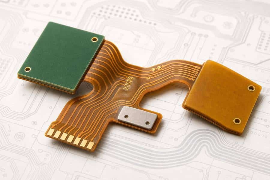
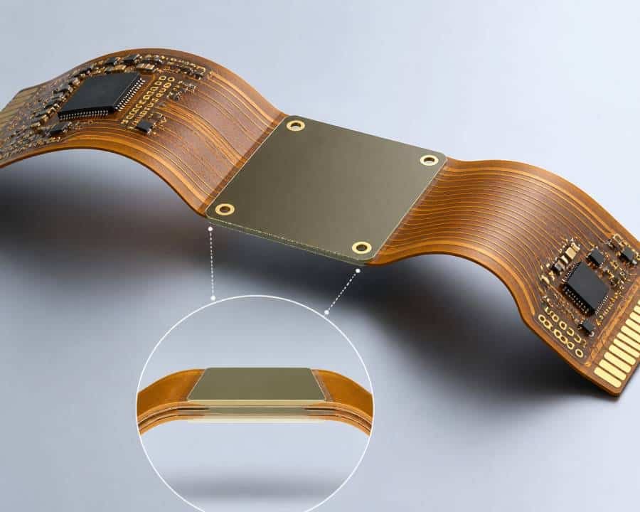
A flex PCB stiffener is a localized reinforcement layer added to specific areas of a flexible circuit to provide mechanical support, improve flatness, and make assembly easier. It is not an electrical part of the circuit; instead, it is a structural add-on used where the board needs extra rigidity, such as connector ends, component mounting areas, or other critical zones.
In practical terms, a stiffener helps a flexible board behave more like a rigid board only where needed. This is especially important in areas that must withstand soldering, connector insertion, or repeated handling during manufacturing and final assembly.
Most flex PCB stiffeners are made from materials such as FR4 or polyimide, although metal options may also be used for special requirements like higher strength or heat dissipation. The material choice depends on the application, required thickness, and whether the stiffened area must remain compatible with bending or assembly constraints.
A simple way to think about it is this: the flexible part of the circuit gives you bendability, while the stiffener gives you the support needed to protect the design where flexibility is no longer desirable.
Common Stiffener Materials
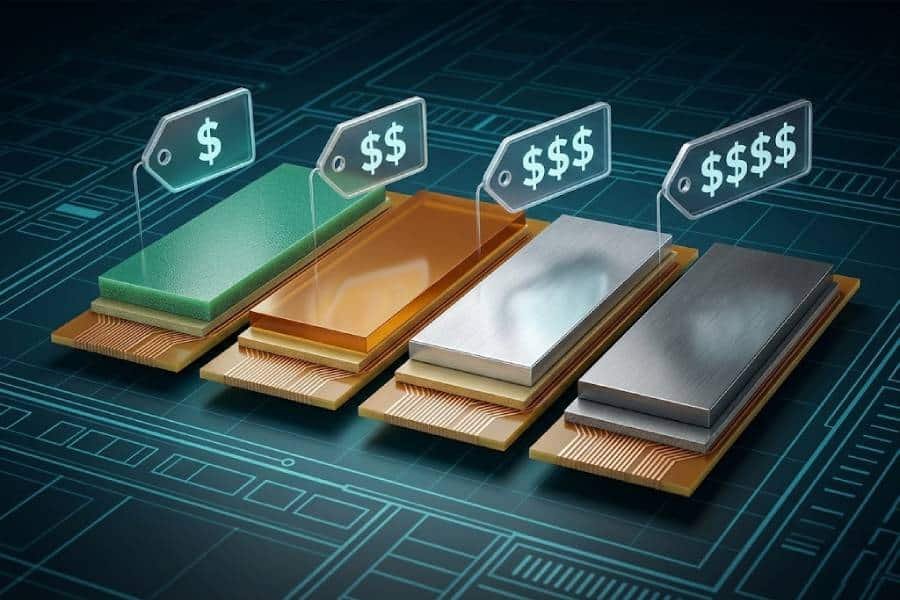
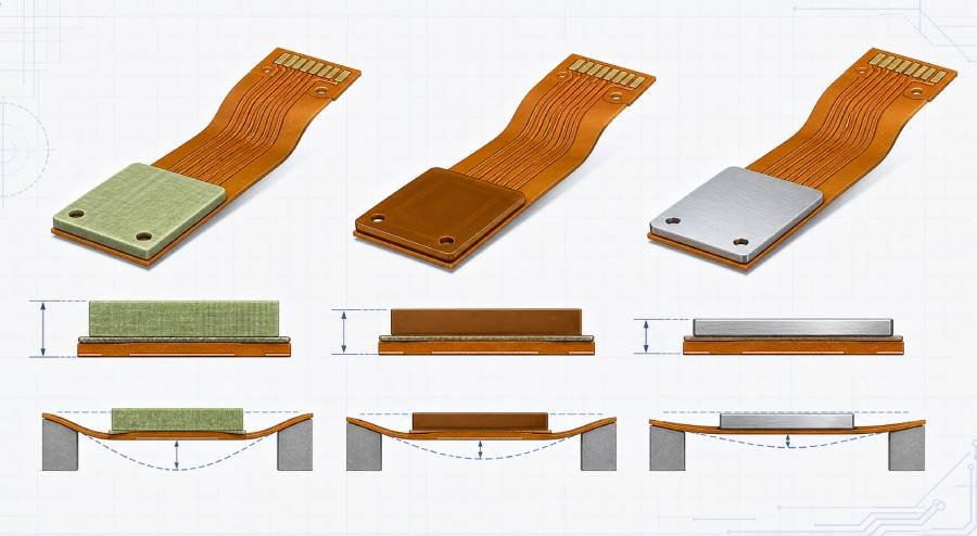
The most commonly used stiffener materials for flex PCB designs are FR4, polyimide, and metal options such as aluminum or stainless steel. Each material serves a different purpose, so the best choice depends on whether the application needs stronger support, better temperature resistance, or a closer match to the flex structure itself.
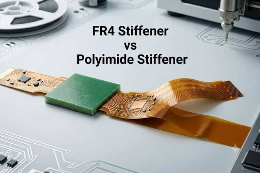
FR4 Stiffener
FR4 is one of the most common stiffener materials because it provides strong mechanical support at a relatively low cost. It is often used in connector areas, SMT mounting zones, and other places where the flex circuit needs to stay flat and rigid during assembly.
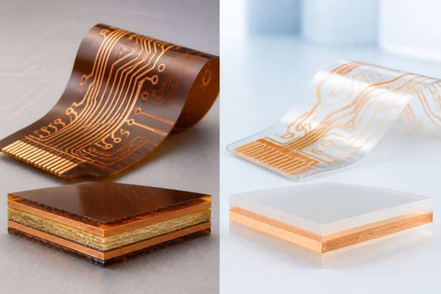
Polyimide Stiffener
Polyimide is a popular choice when the stiffened area still needs to remain relatively thin and compatible with the flex circuit structure. It is often used for ZIF connector areas, flex tails, and applications where thickness control matters and a less aggressive level of rigidity is acceptable.
Metal Stiffener
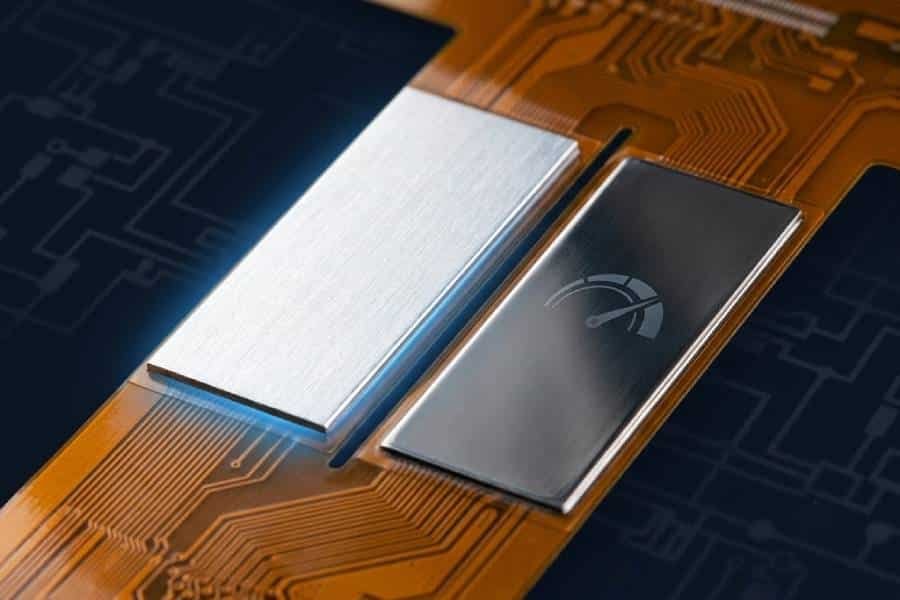
Metal stiffeners, such as aluminum or stainless steel, are used in more specialized cases where higher strength, wear resistance, or heat dissipation is required. They are less common than FR4 or polyimide, but they can be useful in demanding applications that need extra mechanical performance.
In general, FR4 is the first choice when the priority is support and cost efficiency, polyimide is preferred when thickness and flex compatibility matter more, and metal is used when the design has special structural or thermal requirements.
How to Choose by Application
The best stiffener choice depends on where the flex PCB is being used and what that area needs to do. In most cases, stiffeners are selected to support connectors, improve soldering stability, control bend zones, or meet special thermal and mechanical requirements.
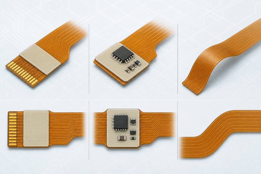
1. Connector Areas
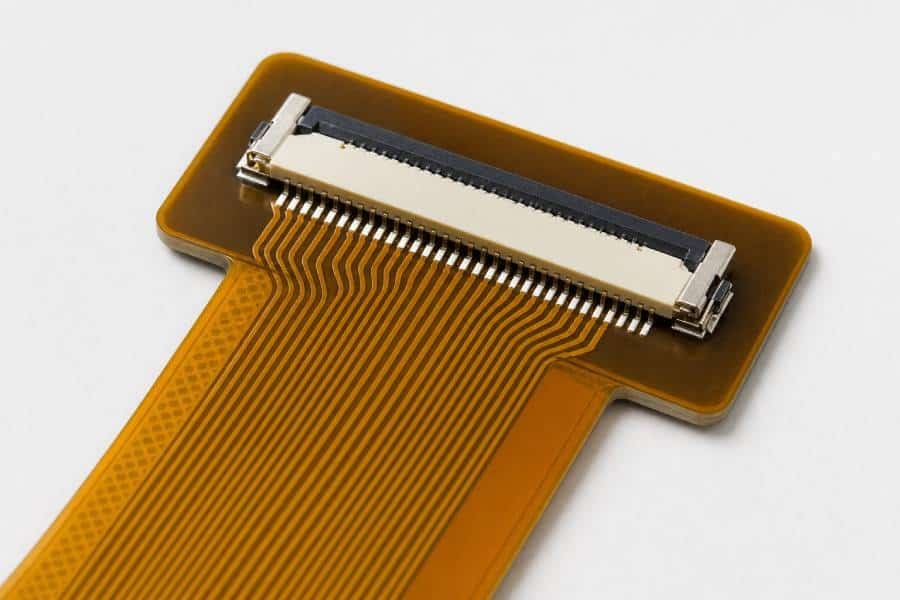
For connector ends, a stiffener is often used to create a stable, rigid insertion zone and reduce stress on the flex tail. This is especially important for repeated insertions, ZIF connectors, and interfaces that need controlled thickness and flatness.
2. SMT Component Areas
If surface-mount components are placed on the flex circuit, the stiffener helps provide a flat mounting surface and protects solder joints from deformation. In these areas, FR4 is often a strong choice because it offers solid mechanical support during assembly and handling.
3. Dynamic Bend Zones
If the area is expected to bend repeatedly, the stiffener should not be placed in the active bend region. Instead, it should be positioned to define or restrict the bend area, so the flex circuit can move safely without damaging traces or solder joints.
4. High-Temperature or Thermal Areas
For applications where heat dissipation matters, metal stiffeners such as aluminum may be considered. These are more specialized than FR4 or polyimide, but they can be useful when both support and thermal management are required.
5. Space-Constrained Designs
When the design has limited space and thickness control is critical, polyimide stiffeners are often a practical option. They are commonly used in ZIF connector areas and other locations where the board needs extra thickness without becoming too rigid or bulky.
A simple rule is this: use FR4 for stronger structural support, polyimide for thinner and more connector-sensitive areas, and metal only when the application has special mechanical or thermal needs.
Key Design Factors
Choosing the right stiffener is not only about material selection. The final design also depends on thickness, bend behavior, adhesive compatibility, assembly requirements, and the clearance between the stiffener and the actual flexing area.
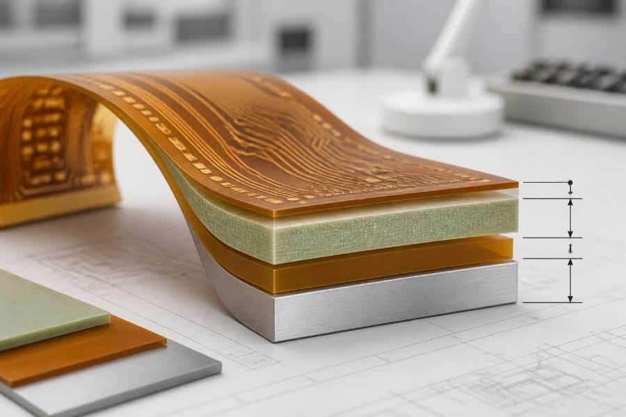
- Thickness Requirements
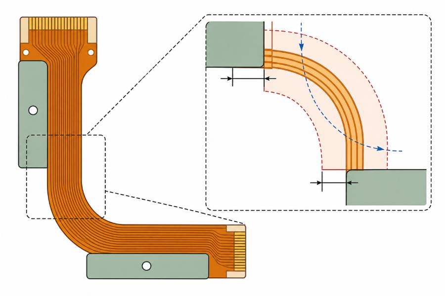
Stiffener thickness directly affects rigidity, connector fit, and assembly performance. In many designs, the goal is not to make the area as thick as possible, but to reach the target thickness required for ZIF insertion, component support, or handling stability. - Bend Radius and Stiffener Clearance
A stiffener should never interfere with the natural bend of the flex circuit. Designers normally keep a safety distance between the stiffener edge and the beginning of the bend zone, because placing the stiffener too close can increase stress concentration and reduce long-term reliability. - Assembly Process
The assembly method is another critical factor because connector insertion, SMT placement, soldering, and handling all place mechanical stress on the flex PCB. A well-chosen stiffener helps maintain flatness, improves process stability, and protects solder joints or pad areas during manufacturing. - Adhesive and Material Compatibility
The stiffener material must work well with the flex base material and the bonding method used in fabrication. Material mismatch, poor adhesive selection, or unsuitable thermal behavior can cause delamination, warpage, or performance issues during assembly and use. - Operating Environment
The actual application environment also matters, especially if the product will face vibration, repeated bending, or temperature changes. In these cases, the stiffener must be selected not only for support, but also for long-term reliability under real operating conditions.
A practical rule is to define the function of the stiffened area first, then choose the material, thickness, and placement that support that function without compromising the flexibility of the rest of the circuit.
Common Mistakes to Avoid
One of the most common mistakes in flex PCB stiffener design is treating the stiffened area like a normal rigid PCB section. In reality, the transition between flexible and stiffened regions is a mechanical stress point, so poor placement or wrong dimensions can quickly reduce reliability.
- Placing the Stiffener Too Close to the Bend Area
A stiffener should not be placed too close to an active bend zone. When the rigidized area is too near the bend, stress becomes concentrated at the transition edge, which can lead to cracking, delamination, or conductor failure over time. - Choosing the Wrong Thickness
A thicker stiffener does not always mean a better design. If the thickness does not match connector requirements, assembly needs, or the intended mechanical behavior of the flex tail, it can create insertion problems, excessive stiffness, or poor fit during assembly. - Ignoring SMT and Pad Support
When components or solder pads are placed on flexible areas without enough support, solder joints and pads can be damaged by bending, vibration, or handling. Stiffeners are often needed under these areas to improve coplanarity and protect the assembly during use. - Overlooking Material and Adhesive Compatibility
Another common issue is selecting a stiffener material without fully checking thermal behavior, bonding method, or application environment. A poor material or adhesive match can cause warpage, delamination, or long-term failure after soldering or field use. - Not Considering DFM Early
Many stiffener-related problems begin at the design stage, especially when bend zones, pad support, thickness targets, and spacing rules are not clearly defined for manufacturing. Early design review with the PCB manufacturer helps prevent avoidable mistakes before they become production issues.
A good rule is to design the stiffener around the real mechanical function of the area rather than adding it only after problems appear in assembly or testing.
Conclusion
Choosing the right flex PCB stiffener starts with understanding the function of the specific area rather than selecting a material by habit. In most designs, the stiffener is used to add local support, improve connector reliability, protect solder joints, and control thickness or bend behavior where the circuit should no longer remain fully flexible.
For most applications, FR4 and polyimide cover the majority of stiffener needs, while metal stiffeners are usually reserved for more specialized mechanical or thermal requirements. The best result comes from matching the stiffener material, thickness, and placement to the actual application, assembly process, and operating environment.
A well-designed stiffener does more than make a flex PCB feel stronger. It helps the entire design achieve better manufacturability, higher assembly stability, and longer-term reliability in real-world use.
FAQ
A stiffener is added to a flexible PCB to provide localized mechanical support in areas that should not bend freely. It is commonly used to protect connector zones, support component mounting areas, reduce stress on solder joints, and improve assembly reliability.
No. A stiffener is not an electrical layer and is not used for signal routing. Its main role is to reinforce specific sections of the flex PCB so that those areas can better withstand assembly, handling, and mechanical stress.
The most common stiffener materials are FR4, polyimide (PI), and metals such as stainless steel or aluminum. FR4 is usually selected for strong support, polyimide is often used where thickness control and flexibility compatibility matter, and metal is reserved for special structural or thermal needs.
Polyimide is often used for ZIF connector areas because it helps build the required insertion thickness while remaining more compatible with the flex circuit structure. The exact selection still depends on the connector specification and total finished thickness required by the design.
There is no single standard thickness for every design because the correct value depends on the application, connector requirements, and target rigidity. In practice, stiffener thickness is usually chosen to meet final assembly and mechanical requirements rather than simply making the board as stiff as possible.
No. A stiffener is only needed when a specific area requires added flatness, support, thickness control, or protection from stress. Small and simple flex circuits may not need one at all if there are no connectors, mounted components, or mechanically sensitive regions.
Yes. In some designs, different stiffener materials can be used on different parts of the same board to meet different functional needs. For example, one area may use polyimide to meet connector thickness requirements, while another uses FR4 to support SMT assembly.
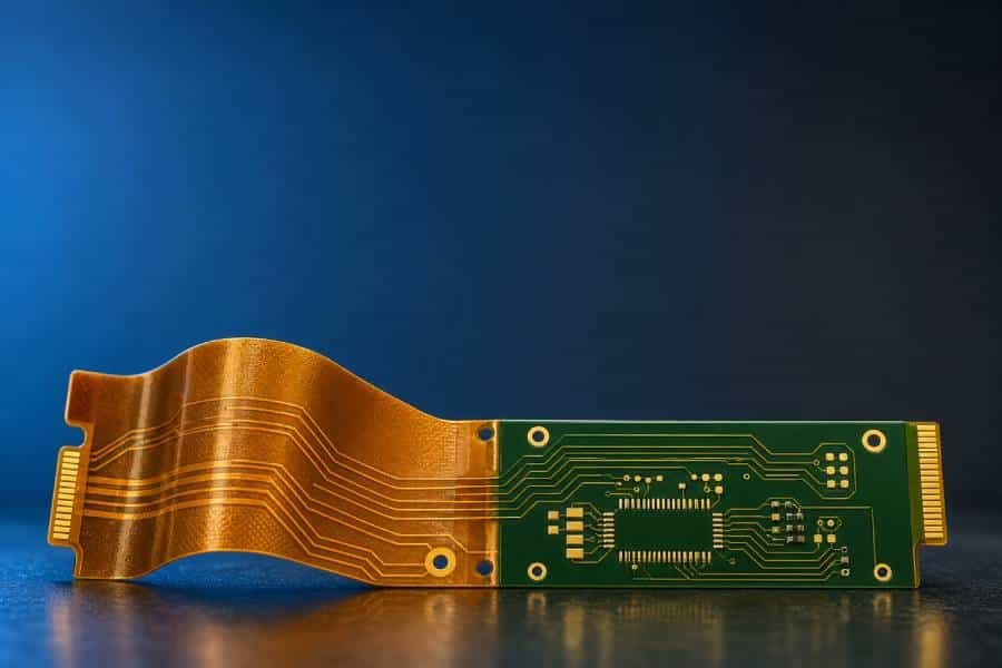
A flex PCB with a stiffener is still fundamentally a flexible circuit with added local mechanical support. A rigid-flex PCB is a different structure in which rigid and flexible sections are integrated into one stack-up and both sections can carry circuitry.
In most cases, no. A stiffener should not be placed directly in an active bend zone because it can create stress concentration and reduce reliability. It is usually better to place the stiffener outside the bend area and use it to help control where bending starts and stops.
It is best to confirm stiffener material, thickness, placement, and tolerance requirements early in the design stage. This helps avoid production issues related to connector fit, assembly performance, bend clearance, and long-term reliability.