Table of Contents
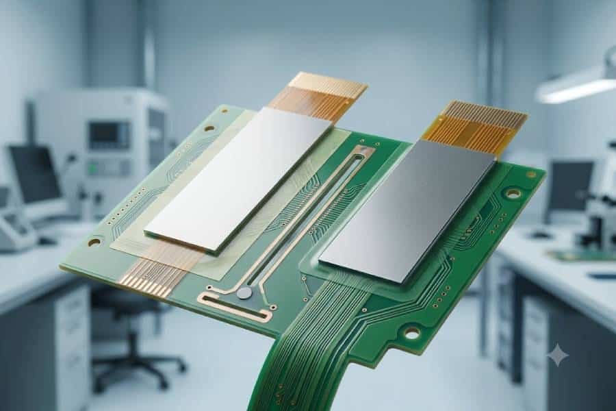
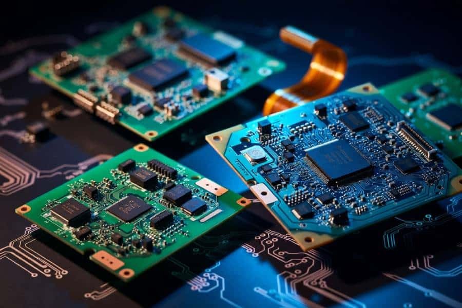
In flexible PCB design, stiffener thickness is one of the most important factors that affects mechanical support, connector fit, and assembly reliability. A stiffener is not an electrical layer; it is a localized reinforcement added to specific areas of the flex circuit to make those sections more rigid and stable.
The right thickness depends on the function of the area. For example, connector zones often need enough thickness to meet mating requirements, while SMT component areas need a flat and stable surface to protect solder joints. At the same time, areas close to bend zones must be designed carefully so the stiffener does not interfere with the flex performance of the board.
That is why choosing stiffener thickness is never just a material decision. It is a design choice that affects manufacturability, durability, and long-term reliability, especially when the flex PCB must balance flexibility in one area and rigidity in another.
What Does Stiffener Thickness Mean?
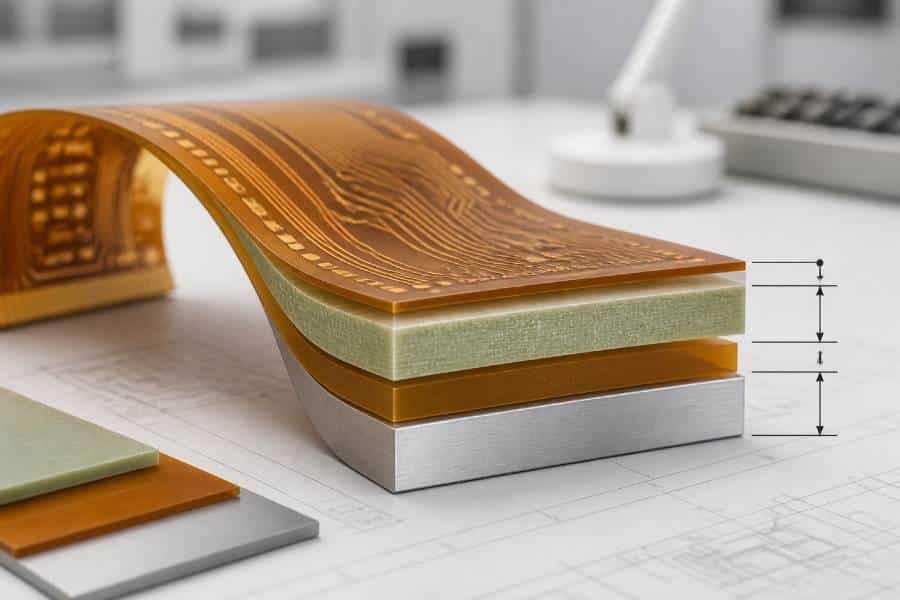
Stiffener thickness refers to the physical thickness of the reinforcement layer added to a flexible PCB in specific areas. It is one of the main factors that determines how much support the stiffener provides, especially in connector zones, SMT mounting areas, and other sections that need to stay flat and stable.
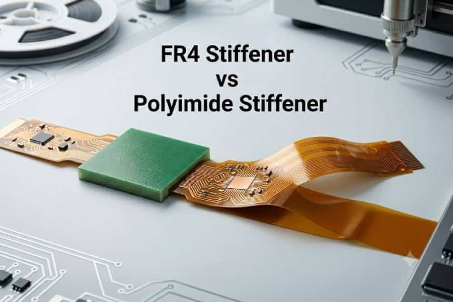
In practice, thicker stiffeners usually provide more rigidity, while thinner stiffeners are better when the design needs support without adding too much bulk. For example, FR4 stiffeners are commonly used in thicker ranges for stronger support, while polyimide stiffeners are often chosen when the goal is to meet thickness requirements with a smaller added profile.
Thickness also affects how the flex PCB behaves during assembly and use. If the stiffener is too thin, it may not give enough support for the connector or components; if it is too thick, it can make the area too rigid, interfere with insertion, or create transition stress near the bend region.
A useful way to think about stiffener thickness is that it must satisfy both mechanical and assembly requirements at the same time. In other words, the “right” thickness is the one that gives the needed strength and flatness without compromising fit, flexibility, or manufacturability.
Common Thickness Ranges by Material
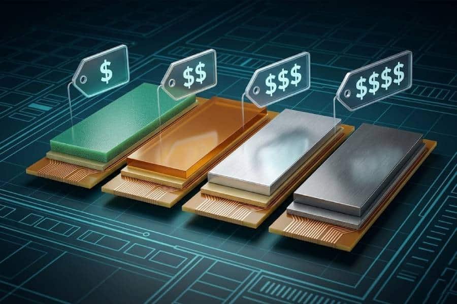
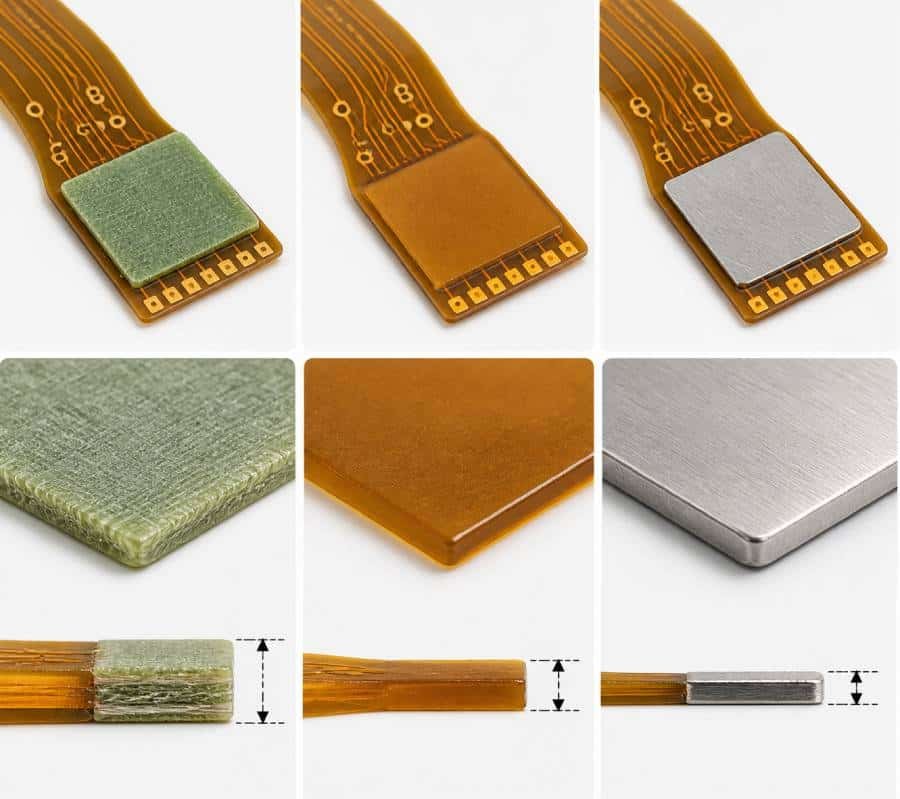
Different stiffener materials usually fall into different thickness ranges, and those ranges reflect how the material behaves in real flex PCB designs. In general, polyimide is used in thinner sections, FR4 covers the most common support ranges, and metal stiffeners are selected when the design needs higher rigidity or special mechanical performance.
- Polyimide Stiffener
Polyimide stiffeners are typically used in thinner ranges, often around 0.05 mm to 0.25 mm, with 0.05 mm, 0.075 mm, 0.1 mm, 0.125 mm, 0.15 mm, and 0.2 mm being common choices. They are often preferred when the design needs added thickness for connector areas but still wants to keep the structure relatively slim. - FR4 Stiffener
FR4 is the most common stiffener material for flex PCB support, and its thickness usually ranges from about 0.2 mm to 1.5 mm or 1.6 mm. Common values include 0.2 mm, 0.3 mm, 0.4 mm, 0.5 mm, 0.6 mm, 0.8 mm, 1.0 mm, 1.2 mm, and 1.5 mm, depending on how much rigidity the design needs. - Metal Stiffener
Metal stiffeners, such as aluminum or stainless steel, are used in more specialized applications, and their thickness commonly starts around 0.1 mm and can extend to higher values depending on the material and mechanical requirement. These options are less common than FR4 or polyimide, but they are useful when extra strength or thermal performance is needed.
These thickness ranges are not fixed rules. They are practical starting points, and the final thickness should always be chosen according to connector specifications, support requirements, and how much rigidity the area actually needs.
How to Choose Thickness by Application
The right stiffener thickness should be selected according to the function of the specific area, not by material alone. In practice, connector interfaces, SMT assembly zones, bend-adjacent regions, and thermally demanding sections all require different thickness priorities.
- Connector Areas
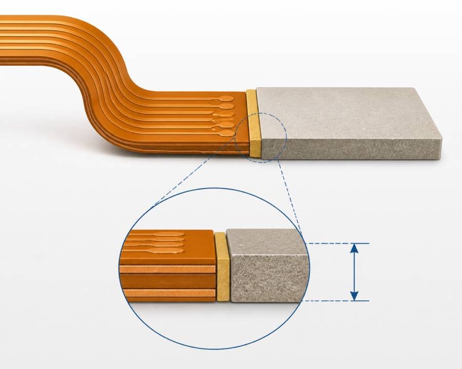
For connector ends, the main target is usually the final finished thickness at the mating interface rather than the stiffener thickness by itself. That final value includes the flex circuit, adhesive, and stiffener together, so if the stack-up is too thin the connector may not hold properly, and if it is too thick the tail may not insert or lock correctly. - ZIF Connector Zones
ZIF connector areas often use polyimide stiffeners because they help build the required insertion thickness while keeping the tail relatively thin and controlled. Many designs target common ZIF thickness requirements such as 0.2 mm or 0.3 mm total finger thickness, but the actual value must always follow the connector datasheet. - SMT Component Areas
For SMT mounting zones, the goal is to provide enough rigidity and flatness to support component placement and soldering. In these cases, FR4 is often preferred, and the thickness is chosen based on the mechanical load, board size, and how much support the assembly process needs. - Bend-Adjacent Support Areas
If the stiffener is placed near a bend region, the design should focus on support without creating a harsh mechanical transition. A thicker stiffener may give more rigidity, but it can also increase stress near the bend, so thickness and placement must be balanced carefully. - Thermal or High-Strength Applications
When the design needs more structural strength or some thermal benefit, metal stiffeners may be considered. In these applications, thickness is selected not only for rigidity but also for environmental durability, space constraints, and the mechanical demands of the finished product.
A practical way to choose thickness is to start with the end-use requirement first, then work backward to determine the total stack-up needed in that area. This approach is much more reliable than selecting a standard thickness first and hoping it fits the application later.
Key Factors That Affect Thickness Selection
Selecting the right stiffener thickness is not just about choosing a standard material value. The final decision usually depends on connector requirements, total stack-up thickness, bend behavior, assembly conditions, and the mechanical load the area must handle.
- Connector Requirements
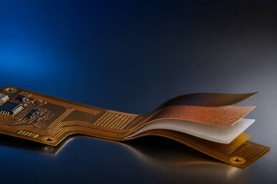
For many flex PCB designs, the most important factor is the connector specification. In connector and ZIF applications, the real target is usually the final thickness at the insertion area, which includes the flex circuit, adhesive, and stiffener together rather than the stiffener alone. - Total Stack-Up Thickness
Stiffener thickness must be evaluated as part of the full local stack-up. Base material thickness, copper thickness, adhesive layers, and coverlay all contribute to the final dimension, so even a small change in one layer can affect connector fit or assembly performance. - Mechanical Load
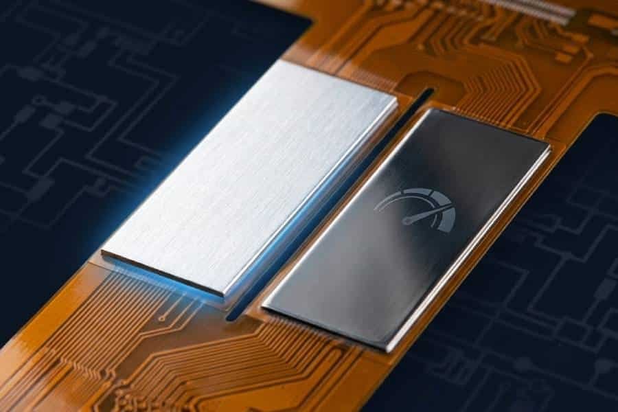
The expected mechanical load on the area also matters. If the section will support components, tolerate repeated insertion, or be handled frequently during assembly, it may need a thicker or stiffer reinforcement to maintain flatness and structural stability. - Bend Radius and Clearance
Thickness selection must also consider how close the stiffened area is to a bend region. Thicker sections increase rigidity, but they can also raise stress near bend transitions, so designers normally leave a safe clearance between the stiffener edge and the active bend area. - Assembly Process
SMT placement, soldering, and manual handling can all influence the thickness choice. A stiffener that is too thin may not provide enough flatness for reliable assembly, while one that is too thick may create unwanted transition stress or make the flex harder to process. - Material and Bonding Compatibility
Different materials provide different support levels at the same thickness, so the thickness cannot be selected independently from the material itself. Bonding method and material compatibility also matter because poor matching can affect reliability, delamination resistance, and long-term performance. - Cost and Manufacturability
Common thickness values are often easier to source and fabricate, while unusual thickness combinations may increase cost or complicate production. For that reason, it is usually better to align the design with standard material options whenever the application allows.
A good rule is to start with the functional requirement of the reinforced area, then verify the total thickness, bend behavior, and manufacturing feasibility before locking in the final value.
Common Mistakes to Avoid
One of the biggest mistakes in stiffener thickness selection is focusing only on the material thickness while ignoring the final local stack-up. In many flex PCB designs, what actually matters is the total finished thickness at the connector, component, or support area, not the stiffener layer by itself.
- Choosing Thickness Without Checking the Final Connector Fit
A common error is selecting a stiffener first and only later checking whether the finished tail thickness matches the connector requirement. This often causes insertion problems, poor locking force, or unreliable contact in ZIF and other connector applications. - Using a Thickness That Is Stronger Than Necessary
More thickness does not always mean a better design. If the stiffener is too thick, it can make the reinforced area overly rigid, increase transition stress, and create assembly difficulties that would not exist with a more balanced thickness choice. - Placing a Thick Stiffener Too Close to a Bend Zone
A thick stiffener near an active bend area can concentrate stress at the transition edge and reduce long-term reliability. Designers should leave enough clearance between the stiffener edge and the bend zone so the flex section can move without excessive strain. - Ignoring Overlap and Edge Design
Stiffener thickness is not the only mechanical factor that matters. Inadequate overlap, sharp corners, and poor edge transition design can all create stress points, even when the thickness itself seems reasonable. - Forgetting Assembly and Process Constraints
Some thickness choices look acceptable in theory but create problems during fabrication or assembly. For example, unusual thickness combinations, poor alignment with soldering access, or excessive variation across the design can increase cost, lead time, and manufacturing risk. - Not Standardizing When Possible
Using too many special thickness values in one design can complicate sourcing and production. In many cases, choosing common laminate thicknesses helps reduce fabrication complexity while still meeting the functional requirement.
A practical rule is to choose the minimum thickness that fully satisfies the application, then verify connector fit, bend behavior, and manufacturability before final release.
Conclusion
Choosing the right flexible PCB stiffener thickness is not about picking the thickest option available. The correct thickness is the one that meets the mechanical, assembly, and connector requirements of a specific area while still preserving the intended flex behavior of the rest of the circuit.
In most designs, thickness selection should start with the application itself, whether the goal is connector fit, SMT support, bend control, or added structural stability. From there, the material, local stack-up, and manufacturing constraints can be matched to achieve the required performance without adding unnecessary rigidity or cost.
A well-chosen stiffener thickness improves more than just local support. It also helps the flex PCB assemble more smoothly, perform more reliably, and maintain its durability over time in real operating conditions.
FAQ
Flexible PCB stiffener thickness refers to the thickness of the reinforcement layer added to a local area of a flex circuit to improve rigidity, flatness, and mechanical support. It affects connector fit, SMT stability, and how the reinforced area behaves during assembly and use.
No. Stiffener thickness is only one part of the final local thickness. The actual finished thickness in a connector or reinforced area also includes the flex circuit, adhesive, copper, and coverlay or other local stack-up layers.
Connector areas often require a specific finished thickness so the flex tail can insert and lock correctly. If the local thickness is too thin or too thick, it may cause poor mating, unreliable contact, or assembly issues.
FR4 stiffeners are commonly available in a wide range, and many standard values used in flex PCB design fall between about 0.2 mm and 1.5 mm or 1.6 mm. Common FR4 thicknesses are often selected for connector support, SMT flatness, and mechanical rigidity.
Polyimide stiffeners are usually chosen in thinner ranges than FR4, especially when the goal is to meet connector thickness requirements without adding excessive rigidity. They are commonly used in ZIF connector regions and other thin flex tail applications, often in the 0.05 mm to 0.25 mm range.
Start with the connector manufacturer’s required insertion thickness, then calculate the total local stack-up needed to reach that value. The stiffener thickness should be selected only after considering the base flex thickness, adhesive, and coverlay contribution.
No. A thicker stiffener provides more rigidity, but it can also create insertion problems, increase stress near bend transitions, and reduce flexibility more than necessary. The best thickness is the minimum value that fully meets the mechanical and assembly need.
Yes. As local thickness increases, that area becomes more rigid and less suitable for bending. If a thick stiffener is placed too close to an active bend region, it can increase stress concentration and reduce long-term reliability.
Yes. Stiffener thickness should be considered early because it affects connector fit, material selection, mechanical behavior, and manufacturability. Late changes can create problems in both design documentation and production.
No. A stiffener is only needed when a local area requires extra support, controlled thickness, or protection from mechanical stress. Small or simple flex circuits without connectors or mounted components may not need one at all.