Table of Contents
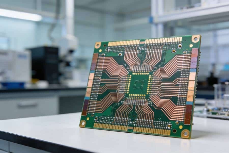
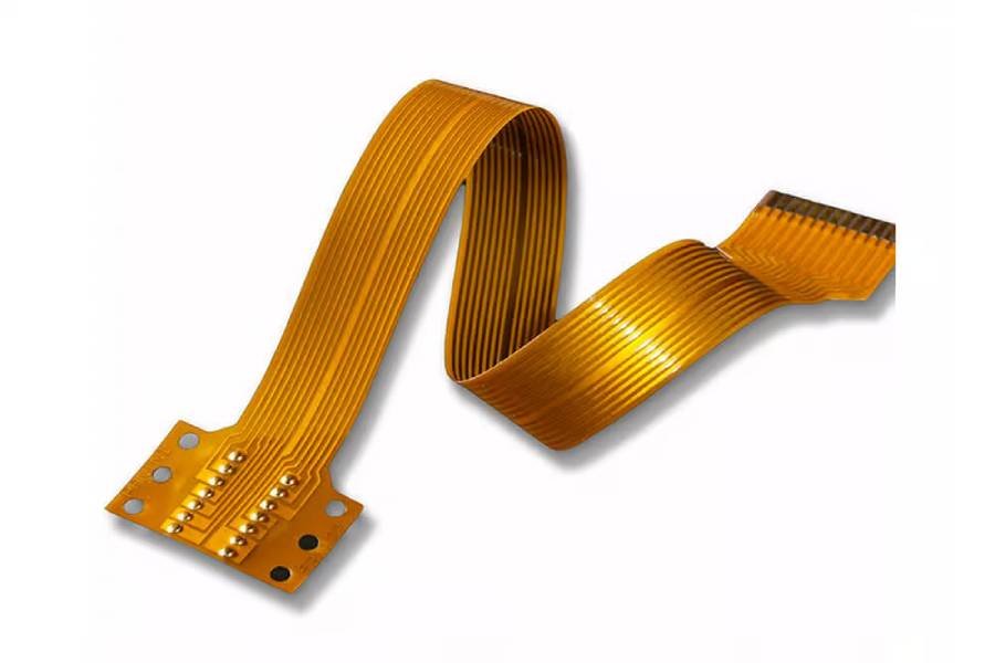
Flexible PCBs are widely used in compact electronic devices because they can bend, twist, and fit into tight spaces where rigid boards are not practical. Their performance depends not only on the circuit design, but also on the materials used in the stackup, especially the copper conductor and flexible base film such as PI or PET.
Among the available conductor options, electrolytic copper foil is a cost-effective choice for many flexible PCB applications. In this guide, we will explain what electrolytic copper foil is, how it is used in flex PCB manufacturing, where it works best, and what factors to consider when selecting the right material for your design.
Flexible PCB Materials Overview
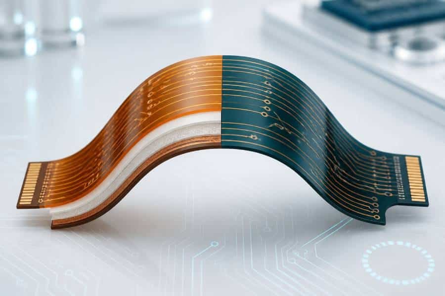
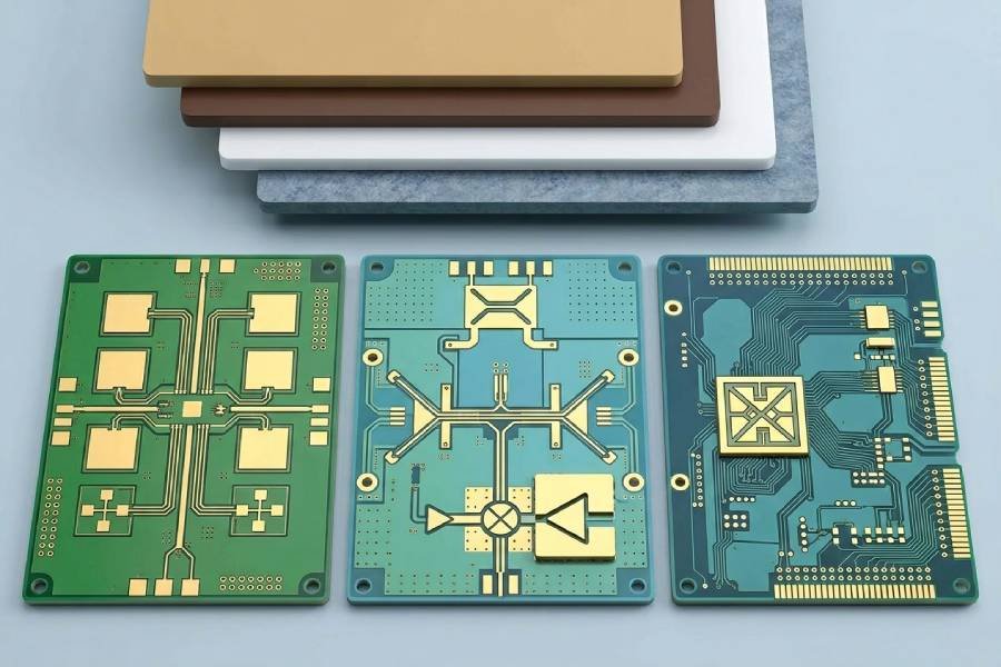
A flexible PCB is built from a combination of flexible substrate films, copper conductors, adhesives, and protective layers. In most designs, the substrate is polyimide (PI) or polyester (PET), while the conductive layer is copper foil and the outer protection is usually coverlay or a flexible solder mask.
Material selection has a direct impact on flexibility, thermal performance, thickness, and reliability. That is why engineers must consider not only the copper foil, but also the base film, adhesive system, coverlay, and any local reinforcement such as stiffeners before finalizing a flex circuit design.
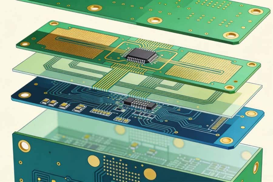
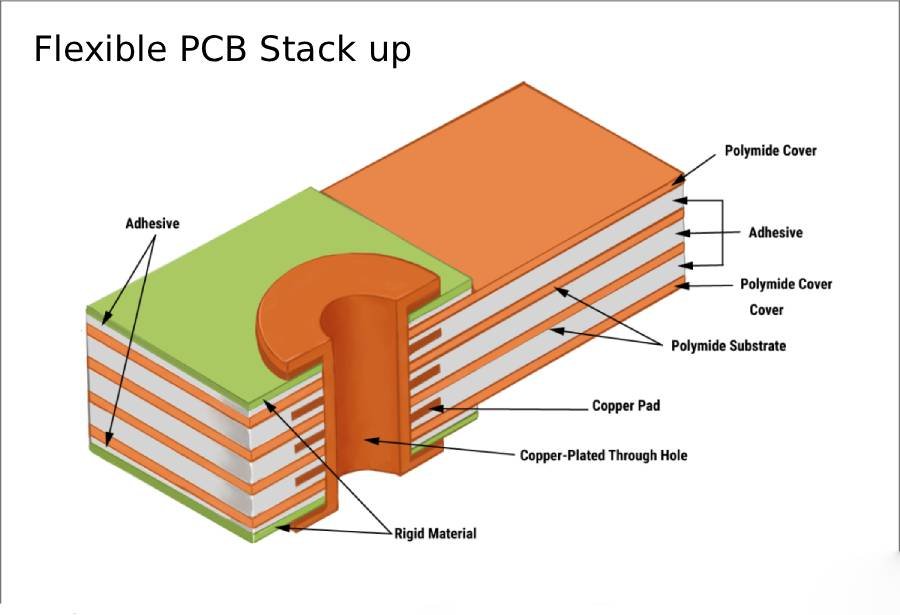
Common Layer Structure
Most flexible PCBs follow a similar layer structure: a base film provides insulation and mechanical flexibility, a copper layer forms the circuit traces, and a protective layer seals the exposed conductors. Depending on the application, an adhesive layer may be included between the film and copper, and stiffeners may be added in connector or component areas to improve local support.
Base Materials: PI and PET
Polyimide is the most common base material for flexible PCBs because it offers strong heat resistance, dimensional stability, and good mechanical durability.
PET is a lower-cost alternative that can work well in less demanding applications, but it generally has lower thermal resistance and weaker performance in dynamic bending environments.
Coverlay, Adhesives, and Stiffeners
Coverlay is commonly used to protect and insulate the outer circuit layers in flex PCB designs, and it is often made from polyimide combined with adhesive.
Adhesive-based constructions are usually simpler and more economical, while adhesiveless constructions can offer thinner profiles and better performance for higher-end designs.
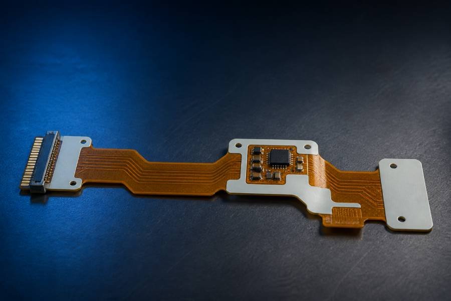
Stiffeners are added only where mechanical reinforcement is needed, such as connector tails, component zones, or assembly areas.
Why This Matters
Understanding the full material stack helps explain why copper foil cannot be evaluated in isolation. The best copper choice depends on the substrate, protection layer, bend requirements, and cost target, so the material system should always be selected as a whole.
What Is Electrolytic Copper Foil?
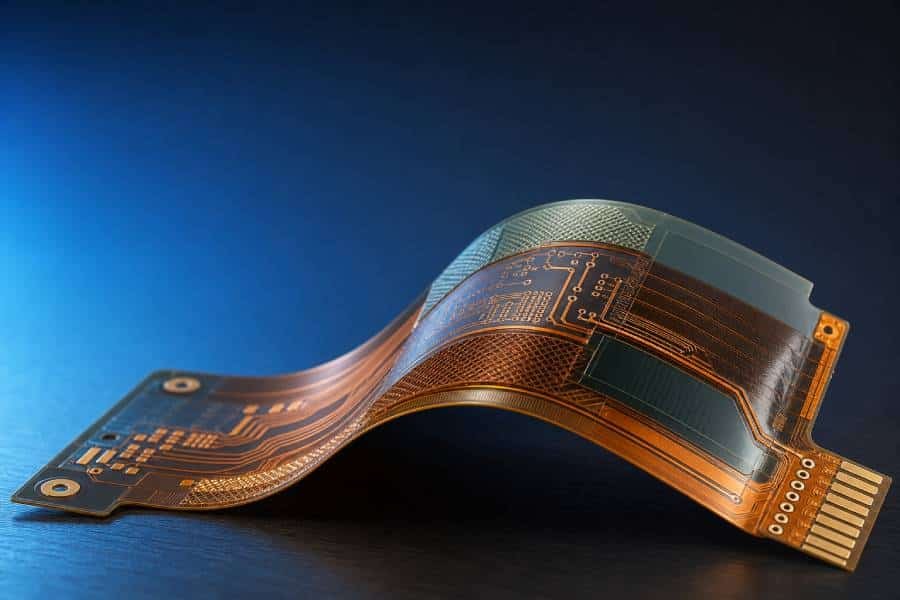
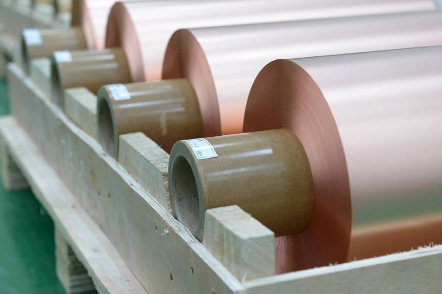
Electrolytic copper foil, also called ED copper foil, is a copper conductor made by depositing copper ions onto a rotating drum through an electrochemical process. This method produces a foil with a characteristic grain structure and a slightly rough surface, which helps improve adhesion to flexible substrates during PCB fabrication.
In flexible PCB applications, electrolytic copper foil is valued for its cost efficiency, stable manufacturing process, and good electrical performance. It is not the most flexible copper option, but it is widely used in flex circuits where design requirements are moderate and bending stress is limited.
How It Is Manufactured
The basic process starts with an electrolytic solution containing copper, where electric current causes copper ions to deposit onto a cathode drum. As the drum rotates, the foil builds up continuously and is then peeled off, treated for oxidation resistance, and roughened or surface-finished for better bonding performance.
Key Properties
Electrolytic copper foil is known for its good conductivity, predictable thickness control, and relatively low production cost. Its microstructure is typically columnar, which makes it less ductile than rolled annealed copper, especially in applications that require repeated bending.
Electrolytic Copper Foil vs. Rolled Annealed Copper
The main difference between the two lies in their formation and mechanical behavior. Rolled annealed copper is mechanically rolled and heat-treated, which gives it better extensibility and makes it more suitable for dynamic flexing, while electrolytic copper foil is generally preferred when cost and process efficiency matter more than maximum bend life.
Benefits of Electrolytic Copper Foil in Flexible PCBs
Electrolytic copper foil is widely used in flexible PCB production because it offers a practical balance of performance, cost, and manufacturability. For many flex circuit designs, especially static or low-bend applications, it provides enough electrical capability without the higher material and processing cost of more flexible copper types.
Cost Efficiency and Supply Availability
One of the biggest advantages of electrolytic copper foil is its lower production cost. Because it is manufactured through an electrochemical deposition process and can be produced efficiently at scale, it is often easier to source and more economical than rolled annealed copper.
Good Electrical Performance
Electrolytic copper foil provides reliable conductivity for many flexible PCB applications. In designs where electrical performance is important but extreme repeated bending is not required, ED copper can deliver stable circuit performance while keeping the overall build economical.
Manufacturing Compatibility
Another benefit is its strong compatibility with standard PCB fabrication processes. The foil’s surface characteristics support adhesion during lamination and help manufacturers maintain consistent production quality, which makes it a practical option for high-volume manufacturing.
Suitable for Static Flex Applications
Electrolytic copper foil works especially well in static flex designs, where the board may be bent during installation but does not need to flex repeatedly during operation. In these cases, the material’s lower flexibility is usually acceptable because the design prioritizes cost efficiency and production stability.
Balanced Design Choice
For many consumer, industrial, and cost-sensitive products, electrolytic copper foil offers the right balance between performance and budget. When the application does not demand the highest bend life, it can be a sensible and widely accepted conductor choice for flexible PCBs.
Limitations and Design Considerations
Although electrolytic copper foil offers clear cost and manufacturing advantages, it is not the best option for every flexible PCB design. Its main limitation is lower ductility compared with rolled annealed copper, which means it is more likely to develop cracks when exposed to repeated bending, vibration, or long-term mechanical stress.
Lower Flex Durability
The grain structure of ED copper makes it less tolerant of repeated flexing. In static flex applications, this may not be a major issue, but in dynamic designs where the circuit bends regularly during use, fatigue resistance becomes a critical concern.
Bend Radius Matters
Mechanical reliability is strongly affected by bend radius. Industry guidance commonly recommends a more conservative bend radius for dynamic flex circuits than for static ones, and thinner constructions generally perform better in tight-bend conditions, while thicker copper increases mechanical stress in the bend area.
Thickness Is a Trade-Off
Thicker copper can improve current-carrying capacity, but it also reduces flexibility and may shorten bend life. This creates a trade-off between electrical performance and mechanical durability, especially in designs where space is tight and the board must move during operation.
The Material System Must Work Together
Copper foil should never be selected in isolation. Adhesive systems, substrate type, coverlay choice, and stiffener placement all influence the final bending performance, and poor combinations can increase the risk of delamination, cracking, or local stress concentration.
When ED Copper Is Not the Best Choice
Electrolytic copper foil is generally not ideal for high-cycle dynamic flex applications, vibration-heavy environments, or designs with very small bend radii. In those cases, rolled annealed copper and more optimized flex constructions are usually preferred because they offer better fatigue life and mechanical reliability.
How Flexible PCBs Are Built
Flexible PCB fabrication starts with the base film and copper-clad material, then moves through imaging, etching, drilling, plating, coverlay lamination, and final profiling. Compared with rigid boards, the process has extra attention on dimensional stability and bend reliability, because the materials must survive both manufacturing heat and later mechanical movement.
Material Preparation
The first step is preparing the flexible laminate, which usually combines a PI or PET base film with copper foil and, depending on the construction, an adhesive layer. The material is cut to size and cleaned so the copper surface is ready for the next process steps.
Circuit Patterning and Etching
After preparation, the circuit pattern is transferred onto the copper through photo imaging or similar pattern-generation methods. Unwanted copper is then removed by etching, leaving the designed traces on the flexible substrate.
Drilling and Plating
Holes, pads, and via features are formed using mechanical or laser drilling, depending on the design requirements. Copper plating is then applied where needed to create electrical connections between layers and to support interlayer interconnection.
Coverlay and Protection
Once the circuit is formed, coverlay is laminated onto the flex area to protect the traces while preserving flexibility. Coverlay is commonly a PI or PET film with adhesive, and it is cut or windowed to expose pads and component areas before lamination.
Stiffeners, Profiling, and Testing
Stiffeners are added in connector areas or other zones that need extra mechanical support. The board is then routed or punched to final shape, followed by electrical testing and final inspection to confirm quality and reliability.
Why This Step Matters
This manufacturing sequence explains why copper choice matters so much in flex designs. The copper must not only conduct electricity well, but also survive lamination, drilling, coverlay bonding, and the mechanical stresses that come with flexing in service.
How to Select the Right Copper Foil
Choosing the right copper foil for a flexible PCB depends first on how the circuit will move in real use. The most important question is whether the design is static flex, where the board bends only during installation, or dynamic flex, where it bends repeatedly during operation.
Start With the Application Type
For static flex designs, electrolytic copper foil is often a practical and economical choice. For dynamic flex applications, rolled annealed copper is usually preferred because it offers better ductility and longer fatigue life under repeated bending.
Consider Bend Radius and Flex Cycles
Bend radius and expected flex cycles should be defined early in the design stage. General flex design guidance shows that tighter bend radii and higher cycle counts demand more flexible materials, and this usually pushes the design toward thinner copper and RA foil rather than standard ED foil.
Match Copper Thickness to Electrical Needs
Copper selection is not only a mechanical decision; it must also support the required current and thermal performance. Thicker copper improves current-carrying capacity and lowers resistance, but it also increases stiffness, so many flex designs use the thinnest copper that still meets electrical requirements.
Review the Full Stackup
Copper foil must be selected together with the substrate, adhesive system, coverlay, and layer count. A thin, well-balanced stackup can improve bend reliability, while a heavier and more complex stackup may require design compromises even if the copper type itself is appropriate.
Involve the PCB Manufacturer Early
Material selection should be confirmed with the fabricator before final release. Many design guides recommend defining the application type, copper type, thickness, bend radius, and stackup requirements in advance so the manufacturer can verify feasibility and reliability.
A Practical Rule of Thumb
If the circuit only needs to flex during assembly or installation, ED copper is often sufficient and more cost-effective. If the circuit must bend repeatedly in service, RA copper is usually the safer choice despite the higher material cost.
Material Choices Beyond Copper
Copper foil is only one part of a reliable flex PCB stackup. The final performance of a flexible circuit also depends on the substrate film, coverlay, adhesive system, and any reinforcement materials used in high-stress or assembly-critical areas.
Choosing Between PI and PET
Polyimide is the most common substrate for flexible PCBs because it offers strong thermal stability, mechanical durability, and good performance in demanding environments. PET is a lower-cost option that can work in simpler static applications, but it usually has lower heat resistance and is less suitable for harsh assembly or dynamic bending conditions.
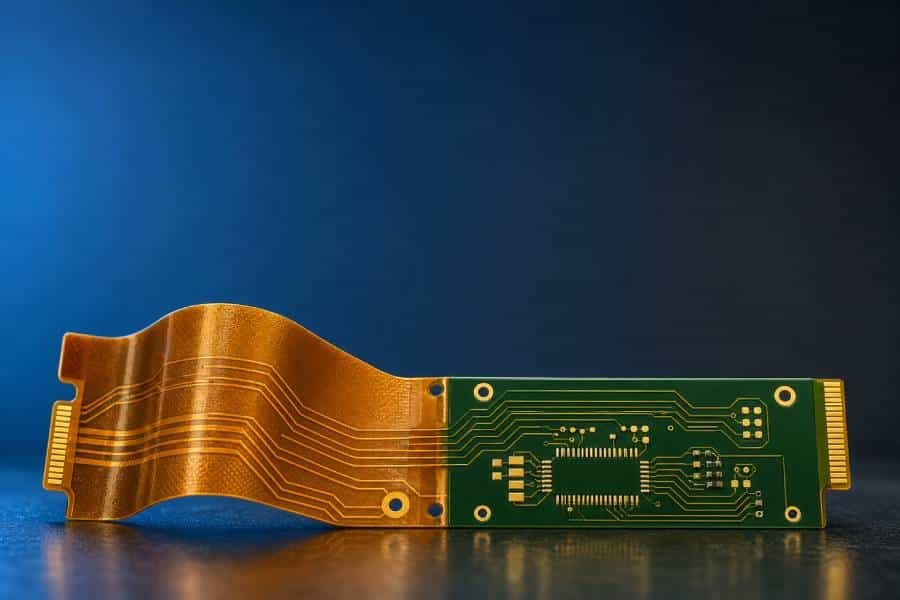
Coverlay vs. Flexible Solder Mask
In flex regions, coverlay is often preferred because it provides better mechanical protection and long-term bending reliability. Flexible solder mask can still be useful in component-dense areas or rigidized sections, and many designs use both materials in different zones of the same board.
Adhesive-Based vs. Adhesiveless Structures
Flex core materials are available in adhesive-based and adhesiveless constructions. Adhesive-based cores are usually more economical and offer strong peel strength, while adhesiveless structures are thinner and often perform better when flexibility, thermal resistance, and dimensional stability are critical.
When to Use Stiffeners
Stiffeners are added when certain areas of the flex PCB need extra support for connectors, component placement, or handling during assembly. Common stiffener materials include FR4, polyimide, and sometimes metal, depending on the mechanical and thermal requirements of the design.
Think in Terms of the Full Stackup
The best material choice is rarely about finding the single “best” substrate or protective layer. Instead, the goal is to build a balanced stackup that matches the application’s bend behavior, assembly process, environment, and cost target.
Typical Applications
Flexible PCBs are used across many industries because they save space, reduce wiring complexity, and fit into compact or moving assemblies. The choice of copper foil depends on how much bending the product will experience in actual use, so application type is closely tied to material selection.
Consumer Electronics
Flex PCBs are widely used in smartphones, wearables, cameras, tablets, and other compact consumer devices. In lower-motion products or static interconnect sections, electrolytic copper can be a cost-effective option, while highly dynamic products such as foldable devices usually need more flexible conductor choices.
Automotive Electronics
Automotive systems use flexible PCBs in displays, sensors, lighting modules, battery systems, and infotainment assemblies where compact routing and vibration resistance are important. Because automotive environments often involve thermal cycling and mechanical stress, copper and substrate choices must be matched carefully to the reliability target.
Medical and Industrial Devices
In medical devices, flex PCBs are common in wearables, monitoring systems, diagnostic equipment, and compact implant-adjacent electronics because they support lightweight and space-saving designs. Industrial electronics also rely on flex circuits in sensors, moving assemblies, and control modules where routing flexibility and mechanical durability are important.
Cost-Sensitive Static Flex Applications
Electrolytic copper foil is especially suitable for static flex cables, connector tails, and other applications where the board is bent mainly during installation rather than repeated operation. In these designs, the lower cost of ED copper can provide a practical advantage without sacrificing required performance.
Match Material to Motion
The most important rule is to match the copper type to the motion profile of the product. Static and low-motion applications can often use ED copper successfully, while continuous-motion and high-cycle designs usually require materials with better fatigue resistance.
Design and Procurement Tips
Good flex PCB results depend on more than choosing the right copper foil. Design teams and buyers should align early on bend requirements, stackup, manufacturability, and material availability so the final board can meet both performance and delivery goals.
Define the Motion Profile Early
The first step is to clearly define whether the board is static flex or dynamic flex. That decision affects copper type, thickness, bend radius, routing rules, and long-term reliability, so it should be fixed before the layout is finalized.
Design for Manufacturability
Flex circuits are more sensitive to bend area layout, stackup balance, and material combinations than standard rigid boards. Many DFM guidelines recommend clearly marking bend regions, avoiding vias and components in those zones, and selecting dimensions that stay within the fabricator’s normal process window.
Standardize Where Possible
For cost and procurement efficiency, it helps to reduce unnecessary material variation. Using standard copper weights, common substrate options, and realistic manufacturing tolerances can simplify sourcing, improve yield, and shorten lead time.
Work With the Manufacturer Early
Flex PCB fabrication works best when the supplier is involved before the design is released. Early collaboration helps verify stackup feasibility, confirm bend radius rules, review material availability, and avoid redesigns caused by unsupported structures or unrealistic tolerances.
Prepare Clear Production Data
Procurement and manufacturing teams need complete documentation, not just Gerber files. A strong release package should define materials, copper thickness, stiffener locations, bend areas, special handling notes, and any reliability requirements that affect fabrication or inspection.
Validate Before Volume Production
For demanding or motion-critical applications, prototyping and validation are essential. Building a trial run before mass production helps confirm bend performance, assembly behavior, and long-term reliability under real use conditions.
Conclusion
Electrolytic copper foil plays an important role in flexible PCB manufacturing because it offers a practical balance of conductivity, process compatibility, and cost. For many static flex and cost-sensitive applications, it remains a reliable option when the full material stackup is designed carefully.
At the same time, copper foil selection should always be based on the real mechanical demands of the product. If the circuit will bend repeatedly in service, rolled annealed copper is usually the better choice, while ED copper is more suitable when bending is limited and cost control is a priority.
The key takeaway is that successful flex PCB design depends on choosing materials as a complete system rather than evaluating copper alone. Substrate type, coverlay, adhesive structure, thickness, bend radius, and manufacturer input all work together to determine the final reliability of the board.