Table of Contents
Introduction
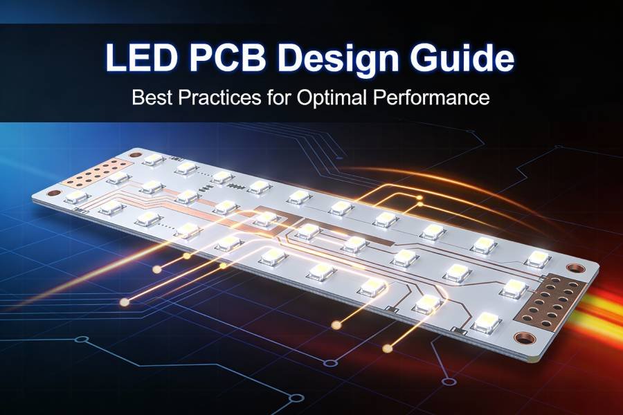
A single design decision—choosing between a standard PCB and an LED PCB—can determine whether your LED product operates flawlessly for 50,000 hours or fails within months. Yet this critical distinction remains poorly understood, even among experienced electronics designers. At first glance, both board types appear similar: copper traces on insulating substrates with solder mask and silkscreen. Look deeper, however, and you’ll find fundamental engineering differences that make each suited to entirely different applications.
The confusion is understandable. Standard PCBs have dominated electronics manufacturing for decades, powering everything from smartphones to industrial controllers with proven reliability and economy. When LEDs entered mainstream lighting, many engineers naturally assumed these versatile boards would work equally well for solid-state lighting. The result? Countless LED products plagued by premature failures, color shifts, reduced brightness, and warranty claims—all stemming from inadequate thermal management inherent to standard PCB construction.
LED technology revolutionized lighting, but it also introduced thermal challenges unprecedented in traditional electronics. A single 3-watt LED generates as much heat per square inch as many complete circuit boards. Standard PCBs, optimized for general electronics where heat generation is modest, simply cannot dissipate LED thermal loads effectively. Enter LED PCBs—specialized boards engineered specifically to handle the unique demands of high-power solid-state lighting.
This comprehensive 2026 guide examines ten fundamental differences between LED PCBs and standard PCBs, covering materials, thermal performance, manufacturing processes, costs, and application suitability. Whether you’re designing your first LED product, troubleshooting premature failures, or optimizing an existing design, understanding these distinctions enables informed decisions that improve performance, extend lifespan, and reduce total cost of ownership.
What is a Standard PCB?
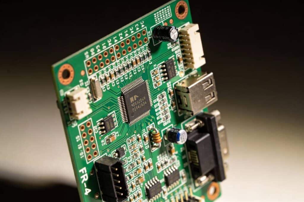
Standard PCBs (Printed Circuit Boards), also called conventional PCBs or FR4 boards, serve as the foundation for general electronics across virtually every industry. These versatile boards provide mechanical support and electrical connections for components ranging from tiny resistors to complex microprocessors, enabling the electronic devices we use daily.
Core Characteristics:
The typical standard PCB consists of a FR4 substrate—a composite material made from woven fiberglass cloth impregnated with flame-retardant epoxy resin. This material earned its “FR4” designation from its fire-resistance rating (Flame Retardant grade 4), making it safe for electronic applications where heat and electrical sparks pose fire risks.
The layered construction includes:
- FR4 Core Material: Fiberglass-reinforced epoxy providing structural integrity and electrical insulation
- Copper Layers: Thin copper foil (typically 1-2oz, or 35-70μm thick) laminated to the substrate surface, etched into circuit traces and pads
- Solder Mask: Protective polymer coating (usually green) covering copper traces while leaving pads exposed
- Silkscreen: White ink printing component designators, logos, and manufacturing information
Standard PCB Applications:
Standard PCBs dominate electronics manufacturing due to their versatility and economy:
- Computer and Communications: Motherboards, network cards, routers, smartphones, tablets, and virtually all computing devices rely on multi-layer FR4 PCBs for complex circuit routing.
- Consumer Electronics: Televisions, audio equipment, gaming consoles, home appliances, and remote controls use standard PCBs for control circuitry and signal processing.
- Industrial Control Systems: PLCs (Programmable Logic Controllers), motor drives, sensors, and automation equipment leverage FR4’s electrical properties and reliability.
- Automotive Electronics: Engine control units, infotainment systems, sensor modules, and most vehicle electronics use standard PCBs—though not typically for high-power LED lighting.
Industry Standards:
Standard PCB manufacturing adheres to established IPC (Institute for Printed Circuits) specifications:
- IPC-2221: Generic standard for PCB design
- IPC-6012: Qualification and performance specification for rigid PCBs
- IPC-A-600: Acceptability criteria for printed boards
These standards ensure consistent quality, reliability, and interoperability across the global electronics supply chain. Thousands of PCB manufacturers worldwide produce standard FR4 boards, creating a highly competitive market with rapid turnaround times and commodity pricing.
Key Advantages:
Standard PCBs excel in general electronics due to:
- Low Cost: FR4 is inexpensive and production is highly automated
- Design Flexibility: Supports complex multi-layer designs (4-20+ layers)
- Universal Availability: Manufactured globally with short lead times
- Excellent Electrical Properties: Superior insulation and controlled impedance
- Proven Reliability: Decades of established performance data
However, these advantages come with a critical limitation: poor thermal conductivity. With heat dissipation rated at just 0.3-0.4 W/mK, standard FR4 PCBs struggle when components generate significant heat—particularly LEDs operating at medium to high power levels.
What is an LED PCB?
LED PCBs represent a specialized category of printed circuit boards engineered specifically to address the thermal management challenges inherent to solid-state lighting. Unlike standard PCBs optimized for general electronics, LED PCBs prioritize heat dissipation above all other considerations, recognizing that LED performance and longevity depend critically on maintaining low operating temperatures.
Why LEDs Demand Specialized PCBs:
Light Emitting Diodes generate substantial heat as an unavoidable byproduct of light production. A typical high-power LED converts only 30-40% of input electrical energy into visible light—the remaining 60-70% becomes heat that must be removed from the LED junction. Without effective thermal management:
- Light Output Drops: LED brightness decreases as junction temperature rises
- Color Shifts: Wavelength changes with temperature, affecting color consistency
- Lifespan Plummets: Every 10°C increase can cut LED life expectancy by half
- Catastrophic Failure: Excessive heat can permanently damage LED semiconductor dies
Standard PCBs with thermal conductivity of 0.3-0.4 W/mK cannot adequately dissipate this heat, leading to junction temperatures exceeding safe operating limits. LED PCBs solve this problem through specialized construction.
LED PCB Structure:
LED PCBs typically employ a metal core substrate that fundamentally changes the thermal equation:
Layer 1 – Metal Base (1.0-3.0mm thick):
- Aluminum, copper, or ceramic base material
- Acts as integrated heat spreader and structural support
- Thermal conductivity: 120-400 W/mK (base material)
- Provides mechanical rigidity and heat sink attachment point
Layer 2 – Dielectric Layer (50-200μm thin):
- Thermally conductive but electrically insulating material
- Bonds circuit layer to metal base
- Thermal conductivity: 1-180 W/mK (through-layer)
- Critical to overall thermal performance
Layer 3 – Copper Circuit Layer (35-140μm):
- Standard copper foil etched into traces and LED mounting pads
- Typically thicker than standard PCB copper for better heat spreading
- Direct thermal contact with LEDs
- Solder mask and silkscreen on top surface
This three-layer construction creates a direct thermal pathway: heat flows from LED junction → through LED package → into copper circuit layer → through thermally conductive dielectric → into metal base → distributed across large area for dissipation.
Common LED PCB Types:
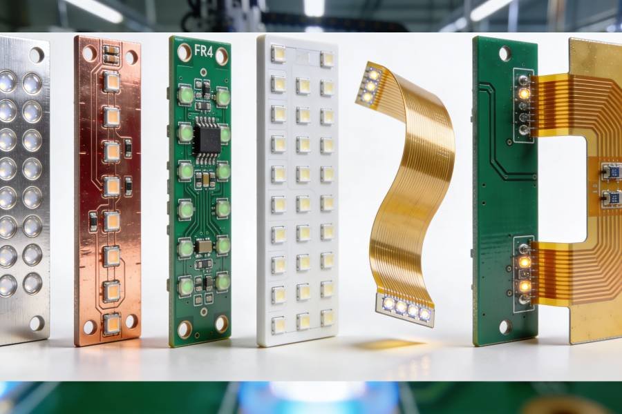
LED PCBs come in several substrate variations, each optimized for different performance and cost targets:
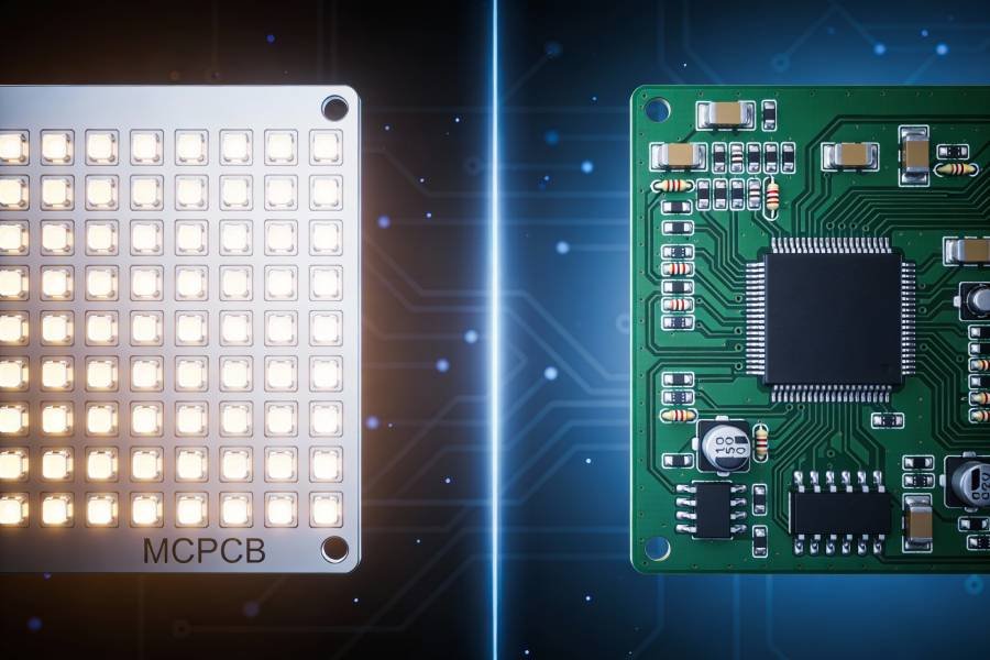
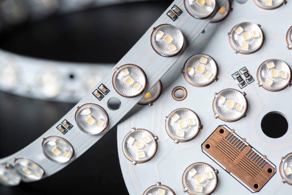
- Aluminum LED PCB (MCPCB): Most common, balancing good thermal performance (1-2 W/mK through dielectric) with reasonable cost. Suitable for most commercial LED applications.
- Copper Core LED PCB: Premium thermal performance (3-8 W/mK) for high-power applications. Costs 2-3x more than aluminum but handles extreme power densities.
- Ceramic LED PCB: Ultimate performance (20-180 W/mK depending on ceramic type) for mission-critical applications. Very expensive but offers unmatched reliability.
- Flexible LED PCB: Specialized polyimide-based flexible circuits for conformable LED applications. Limited thermal performance but enables unique form factors.
- Hybrid LED PCB: Combines metal core LED zones with FR4 control circuitry zones on single assembly, optimizing cost and performance.
For detailed comparison of all LED PCB substrate types, see our comprehensive guide: 6 Types of LED PCB Boards.
LED PCB Applications:
LED PCBs enable reliable operation in demanding lighting applications:
- Commercial and Industrial Lighting: LED panels, high-bay fixtures, street lights, and professional lighting systems requiring long operational life and consistent performance.
- Automotive LED Lighting: Headlights, taillights, daytime running lights, and interior lighting where vibration, temperature extremes, and reliability are critical.
- Consumer LED Products: LED bulbs, downlights, track lighting, and home lighting products seeking competitive lifespan and light quality.
- Display Backlighting: LED backlights for televisions, monitors, signage, and displays requiring uniform brightness and color temperature.
- Specialty Applications: Medical lighting, aerospace illumination, UV curing systems, and any application where LED thermal management is paramount.
The Fundamental Difference:
While standard PCBs treat heat as an unwelcome byproduct to be tolerated, LED PCBs engineer thermal pathways as intentionally as electrical circuits. This philosophical difference—recognizing thermal management as a primary design objective rather than an afterthought—separates successful LED products from problematic ones.
Understanding this distinction leads us to examine the specific engineering differences that make LED PCBs superior for solid-state lighting applications while standard PCBs remain optimal for general electronics.
Key Differences Between LED PCB and Standard PCB
The distinction between LED PCBs and standard PCBs extends far beyond simply using different base materials. Ten fundamental engineering differences affect performance, cost, manufacturability, and application suitability. Let’s examine each in detail.
1. Base Material and Substrate Composition
The substrate—the foundation upon which all circuits are built—represents the most visible and consequential difference between these PCB types.
Standard PCB Substrate:
FR4 Fiberglass Epoxy Resin dominates standard PCB construction. This composite material layers woven fiberglass cloth with flame-retardant epoxy resin, creating a rigid, electrically insulating substrate with excellent mechanical properties.
Key Properties:
- Composition: Woven fiberglass fabric + epoxy resin binder
- Thermal Conductivity: 0.3-0.4 W/mK (extremely poor heat conductor)
- Dielectric Constant: 4.2-4.8 @ 1MHz (good for RF applications)
- Glass Transition Temperature (Tg): 130-180°C depending on grade
- Cost: Very economical, commodity material
- Availability: Universal, every PCB manufacturer stocks FR4
FR4’s molecular structure prioritizes electrical insulation and mechanical strength over thermal conductivity. The epoxy resin and glass fibers create excellent barriers to electrical current flow—but these same properties also block heat flow, trapping thermal energy in the substrate.
Why FR4 Works for General Electronics:
Most electronic components generate modest heat that copper traces and occasional thermal vias can manage adequately. Microprocessors might dissipate significant power, but they use dedicated heat sinks mechanically attached with thermal interface materials. The PCB itself doesn’t need exceptional thermal conductivity because it’s not the primary thermal pathway.
LED PCB Substrate:
Metal Core Substrates flip the priority from electrical insulation to thermal conductivity while maintaining sufficient electrical isolation through specialized dielectric layers.
Aluminum Base (Most Common):
- Composition: 5052, 6061, or 1100 aluminum alloy
- Thermal Conductivity: 120-180 W/mK (base material), 1-2 W/mK (through dielectric)
- Weight: 2.7 g/cm³ (lightweight metal)
- Cost: Moderate premium over FR4
- Availability: Widely available from LED PCB specialists
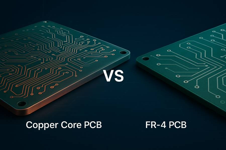
Copper Base (High Performance):
- Composition: 99.9%+ pure copper
- Thermal Conductivity: 385-400 W/mK (base material), 3-8 W/mK (through dielectric)
- Weight: 8.96 g/cm³ (significantly heavier)
- Cost: 2-3x aluminum pricing
- Availability: Fewer suppliers, longer lead times
Ceramic Base (Ultimate Performance):
- Composition: Aluminum oxide (Al₂O₃) or aluminum nitride (AlN)
- Thermal Conductivity: 20-180 W/mK (through substrate)
- Weight: 3.3-3.9 g/cm³
- Cost: 5-20x aluminum pricing
- Availability: Specialized manufacturers only
The Dielectric Layer—The Critical Innovation:
Metal cores conduct heat excellently but also conduct electricity, which would short-circuit the copper traces. The breakthrough enabling LED PCBs is the thermally conductive dielectric layer—a thin (50-200μm) insulating material that blocks electrical current while allowing heat to pass through.
This specialized dielectric uses ceramic-filled polymers or other engineered materials to achieve thermal conductivity 3-10 times higher than FR4 while maintaining electrical isolation exceeding 3000V breakdown voltage. It’s this layer that determines overall LED PCB thermal performance—not just the base material.
Material Selection Impact:
Choosing aluminum versus copper versus ceramic fundamentally determines:
- Maximum LED power density supported
- Product cost and competitiveness
- Manufacturing complexity and lead time
- Expected LED lifespan and reliability
- Heat sink requirements and size
- Total system weight and form factor
2. Thermal Management Capability
Thermal performance—the ability to conduct heat away from components and dissipate it effectively—represents the defining functional difference between LED PCBs and standard PCBs.
Standard PCB Thermal Management:
Standard FR4 PCBs were never designed to be thermal managers. Their thermal conductivity of 0.3-0.4 W/mK makes FR4 essentially a thermal insulator rather than conductor. To put this in perspective, FR4 conducts heat only slightly better than wood or plastic.
Heat Dissipation Mechanisms in Standard PCBs:
Copper Traces as Heat Spreaders:
The copper layers (typically 1-2oz) provide the primary thermal pathway in standard PCBs. Copper’s excellent thermal conductivity (385 W/mK) allows lateral heat spreading across the board surface. Designers maximize copper pour areas around heat-generating components, using solid fills rather than narrow traces.
Thermal Vias:
Vertical thermal vias (copper-plated holes) conduct heat through the FR4 substrate from top copper layer to bottom layer, then to mounting surfaces or external heat sinks. Multiple vias clustered under hot components improve effectiveness, but FR4’s poor conductivity limits via efficiency.
External Cooling Requirements:
Standard PCBs typically require external heat sinks, cooling fans, or thermal interface materials to aluminum chassis for adequate cooling. The PCB itself contributes minimally to thermal management—it’s merely the mounting platform for components and their separate cooling solutions.
Practical Limitations:
- Total power dissipation typically limited to 1-3W per square inch
- Component junction temperatures 20-40°C higher than with metal core
- Hot spots develop around high-power components
- Thermal stress on solder joints from temperature gradients
- Limited effectiveness in enclosed designs without airflow
When Standard PCB Thermal Management Works:
For low-power LEDs (<0.5W each) in well-ventilated enclosures with adequate copper pour and thermal vias, standard FR4 can sometimes suffice. Dashboard indicator LEDs, status lights, and low-intensity displays may operate acceptably on FR4 with careful thermal design and conservative LED drive currents.
However, pushing standard PCBs beyond these limits invites reliability problems. Engineers often discover thermal inadequacy only after field failures accumulate—an expensive lesson.
LED PCB Thermal Management:
LED PCBs engineer thermal pathways as deliberately as electrical circuits, recognizing that controlling heat flow is equally critical to product success.
Integrated Heat Spreading:
The metal core base acts as an integrated heat spreader, conducting heat laterally across the entire board area. A 3-watt LED generating localized heat spreads that thermal energy across hundreds of square centimeters, dramatically reducing peak temperatures.
This heat spreading effect is profound. Instead of a small hot spot under each LED (typical with FR4),
the metal core creates nearly uniform temperature across the entire board. This dramatically reduces thermal stress and improves LED performance consistency.
Direct Thermal Pathway:
LED PCBs create an engineered thermal pathway with minimal thermal resistance:
- LED Junction → Heat generated at semiconductor die
- LED Package → Ceramic or metal-backed LED package conducts to PCB
- Copper Pads → Thick copper (2-3oz) spreads heat locally
- Dielectric Layer → Thermally conductive material transfers heat through
- Metal Base → Aluminum/copper spreads across large area
- Heat Sink Interface → Optional external heat sink attachment
Each step is optimized for low thermal resistance, creating total junction-to-ambient thermal resistance 50-80% lower than equivalent FR4 designs.
Power Density Capability:
The superior thermal management enables dramatically higher power densities:
| LED Power per Component | Standard FR4 PCB | Aluminum LED PCB | Copper LED PCB |
|---|---|---|---|
| 0.5W LED | Marginal | Excellent | Overkill |
| 1W LED | Poor/Unreliable | Good | Excellent |
| 3W LED | Unworkable | Good | Excellent |
| 5W LED | Impossible | Marginal | Good |
| 10W+ LED | Impossible | Impossible | Marginal/Poor |
Thermal Performance Metrics:
Thermal Resistance (junction-to-ambient):
- Standard FR4: 15-40°C/W typical
- Aluminum LED PCB: 5-15°C/W typical
- Copper LED PCB: 3-8°C/W typical
This means for every watt of LED power, junction temperature rises 15-40°C above ambient on FR4, but only 3-15°C on metal core LED PCBs—a difference that often determines whether LEDs last 10,000 or 50,000+ hours.
Heat Sink Integration:
LED PCBs often function as integrated heat sinks, eliminating separate heat sink components. The metal base itself dissipates heat through:
- Surface Area: Large board spreads heat for convection/radiation
- Direct Mounting: PCB mounts directly to aluminum chassis or housing
- Thermal Interface: Minimal TIM (thermal interface material) improves contact
For extreme power levels, LED PCBs still benefit from external heat sinks, but the PCB itself provides substantial thermal management rather than simply passing heat through to external coolers.
For detailed thermal design guidelines, see our comprehensive guide: Thermal Management in LED PCB.
3. Layer Structure and Construction Complexity
The internal architecture of PCBs—how layers stack, interconnect, and route signals—differs dramatically between standard and LED boards, affecting design complexity and manufacturing approaches.
Standard PCB Layer Architecture:
Standard PCBs excel at supporting complex multi-layer constructions enabling sophisticated circuit routing.
Layer Count Capabilities:
- Single-Sided: Component and traces on one side only (rare today)
- Double-Sided: Copper layers on both sides with through-hole vias
- Multi-Layer (4-20+ layers): Multiple copper layers laminated with FR4 cores
Consumer electronics routinely use 4-6 layer boards, computers employ 8-12 layers, and complex telecommunications equipment may exceed 20 layers. This enables:
Dense Circuit Routing:
Multiple signal layers allow crossing traces without interference. Ground and power planes provide clean electrical distribution. Impedance-controlled traces for high-speed signals. Complex circuitry fits in compact form factors.
Via Technologies:
- Through-Hole Vias: Drill through entire board, plate with copper
- Blind Vias: Connect outer layer to internal layer, don’t traverse board
- Buried Vias: Connect internal layers only, invisible from outside
- Micro Vias: Laser-drilled small vias for high-density interconnects
These via options enable flexible routing in three dimensions, solving complex interconnection challenges.
Manufacturing Advantages:
Standard PCB layer stack-up fabrication is highly automated and standardized:
- Pre-preg materials bond layers together under heat and pressure
- Registration alignment ensures layer-to-layer accuracy
- Sequential lamination builds multi-layer boards systematically
- Well-established processes with high yields and low costs
LED PCB Layer Limitations:
LED PCBs sacrifice layer complexity for thermal performance, typically remaining single or double-sided.
Typical LED PCB Construction:
Single-Sided (Most Common):
- Metal base layer (aluminum/copper)
- Dielectric layer
- Single copper circuit layer on top
- All components mount on top side
- Simplest, most cost-effective configuration
Double-Sided (Less Common):
- Copper circuit layer on both sides of dielectric
- Metal base remains single solid layer
- Through vias require drilling through metal and dielectric
- More expensive and complex manufacturing
- Used when both sides need circuits
Multi-Layer Metal Core (Rare/Expensive):
- Attempting 4+ layer constructions with metal cores becomes extremely complex
- Thermal vias through metal cores require specialized drilling
- Registration accuracy challenges with dissimilar materials
- Very few manufacturers capable
- Cost multiplies dramatically
Why Layer Limitation Matters Less:
LED applications typically have simpler circuit requirements:
- LEDs connect in series/parallel strings (simple routing)
- LED drivers are separate components or boards
- Control signals are low-speed (no high-frequency concerns)
- Power distribution is straightforward
- Component count is moderate
The thermal performance gained from metal core construction far outweighs any disadvantage from limited layer count for the vast majority of LED applications.
Thermal Via Considerations:
Creating thermal vias through metal core bases presents unique challenges:
- Standard drill bits wear rapidly on aluminum/copper
- Special tooling and processes required
- Vias must be filled or capped to maintain electrical isolation
- More expensive than standard via processing
Many LED PCB designs avoid through-vias entirely, keeping all circuitry on the top copper layer and relying on the metal base for thermal spreading rather than vertical heat conduction.
4. Manufacturing Process Differences
How PCBs are fabricated—the equipment, processes, and expertise required—differs substantially between standard and LED boards, affecting lead times, costs, and supplier availability.
Standard PCB Manufacturing:
Standard FR4 PCB fabrication represents one of electronics manufacturing’s most mature, optimized, and automated processes.
Fabrication Sequence:
- Design Input: Gerber files, drill files, fabrication drawings
- Material Preparation: FR4 cores and pre-preg layers cut to size
- Inner Layer Processing: Circuit patterns imaged and etched on cores
- Layer Alignment: Precision alignment and optical registration
- Lamination: Heat and pressure bond layers together
- Drilling: CNC drilling creates via holes
- Plating: Electroless and electrolytic copper plating
- Outer Layer Imaging: Circuit pattern transferred to outer copper
- Etching: Remove unwanted copper, leaving traces and pads
- Solder Mask: Apply protective coating
- Silkscreen: Print component designations
- Surface Finish: HASL, ENIG, OSP, or other finish
- Routing: Cut individual boards from panel
- Testing: Electrical test, visual inspection
- Packaging: Ship to customer
Manufacturing Advantages:
High Automation: Modern PCB factories process FR4 boards with minimal human intervention, using automated optical inspection (AOI), precise CNC equipment, and computer-controlled chemical processing.
Universal Capability: Thousands of PCB manufacturers worldwide can produce standard FR4 boards. This competition drives down costs and reduces lead times. Engineers can source locally, regionally, or internationally based on preferences.
Rapid Turnaround: Quick-turn PCB services deliver prototype quantities in 24-48 hours for simple designs, 3-5 days for complex boards. Standard production runs complete in 1-2 weeks.
Low Setup Costs: Automated processes and high-volume tooling minimize non-recurring engineering (NRE) charges. Many suppliers waive setup fees entirely for production orders.
Mature Quality Control: Decades of refinement have standardized inspection criteria (IPC-A-600), testing methodologies, and acceptance standards. Quality is predictable and consistent.
LED PCB Manufacturing:
LED PCB fabrication requires specialized equipment and processes to handle metal substrates, creating barriers to entry that limit supplier options.
Specialized Processing Requirements:
Metal Substrate Handling:
- Aluminum and copper bases require different cutting, drilling, and routing approaches than FR4
- Heavier materials need robust fixturing and support
- Tool wear is significantly higher (especially with copper)
- Diamond or carbide tooling necessary for long tool life
Dielectric Layer Application:
- Specialized thermally conductive dielectric materials
- Precise thickness control (50-200μm) critical to performance
- Bonding process requires specific temperature/pressure profiles
- Quality control of dielectric integrity essential
Drilling Challenges:
- Drilling through metal cores drastically increases drill bit wear
- Specialized bits and parameters required
- Hole wall quality more difficult to maintain
- Plating through metal-backed holes presents challenges
CTE Mismatch Management:
- Coefficient of thermal expansion differs between copper circuit layer and aluminum/copper base
- Registration and dimensional stability require careful process control
- Layer-to-layer alignment more challenging than FR4
Manufacturing Constraints:
Limited Supplier Base: Only specialized PCB manufacturers possess the equipment and expertise for LED PCB production. This reduces competition and increases lead times.
Longer Lead Times:
- Prototype quantities: 5-10 days typical (vs. 2-3 days for FR4)
- Production quantities: 2-4 weeks typical (vs. 1-2 weeks for FR4)
- Complex designs may extend further
Higher Minimum Quantities: Setup costs and process complexity often result in MOQs (Minimum Order Quantities) of 25-100 pieces for LED PCBs vs. 5-10 for standard PCBs.
Quality Control Specifics: Beyond standard electrical testing, LED PCBs require:
- Thermal resistance testing
- Dielectric breakdown voltage verification
- Adhesion testing (delamination risk)
- Thermal cycling qualification
Cost Implications:
The specialized nature of LED PCB manufacturing translates directly to higher costs:
- Material costs: 2-10x higher than FR4
- Processing costs: 50-200% premium for specialized equipment
- Tooling wear: Higher consumable costs passed to customers
- Lower production volumes: Less economy of scale
However, these costs must be weighed against the total product value. For LED lighting products, the PCB typically represents only 10-20% of total BOM (Bill of Materials). Saving $2 on the PCB while sacrificing LED lifespan from 50,000 hours to 15,000 hours represents false economy.
For LED PCB manufacturing services with expertise across all substrate types, explore our LED PCB Manufacturing Capabilities.
5. Cost Comparison and Economic Considerations
Price differences between standard and LED PCBs significantly impact product economics, but simplistic cost comparisons miss the total cost of ownership picture.
Standard PCB Pricing:
Standard FR4 PCBs have become commodity products with highly competitive pricing:
Prototype Quantities (1-10 boards):
- Simple 2-layer, small size: $5-20 total order
- Complex 4-layer, medium size: $50-150
- Advanced 6+ layer, large size: $200-500
Small Production (50-100 boards):
- Simple designs: $1-3 per board
- Medium complexity: $3-8 per board
- Complex designs: $8-20 per board
Volume Production (1000+ boards):
- Simple designs: $0.10-0.50 per board
- Medium complexity: $0.50-2.00 per board
- Complex designs: $2-5 per board
Factors Affecting FR4 Cost:
- Board size (larger = more expensive)
- Layer count (more layers = higher cost)
- Minimum trace/space (finer = more expensive)
- Surface finish type (ENIG > HASL > OSP)
- Solder mask color (green cheapest, other colors premium)
- Quantity (dramatic price breaks at volume)
LED PCB Pricing:
LED PCBs command premium pricing reflecting specialized materials and manufacturing:
Aluminum LED PCB:
Prototype (5-25 boards):
- Small size (50-100cm²): $15-35 per board
- Medium size (100-200cm²): $25-60 per board
- Large size (200cm²+): $40-100 per board
Production (100-500 boards):
- Small: $6-15 per board
- Medium: $10-25 per board
- Large: $18-45 per board
Volume (1000+ boards):
- Small: $2-8 per board
- Medium: $4-12 per board
- Large: $8-20 per board
Copper Core LED PCB (2-3x aluminum pricing):
- Prototype: $40-120 per board
- Production: $20-60 per board
- Volume: $8-30 per board
Ceramic LED PCB (5-20x aluminum pricing):
- Prototype: $80-300+ per board
- Production: $40-150 per board
- Volume: $20-80 per board
Total Cost of Ownership Analysis:
Focusing solely on PCB unit cost ignores the broader economic picture:
Example: LED Downlight Product
Scenario A: Standard FR4 PCB
- PCB cost: $1.50
- LED lifespan: 15,000 hours (thermal stress)
- Warranty rate: 8% (premature failures)
- Customer satisfaction: Lower (dimming, failures)
Scenario B: Aluminum LED PCB
- PCB cost: $4.50 (+$3.00 premium)
- LED lifespan: 50,000 hours (proper thermal management)
- Warranty rate: 2% (reliable operation)
- Customer satisfaction: Higher (consistent performance)
Economic Impact Per 10,000 Units:
PCB Cost Difference:
- Additional PCB cost: $30,000
Warranty Cost Savings:
- FR4 warranty (8% x $25 avg cost): $20,000
- Aluminum warranty (2% x $25 avg cost): $5,000
- Savings: $15,000
Brand Value & Reputation:
- Fewer customer complaints
- Lower return rates
- Better online reviews
- Repeat purchase likelihood
Net Economic Result:
Even with $30K higher PCB costs, warranty savings of $15K plus intangible brand benefits often justify the LED PCB premium—particularly in competitive markets where product quality differentiates brands.
When Cost Optimization Favors Each Type:
Choose Standard PCB When:
- LED power definitively stays below 0.3W per component
- Application is cost-critical (toys, promotional items)
- Short product lifespan acceptable (disposable products)
- Operating environment is cool with good airflow
Choose LED PCB When:
- LED power exceeds 0.5W per component
- Product carries warranty obligations
- Brand reputation depends on reliability
- Total cost of ownership matters more than initial cost
- Professional or commercial application
6. Electrical Properties and Signal Integrity
While thermal performance dominates LED PCB design considerations, electrical characteristics still matter—particularly for complex LED systems integrating control electronics.
Standard PCB Electrical Excellence:
FR4’s molecular structure provides outstanding electrical insulation and controlled electrical properties that have made it the substrate of choice for high-frequency and precision electronics.
Key Electrical Parameters:
Dielectric Constant (Dk):
- FR4: 4.2-4.8 @ 1MHz (stable and predictable)
- Low variation across frequency ranges
- Enables controlled impedance design
- Suitable for high-speed signals up to several GHz
Dielectric Loss Tangent:
- FR4: 0.02 typical (low signal loss)
- Acceptable for most digital and analog circuits
- Minimal signal degradation over trace lengths
Volume Resistivity:
- FR4: >10^14 Ω·cm (excellent insulation)
- Prevents leakage currents between traces
- Maintains isolation even in humid environments
Dielectric Breakdown Strength:
- FR4: 20-40 kV/mm
- Safely handles high voltages
- Provides protection against voltage spikes
Applications Leveraging FR4 Electrical Properties:
These characteristics make standard PCBs ideal for:
- High-speed digital circuits (computers, communications)
- RF and microwave applications (controlled impedance)
- Precision analog circuits (low leakage, stable characteristics)
- High-voltage applications (excellent breakdown strength)
LED PCB Electrical Considerations:
LED PCBs introduce the metal core base, which fundamentally changes the electrical environment despite the dielectric isolation layer.
Dielectric Layer Performance:
The thermally conductive dielectric in LED PCBs must balance thermal conductivity with electrical insulation:
Thermal vs. Electrical Trade-Off:
- Higher thermal conductivity often means higher dielectric constant
- Ceramic-filled polymers increase thermal transfer but affect electrical properties
- Thinner dielectric improves thermal performance but reduces breakdown voltage
Typical LED PCB Electrical Properties:
Dielectric Constant:
- 3.5-6.0 typical (varies by dielectric material)
- Higher and less controlled than FR4
- Less suitable for impedance-controlled traces
Dielectric Breakdown Voltage:
- 3000-5000V typical
- Adequate for LED applications (typically 12-48V DC)
- Critical safety parameter for UL/CE certification
Volume Resistivity:
10^12 Ω·cm minimum
- Adequate electrical isolation
- Quality control critical to prevent defects
Capacitance Considerations:
The metal base acts as a large ground plane, creating distributed capacitance between circuit traces and the base. This generally isn’t problematic for LED applications but can affect:
- High-frequency switching noise
- EMI/EMC characteristics
- Signal integrity for control lines
Grounding Strategy:
The metal base in LED PCBs requires careful grounding consideration:
Electrically Grounded Base:
- Connect metal base to circuit ground
- Provides EMI shielding
- Improves thermal performance (direct contact to chassis)
- Requires careful insulation from line voltage
Floating Base:
- Leave metal base electrically isolated
- Safer for high-voltage LED drivers
- Slightly worse thermal performance
- Requires thermal interface with proper insulation
Design Implications:
For Standard PCB Designs:
- Full freedom for high-speed digital design
- Controlled impedance traces straightforward
- Minimal constraints on signal routing
- Suitable for integrating complex control electronics
For LED PCB Designs:
- Focus on power distribution and LED connections
- Avoid high-speed signals if possible
- Keep control signals low-frequency
- Consider hybrid designs for complex electronics + LEDs
When Electrical Properties Matter:
LED applications rarely push electrical limits:
- Most operate on low-voltage DC (12V, 24V, 48V)
- Signal frequencies are modest (PWM dimming at kHz range)
- Current levels are straightforward to route
- Impedance control rarely needed
However, smart LED systems integrating wireless modules, microcontrollers, or high-speed communications may benefit from hybrid approaches using FR4 for digital circuitry and metal core sections only for LED mounting. See our guide on Hybrid LED PCB Design for complex applications.
7. Mechanical Properties and Physical Characteristics
Physical attributes—weight, rigidity, thickness, and mechanical strength—create practical differences affecting product design, assembly, and durability.
Standard PCB Mechanical Profile:
FR4 PCBs offer versatility in form factor and mechanical characteristics suited to general electronics packaging.
Thickness Options:
- Ultra-thin: 0.4mm, 0.6mm (flexible phones, wearables)
- Standard: 0.8mm, 1.0mm, 1.6mm (most common)
- Thick: 2.0mm, 2.4mm, 3.2mm (high-current, mechanical strength)
Weight Characteristics:
- FR4 density: ~1.85 g/cm³
- Lightweight compared to metal substrates
- Minimal contribution to product weight
- Important for portable electronics, aerospace
Mechanical Strength:
- Flexural strength: 415 MPa (strong enough for most applications)
- Can be fragile when thin or with many holes/cutouts
- Susceptible to cracking from mechanical shock if unsupported
- Bending can crack solder joints or traces
Form Factor Flexibility:
- Can be manufactured in virtually any shape
- Complex cutouts, slots, and edge features
- Flexible PCB variants enable bendable/foldable designs
- Rigid-flex combinations for three-dimensional assemblies
CTE (Coefficient of Thermal Expansion):
- In-plane (X-Y): 14-17 ppm/°C
- Through-plane (Z-axis): 50-70 ppm/°C
- Z-axis CTE can cause via reliability issues with temperature cycling
- Generally matches component CTEs reasonably well
LED PCB Mechanical Characteristics:
Metal core construction creates fundamentally different mechanical properties affecting product design and assembly.
Thickness Reality:
- Typical: 1.0mm, 1.2mm, 1.5mm, 2.0mm, 3.0mm
- Thin options limited by metal base requirements
- Cannot achieve 0.4-0.6mm thicknesses of FR4
- Thickness driven by mechanical and thermal needs
Weight Considerations:
Aluminum LED PCB:
- Aluminum density: 2.7 g/cm³
- Slightly heavier than FR4 of equivalent thickness
- Still relatively lightweight
- Acceptable for most applications
Copper Core LED PCB:
- Copper density: 8.96 g/cm³
- Significantly heavier than aluminum (3.3x)
- Weight becomes consideration in automotive, aerospace
- Mounting structures must accommodate increased weight
Ceramic LED PCB:
- Ceramic density: 3.3-3.9 g/cm³
- Heavier than aluminum, lighter than copper
- Brittle material requires careful handling
Mechanical Strength and Rigidity:
Advantages of Metal Core:
- Excellent mechanical rigidity
- Resists bending and warping
- Protects components during handling and assembly
- Withstands mechanical stress better than thin FR4
- Good vibration resistance (important for automotive)
Limitations:
- Cannot flex or bend (rigid only)
- Brittle ceramic substrates can crack from impact
- Heavier weight may stress mounting points
- More difficult to cut or modify after manufacturing
CTE Matching:
Aluminum:
- CTE: 23-26 ppm/°C
- Higher than FR4 and many components
- Can create thermal stress during temperature cycling
- Generally acceptable for LED applications
Copper:
- CTE: 17-18 ppm/°C
- Better match to components than aluminum
- Reduced thermal stress on solder joints
- One advantage justifying copper’s cost in thermal cycling environments
Ceramic:
- CTE: 4-7 ppm/°C
- Excellent match to LED dies and many components
- Minimizes thermal stress
- Critical advantage for high-reliability applications
Assembly Considerations:
Standard PCB Assembly:
- Standard pick-and-place equipment
- Lightweight allows delicate handling
- Easy depanelization (breaking apart panels)
- Standard fixturing and support
LED PCB Assembly:
- Heavier boards may require modified fixtures
- Metal cores conduct heat during soldering (affects reflow profiles)
- Cutting/routing creates metal shavings requiring cleanup
- More robust support needed during assembly
Product Design Impact:
The mechanical differences influence:
- Mounting methods: LED PCBs often mount directly to chassis/heat sinks
- Enclosure design: Must accommodate thickness and weight
- Thermal interface: Metal backing facilitates heat transfer to housing
- Vibration resilience: Metal rigidity benefits automotive/industrial applications
8. Design Complexity and Engineering Requirements
The engineering effort, expertise, and tools required for successful PCB design differ significantly between standard and LED boards.
Standard PCB Design Maturity:
Decades of standard PCB use have created mature design ecosystems with extensive resources, tools, and established best practices.
Design Tools and Resources:
Ubiquitous CAD Software:
- Altium Designer, Eagle (Autodesk), KiCad (free/open-source)
- OrCAD, PADS, Mentor Graphics
- Extensive component libraries
- Auto-routing capabilities
- DRC (Design Rule Check) automation
- Gerber output standardization
Design Rule Repositories:
- IPC standards widely documented
- Manufacturer design guides readily available
- Online calculators for trace width, via sizing
- Stack-up tools for impedance control
Engineering Knowledge Base:
- Thousands of published design guides
- University courses teaching PCB design
- Online communities (EEVblog, Reddit, forums)
- Extensive troubleshooting resources
Design Complexity Support:
Standard PCBs handle complex requirements efficiently:
- High-density routing: Automatic optimization algorithms
- Multi-board systems: Defined connector standards
- Signal integrity: Built-in simulation tools
- Power integrity: Analysis integrated into design flow
- EMC/EMI: Design rules and shielding strategies well-documented
Skill Level Required:
- Entry-level: Simple 2-layer boards achievable by hobbyists
- Intermediate: 4-6 layer boards with modest complexity
- Advanced: High-speed digital, RF, or complex multi-layer designs
The learning curve is well-supported with abundant educational materials.
LED PCB Design Considerations:
LED PCB design adds thermal engineering as a primary discipline alongside electrical design, requiring specialized knowledge.
Thermal Design as Primary Focus:
Unlike standard PCB design where thermal concerns are secondary, LED PCB engineers must:
Calculate Heat Dissipation:
- LED power consumption and efficiency
- Junction temperature targets
- Thermal resistance budgets
- Heat spreading requirements
Thermal Simulation:
- Finite element analysis (FEA) tools
- CFD (Computational Fluid Dynamics) for airflow
- Transient thermal analysis for dynamic conditions
- Steady-state temperature predictions
Material Selection Expertise:
- Understand thermal conductivity trade-offs
- Select appropriate substrate for application
- Specify dielectric layer properties
- Plan for thermal interface materials
Design Guidelines Specific to LED PCBs:
Copper Pour Optimization:
- Maximize copper area under and around LEDs
- Thicker copper (2-3oz) for better heat spreading
- Balance electrical requirements with thermal needs
LED Placement Strategy:
- Distribute heat-generating LEDs evenly
- Avoid clustering high-power LEDs
- Consider thermal interaction between nearby LEDs
- Plan for optical requirements (light distribution)
Thermal Via Design:
- Calculate number and size of thermal vias
- Position vias strategically under LED pads
- Understand via thermal resistance contribution
- Plan for via filling or capping if required
Heat Sink Integration:
- Design for mechanical attachment
- Specify thermal interface materials
- Plan mounting hole patterns
- Consider assembly sequence
Specialized Design Tools:
Thermal Simulation Software:
- ANSYS Icepak, FloTHERM, SolidWorks Flow Simulation
- Specialized LED thermal modeling tools
- Requires additional software licenses and expertise
- Significantly extends design time vs. standard PCB
LED-Specific CAD Libraries:
- LED component footprints with thermal pads
- Metal core PCB layer stack-ups
- Manufacturer-specific design rules for LED PCBs
Design Rule Differences:
LED PCB manufacturers have unique requirements:
- Minimum dielectric thickness specifications
- Copper weight options and constraints
- Via drilling limitations through metal cores
- Edge clearance requirements for metal base
- Surface finish compatibility with assembly
Skill Level and Learning Curve:
Additional Expertise Required:
- Thermal engineering fundamentals
- Heat transfer principles
- LED characteristics and specifications
- Familiarity with metal core PCB constraints
- Understanding of thermal testing methods
This specialized knowledge creates barriers to entry. Many electrical engineers excel at circuit design but lack thermal engineering background, necessitating either training or collaboration with thermal specialists.
Design Iteration Considerations:
Standard PCB:
- Quick design iterations (hours to days)
- Rapid prototyping (2-7 days)
- Easy to test multiple design variations
- Low cost for design exploration
LED PCB:
- Thermal simulations add days to design cycle
- Prototype lead times longer (1-2 weeks)
- Higher prototype costs limit iteration
- Thermal testing requires specialized equipment
The extended design cycle and iteration costs make getting LED PCB designs right the first time more critical, increasing pressure on engineering teams.
Design Support Services:
Recognizing these challenges, many LED PCB manufacturers offer design assistance:
- DFM (Design for Manufacturing) review
- Thermal analysis and simulation
- Material selection guidance
- Optimization recommendations
9. Application Suitability and Use Cases
Understanding which PCB type suits specific applications prevents costly mistakes and ensures optimal product performance.
Standard PCB Applications:
FR4 boards dominate general electronics where thermal demands remain modest and complex circuitry is common.
Ideal Standard PCB Applications:
Computing and Data Processing:
- Computer motherboards, graphics cards, network switches
- Servers, storage systems, telecommunications equipment
- Complex circuits with hundreds of components
- High-speed digital signals requiring impedance control
Consumer Electronics:
- Smartphones, tablets, laptops (complex multi-layer)
- Audio equipment, gaming consoles, smart home devices
- Remote controls, small appliances, toys
- Any product with complex control electronics
Industrial Control:
- PLC modules, motor controllers, sensor interfaces
- Building automation, HVAC controls
- Industrial IoT devices, data acquisition systems
- Process control and monitoring equipment
Automotive Electronics (Non-Lighting):
- Engine control units, transmission controllers
- Infotainment systems, navigation, connectivity modules
- Sensor modules, camera systems, ADAS electronics
- Body control, comfort, and convenience systems
Medical Devices (Non-Illumination):
- Patient monitoring equipment
- Diagnostic devices and analyzers
- Portable medical electronics
- Therapeutic devices
Low-Power LED Applications:
Standard PCBs can work for LEDs when power stays minimal:
- Indicator LEDs (<100mW): Status lights, power indicators, diagnostic LEDs
- Low-intensity displays: 7-segment displays, dot-matrix signs, small LED arrays
- Backlighting (low power): Keypad backlights, button illumination, small display backlights
- Decorative lighting (low power): Holiday lights, ambient mood lighting using many small LEDs
Key Constraint: Total LED power dissipation per board area must remain low (typically <2-3W per 100cm²) to avoid thermal issues.
LED PCB Applications:
Metal core LED PCBs enable reliable operation wherever LEDs generate significant heat or long lifespan is required.
Optimal LED PCB Applications:
Commercial and Architectural Lighting:
- LED downlights, track lighting, panel lights
- Office lighting, retail illumination
- Street lights, parking lot lighting, area lighting
- Landscape and architectural accent lighting
Industrial Lighting:
- High-bay fixtures for warehouses and factories
- Task lighting for workstations
- Hazardous location lighting (explosion-proof)
- Cold storage and extreme environment lighting
Automotive LED Lighting:
- Headlights: High-power LEDs requiring copper or aluminum substrates
- Taillights and brake lights: Aluminum LED PCBs for reliability
- Daytime running lights (DRL): Medium-power LEDs on aluminum
- Interior ambient lighting: Flexible or standard aluminum LED PCBs
Consumer LED Products:
- LED bulbs for home use (A19, PAR, MR16 formats)
- Residential downlights and recessed lighting
- Under-cabinet lighting, strip lighting
- Table lamps, floor lamps, decorative fixtures
Display and Signage:
- LED video display panels (indoor and outdoor)
- Digital signage and menu boards
- Scoreboards and information displays
- Backlighting for large-format displays
Specialty Applications:
- Stage and entertainment lighting: High-power theatrical fixtures
- Horticultural lighting: LED grow lights for agriculture
- UV curing systems: High-intensity UV LED arrays
- Medical lighting: Surgical lights, examination lights
- Aerospace lighting: Aircraft interior and exterior lighting
Power Level Guidelines:
| LED Power per Component | Recommended PCB Type |
|---|---|
| <0.3W | Standard FR4 acceptable |
| 0.3-0.5W | FR4 marginal, aluminum preferred |
| 0.5-3W | Aluminum LED PCB required |
| 3-10W | Aluminum or copper core |
| 10W+ | Copper core or ceramic |
10. Heat Sink Integration and Thermal Interface
The final major difference concerns how PCBs interface with thermal management systems and whether external heat sinks are necessary.
Standard PCB Heat Sink Requirements:
FR4’s poor thermal conductivity means heat must be removed through external thermal pathways, not through the PCB itself.
External Heat Sink Necessity:
For any component generating significant heat (>1W), standard PCBs require:
Mechanical Heat Sink Attachment:
- Component-mounted heat sinks clipped or glued to chip packages
- Thermal adhesive or phase-change materials between component and heat sink
- Heat sink fins or extrusions dissipate heat to air
- No thermal benefit from PCB itself
Chassis Mounting:
- High-power components may mount to metal chassis
- Thermal pads or grease transfer heat through board to chassis
- Board acts as thermal barrier, not thermal pathway
- Requires careful mechanical design
Active Cooling:
- Fans required for higher power densities
- Forced air cooling over heat sinks
- Adds cost, noise, complexity, and failure modes
- Power consumption for fan operation
Assembly Complexity:
External heat sink approaches increase assembly steps:
- Apply thermal interface material
- Position heat sink
- Secure with clips, screws, or adhesive
- Verify thermal contact quality
- Route airflow appropriately
Each step adds cost, time, and potential quality issues.
LED Application Challenges:
For LED arrays on standard FR4:
- Each LED cluster may need individual heat sinks
- Limited space for heat sink attachment
- Thermal interface materials degrade over time
- Difficult to achieve uniform cooling across array
- Total system size increases with external cooling
These challenges make standard PCBs impractical for most LED lighting products beyond low-power indicators.
LED PCB Integrated Thermal Management:
Metal core LED PCBs fundamentally change thermal management by integrating heat spreading into the PCB itself.
PCB as Integrated Heat Spreader:
The metal base serves multiple thermal functions:
Direct Heat Spreading:
- LEDs transfer heat to copper circuit layer
- Heat conducts through thin dielectric (50-200μm)
- Metal base spreads heat across entire board area
- Large surface dissipates heat via convection and radiation
Self-Heat Sinking Capability:
For moderate power levels (10-30W total), LED PCBs can self-cool:
- Large board area (100-300cm²) spreads heat
- Natural convection dissipates 0.5-1.5W per square inch
- No external heat sink required
- Simplified product design
Chassis Integration:
For higher power applications:
Direct Mounting to Chassis:
- Metal base mounts directly to aluminum housing
- Thin thermal pad (0.5-1mm) improves contact
- Housing acts as extended heat sink
- Simple, reliable thermal pathway
Mounting Methods:
- Screws or clips: Mechanical compression ensures contact
- Thermal adhesive: Permanent mounting with good thermal transfer
- Thermal tape: Easy assembly, moderate performance
- No interface material: Direct metal-to-metal (requires flat surfaces)
Thermal Resistance Impact:
The integrated approach dramatically reduces total thermal resistance:
Standard PCB + External Heat Sink:
- LED junction → PCB copper: 2-5°C/W
- Through FR4 substrate: 20-50°C/W (major bottleneck)
- Thermal interface to heat sink: 1-3°C/W
- Heat sink to ambient: 5-15°C/W
- Total: 28-73°C/W
LED PCB Direct Mounted:
- LED junction → PCB copper: 2-5°C/W
- Through dielectric: 3-10°C/W
- Metal base spreading: 1-3°C/W
- Thermal pad to chassis: 0.5-2°C/W
- Chassis to ambient: 3-10°C/W
- Total: 9.5-30°C/W
The 50-70% reduction in thermal resistance translates directly to lower LED junction temperatures and longer lifespan.
External Heat Sink Options:
When required, LED PCBs integrate with external heat sinks more effectively:
Extruded Aluminum Heat Sinks:
- LED PCB mounts to flat heat sink surface
- Large contact area for efficient heat transfer
- Heat sink fins optimize convection
- Common for high-power LED modules
Die-Cast Heat Sink Housings:
- Entire product housing serves as heat sink
- LED PCB mounts inside, transferring heat to walls
- Maximum cooling capacity
- Used for high-power LED bulbs and fixtures
Active Cooling Enhancement:
- Fans can supplement natural cooling when needed
- Much smaller fans required vs. standard PCB approach
- Lower airflow rates sufficient
- Quieter operation possible
Assembly Advantages:
LED PCB thermal integration simplifies manufacturing:
- Fewer assembly steps (no individual component heat sinks)
- Faster assembly time
- More reliable (fewer parts to fail)
- Easier quality control
- Lower total system cost despite higher PCB cost
Design Flexibility:
The integrated thermal approach enables:
- More compact product designs
- Lower profile fixtures
- Passive cooling for many applications
- Simpler mechanical design
- Better aesthetics (no visible external heat sinks)
For comprehensive guidance on LED PCB thermal design and heat sink integration, consult our Why Choose Us page highlighting our thermal engineering expertise.
Detailed Comparison Table: Standard PCB vs LED PCB
The following comprehensive table summarizes all key differences for quick reference:
| Characteristic | Standard PCB (FR4) | LED PCB (Metal Core) |
|---|---|---|
| Base Material | FR4 fiberglass epoxy | Aluminum, copper, or ceramic |
| Thermal Conductivity | 0.3-0.4 W/mK | 1-180 W/mK (depending on type) |
| Primary Purpose | General electronics | LED thermal management |
| Layer Complexity | 1-20+ layers common | Typically 1-2 layers |
| Thickness Range | 0.4-3.2mm | 1.0-3.0mm typical |
| Weight (relative) | Lightweight | Medium to heavy |
| Cost (prototype) | $5-20 per board | $15-100+ per board |
| Cost (volume) | $0.10-5 per board | $2-80+ per board |
| Lead Time | 1-7 days | 5-14 days |
| Supplier Availability | Universal | Specialized manufacturers |
| Design Complexity | Moderate to high | Moderate (thermal focus) |
| Electrical Properties | Excellent (Dk 4.2-4.8) | Good (Dk 3.5-6.0) |
| Heat Dissipation | Poor (requires external cooling) | Excellent (integrated) |
| LED Power Support | <0.5W per LED | 0.5-20W+ per LED |
| Mechanical Rigidity | Moderate | Excellent |
| Flexibility Options | Rigid or flexible | Rigid only |
| Via Technology | Through, blind, buried | Limited by metal core |
| CTE (thermal expansion) | 14-17 ppm/°C (X-Y) | 17-26 ppm/°C (aluminum) |
| Dielectric Strength | 20-40 kV/mm | 3-5 kV/mm (adequate) |
| Manufacturing Automation | Highly automated | Semi-automated |
| Rework Capability | Easy | Difficult |
| Heat Sink Integration | Requires external heat sinks | Integrated or simplified |
| Typical Applications | Computing, consumer electronics, control systems | LED lighting, displays, automotive LED |
| Lifespan Impact | Neutral | Extends LED lifespan 2-5x |
| Design Tools | Universal CAD software | Requires thermal simulation |
| Skill Level Required | Electrical engineering | Electrical + thermal engineering |
| Quality Standards | IPC-6012, IPC-A-600 | Same + thermal testing |
| Environmental Resistance | Good | Excellent |
| Vibration Resistance | Moderate | Excellent |
When to Use Standard PCB for LED Applications
Despite LED PCBs’ advantages, specific scenarios justify using standard FR4 for LED circuits.
Low-Power LED Indicators (<0.3W per LED)
Application Examples:
- Power indicator LEDs on equipment
- Status lights (on/off, charging, error codes)
- Dashboard warning lights
- Diagnostic LEDs on electronics
Why Standard PCB Works:
- Heat generation negligible (<0.3W)
- FR4 thermal limitations irrelevant at these power levels
- Cost savings significant (pennies vs. dollars)
- LED lifespan still exceeds 30,000+ hours
- Integration with control electronics simplified
Design Considerations:
- Use conservative drive currents (10-20mA vs. maximum rated)
- Provide copper pour around LED pads for minor heat spreading
- Ensure adequate ventilation
- Monitor junction temperature during testing
Complex Multi-Function Boards
When circuits include:
- Microcontrollers, processors, or complex digital logic
- Multiple sensors and interfaces
- Wireless communication modules (Wi-Fi, Bluetooth, Zigbee)
- Power supply circuits and voltage regulators
- LEDs as secondary function (indicators, small displays)
Why Standard PCB Makes Sense:
- Multi-layer routing required for complex circuits
- FR4 electrical properties needed for high-speed signals
- LED power remains low due to secondary role
- Single-board solution more cost-effective than hybrid approach
Alternative Approach:
Consider hybrid PCB with FR4 section for electronics and small metal core section for LEDs if thermal management becomes marginal.
Prototype and Development Phase
Early Design Exploration:
- Fast iteration (2-3 day turnaround)
- Low prototype costs enable multiple design variations
- Easy to modify and rework
- Proves circuit functionality before committing to LED PCB
Transition Strategy:
- Prototype on FR4 for circuit validation
- Test thermal performance with target LED drive currents
- Measure junction temperatures under worst-case conditions
- Transition to metal core if temperatures exceed targets
- Re-test on LED PCB prototype before production
This staged approach minimizes development costs while ensuring final product reliability.
Ultra-Cost-Sensitive Applications
Market Segments:
- Promotional products and giveaways
- Low-cost toys and novelty items
- Disposable electronics
- Products with expected short lifespan (<2 years)
When FR4 is Justified:
- Retail price point allows only minimal PCB budget
- Product not expected to last long-term anyway
- Competition demands absolute minimum cost
- Warranty costs acceptable vs. PCB premium
Risk Mitigation:
- Over-size LEDs (under-drive for lower junction temperature)
- Maximize copper pour and thermal vias
- Design for good airflow
- Set realistic expectations for performance and lifespan
Ambient Temperature Controlled Environments
Ideal Conditions:
- Indoor use only in climate-controlled spaces
- Operating temperature: 15-25°C typical
- Good natural or forced air circulation
- No direct sunlight or heat exposure
With favorable ambient conditions, FR4’s thermal limitations matter less. Junction temperatures stay moderate even with limited heat dissipation capability.
Short Duty Cycle Applications
Use Patterns:
- LEDs operate intermittently (< 25% duty cycle)
- Sufficient off-time allows passive cooling
- Peak power higher but average power low
- Junction temperature never reaches steady-state maximum
Examples:
- Camera flash LEDs
- Warning beacons (strobe lights)
- Intermittent indicator lights
- Photographic lighting (short duration)
Thermal mass absorbs heat during short on-periods, dissipating between cycles.
When to Use LED PCB (Metal Core PCB)
LED PCBs become necessary—not just preferable—when thermal demands exceed FR4’s capabilities.
Medium to High-Power LEDs (>0.5W per component)
Once individual LEDs exceed 0.5W, junction temperatures on FR4 typically exceed safe operating limits, making metal core substrates mandatory for reliable operation.
Power Ranges:
- 0.5-3W per LED: Aluminum LED PCB standard choice
- 3-10W per LED: Aluminum or copper depending on density
- 10W+ per LED: Copper core or ceramic required
Commercial and Professional Lighting Products
Product Categories:
- Office LED panels and troffers
- Retail track lighting and spotlights
- Hospitality and restaurant lighting
- Street and parking lot luminaires
Why LED PCB is Mandatory:
- Warranty obligations (typically 3-5 years)
- Continuous operation (8-24 hours daily)
- Professional reliability expectations
- Regulatory compliance requirements (UL, DLC)
- Brand reputation on the line
Failure rates must stay below 1-2% to maintain profitability and reputation.
Automotive LED Lighting
Demanding Environment:
- Temperature extremes: -40°C to +85°C
- Constant vibration and mechanical stress
- High reliability requirements (safety-critical)
- 10-15 year expected vehicle life
- Difficult and expensive to replace
LED PCB Advantages:
- Metal rigidity withstands vibration
- Thermal performance handles temperature extremes
- Low CTE reduces thermal fatigue
- Proven reliability in harsh conditions
High Ambient Temperature Applications
Challenging Environments:
- Enclosed fixtures without ventilation
- Engine compartments (automotive)
- Industrial facilities (foundries, manufacturing)
- Outdoor lighting in hot climates
- Attic or ceiling-mounted fixtures
When ambient temperatures routinely exceed 40-50°C, FR4’s limited thermal headroom disappears entirely. LED PCBs’ superior heat dissipation becomes essential.
Long-Lifespan Requirements
Applications Demanding 50,000+ Hours:
- Infrastructure lighting (streets, tunnels, bridges)
- Industrial high-bay fixtures
- Commercial installations with high replacement costs
- Architectural lighting (difficult access)
- Embedded lighting in permanent structures
The extended LED lifespan enabled by proper thermal management justifies LED PCB investment through reduced maintenance and replacement costs.
Compact or High-Density Designs
Space-Constrained Applications:
- Slim-profile downlights
- Compact LED bulbs
- High-density LED arrays
- Automotive headlight modules
Limited space prevents adequate heat sinking on FR4. LED PCBs’ integrated thermal spreading enables more compact designs with better performance.
Quality and Brand Differentiation
Premium Market Positioning:
- High-end residential lighting
- Architectural specification products
- Professional-grade equipment
- Products competing on quality rather than price
LED PCBs become an essential component of premium brand positioning, signaling quality and attention to engineering excellence.
Hybrid Approaches: Combining Both Technologies
Sometimes the optimal solution combines standard and LED PCB technologies in a single product, leveraging each type’s strengths.
Hybrid PCB Configurations
FR4 + Metal Core Integration:
The most common hybrid approach uses FR4 for complex control circuitry with dedicated metal core zones for LED mounting:
Architecture:
- FR4 section: Microcontroller, LED driver IC, sensors, wireless modules
- Metal core section: High-power LED array mounting
- Integrated connection: Direct traces or inter-board connectors
Advantages:
- Optimal substrate for each function
- Cost optimization (metal core only where needed)
- Design flexibility for complex electronics
- Superior LED thermal management
Applications:
- Smart LED systems with integrated controls
- IoT-connected lighting products
- LED displays with on-board processing
- Automotive lighting with CAN bus integration
Rigid-Flex LED Designs
Construction:
- Rigid metal core sections for LED mounting
- Flexible polyimide interconnections
- Rigid FR4 sections for control electronics
Benefits:
- Three-dimensional LED placement
- Conformable to product housing
- Eliminates wiring harnesses
- Simplified assembly
Use Cases:
- Automotive interior ambient lighting
- Curved architectural fixtures
- Wearable LED products
- Complex-shaped luminaires
Cost Optimization Strategy
When to Consider Hybrid:
Economic Analysis:
If your product includes:
- Complex control electronics (multi-layer FR4 needed)
- High-power LEDs (metal core required)
- Volume production (hundreds to thousands of units)
Cost Comparison Example:
Option A: All FR4
- PCB cost: $3
- External LED heat sinks: $8
- Assembly time: +15 minutes
- Total component cost: $11
- Reliability: Marginal
Option B: All Metal Core
- PCB cost: $25 (complex multi-layer metal core)
- No external heat sinks needed
- Assembly time: Standard
- Total cost: $25
- Reliability: Excellent
Option C: Hybrid (FR4 + Small Metal Core)
- FR4 section: $5
- Metal core LED section: $6
- Integration: $2
- Total PCB cost: $13
- No external heat sinks
- Reliability: Excellent
- Best Balance
The hybrid approach achieves metal core thermal benefits at 50% of all-metal-core cost while maintaining FR4’s design flexibility.
Design Considerations for Hybrid Boards
Electrical Integration:
- Plan inter-section connections carefully
- Use connectors or integrated traces
- Maintain proper grounding between sections
- Consider EMI/EMC at material transitions
Thermal Interface:
- Ensure thermal isolation between sections if needed
- Plan heat flow pathways
- Avoid thermal crosstalk from LEDs to sensitive electronics
Manufacturing:
- Find suppliers capable of hybrid fabrication
- Expect longer lead times than standard PCBs
- Higher NRE costs for tooling and setup
- MOQs may be higher (50-100 pieces)
Common Misconceptions About LED PCB vs Standard PCB
Several persistent myths create confusion around PCB selection for LED applications. Let’s address the most common.
Misconception 1: “All PCBs are basically the same”
Reality: PCB substrates range from thermally insulating FR4 (0.3 W/mK) to highly conductive aluminum nitride ceramic (180 W/mK)—a 600x performance difference. This isn’t a minor variation; it’s fundamentally different engineering.
Consequence of This Belief:
- Designers specify FR4 for medium-power LEDs
- LEDs operate at excessive junction temperatures
- Premature failures, color shift, and reduced brightness
- Warranty claims and customer dissatisfaction
Lesson: Substrate selection critically impacts LED product success. Thermal conductivity isn’t a spec to ignore.
Misconception 2: “Standard PCB works fine for any LED if you add heat sinks”
Reality: External heat sinks help, but FR4 itself remains a thermal bottleneck. Heat must conduct through the 0.3 W/mK FR4 substrate before reaching any external cooling—a major limitation no heat sink can overcome.
Why This Fails:
- FR4 creates 20-50°C/W thermal resistance
- External heat sink adds only 3-10°C/W improvement
- Total thermal resistance still 2-5x higher than LED PCB approach
- Junction temperatures remain excessive
Better Approach: Use LED PCBs with integrated thermal management, adding external heat sinks only when necessary for extreme power levels.
Misconception 3: “LED PCBs are too expensive—not worth it”
Reality: Focusing on PCB unit cost ignores total cost of ownership. When LED failures require customer returns, warranty replacements, and brand damage, the $3-5 LED PCB premium becomes trivial insurance.
Total Cost Analysis:
- LED PCB premium: $3-8 per unit
- Warranty claim cost: $15-50 per incident
- Brand damage: Immeasurable
- If LED PCB prevents even 10% warranty rate, it pays for itself many times over
Lesson: Optimize total product cost and customer lifetime value, not just component costs.
Misconception 4: “You can just run LEDs at lower current on FR4”
Reality: Under-driving LEDs extends life but sacrifices light output—defeating the product’s purpose. Customers expect specified brightness. Dimmer products generate complaints and returns.
The Compromise Problem:
- Reduce LED current 50% → Light output drops 50%
- Product no longer meets brightness specifications
- Customer dissatisfaction equals or exceeds failure issues
- Market competitiveness suffers
Correct Approach: Design for proper thermal management supporting full LED output, not compromised performance.
Misconception 5: “LED PCBs are only for very high-power applications”
Reality: Even moderate-power LEDs (0.5-1W) benefit significantly from metal core substrates. The “very high power only” myth causes mid-range LED products to use inadequate FR4, leading to reliability issues.
Performance Impact:
- 1W LED on FR4: Junction temp 90-110°C, 25,000 hour life
- Same 1W LED on aluminum: Junction temp 65-75°C, 50,000+ hour life
- 2x lifespan improvement justifies modest cost premium
Lesson: LED PCBs make sense for most LED products over 0.5W per component, not just extreme power applications.
Making the Right Choice for Your LED Project
Selecting between standard and LED PCBs requires systematic evaluation of technical requirements, cost constraints, and application demands.
Decision Framework: 5-Step Process
Step 1: Calculate Total LED Power Dissipation
Formula:Total Power (W) = Number of LEDs × Power per LED (W)
Power Density:Power Density (W/cm²) = Total Power ÷ PCB Area (cm²)
Thermal Budget:Junction Temp Rise = Ambient Temp + (Power × Thermal Resistance)
Decision Rules:
- Total power < 3W AND power density < 0.5W/cm² → FR4 possible
- Total power 3-15W OR power density 0.5-1.5W/cm² → Aluminum LED PCB
- Total power 15-50W OR power density 1.5-3W/cm² → Copper or ceramic
- Total power > 50W OR power density > 3W/cm² → Ceramic + active cooling
Step 2: Assess Operating Environment
Temperature Considerations:
Ambient Temperature Range:
- Indoor controlled (15-30°C): FR4 thermal margin available
- Outdoor variable (-20 to 50°C): LED PCB provides safety margin
- Extreme environments (<-40°C or >60°C): Ceramic may be required
Enclosure Type:
- Open/ventilated: Natural convection assists cooling
- Enclosed/sealed: Thermal management critical
- Thermally conductive housing: LED PCB can leverage chassis cooling
Airflow Availability:
- Forced air (fans): Can partially compensate for FR4 limitations
- Natural convection only: LED PCB strongly recommended
- Sealed/no airflow: LED PCB mandatory
Step 3: Determine Product Lifespan Requirements
Expected Operational Life:
Short-term (<2 years or <10,000 hours):
- Promotional products, temporary installations
- FR4 may suffice with conservative LED drive
- Lower reliability acceptable
Medium-term (3-5 years or 15,000-30,000 hours):
- Consumer products with limited warranty
- Aluminum LED PCB recommended for reliability
- Balance cost and performance
Long-term (>5 years or >50,000 hours):
- Professional, commercial, infrastructure lighting
- Aluminum or copper LED PCB required
- Premium reliability justifies higher cost
Mission-critical or extreme longevity (>10 years or >100,000 hours):
- Aerospace, medical, industrial, difficult-access installations
- Ceramic LED PCB often necessary
- Failure unacceptable due to replacement difficulty/cost
Step 4: Evaluate Budget Constraints
Budget Categories:
Ultra-Low-Cost (<$5 total BOM):
- FR4 only realistic option
- Keep LED power minimal
- Accept shorter lifespan
- Focus on volume markets
Cost-Conscious ($5-20 BOM):
- Aluminum LED PCB feasible
- Significant reliability improvement over FR4
- Best value proposition for most products
Premium ($20-100 BOM):
- Copper core or aluminum with extensive thermal design
- Professional-grade reliability
- Competitive advantage through quality
Specialized (>$100 BOM):
- Ceramic substrates economically viable
- Ultimate performance and reliability
- Niche markets justify premium costs
Step 5: Consider Production Volume
Volume Impact on Economics:
Prototype/Low Volume (<100 units):
- FR4 advantages: Fast turnaround, low setup costs
- LED PCB challenges: Higher MOQ, longer lead time, setup fees
- Consider FR4 for development, transition to LED PCB for production
Medium Volume (100-1,000 units):
- LED PCB economics improve
- Setup costs amortize across quantity
- Warranty cost avoidance justifies LED PCB premium
High Volume (>1,000 units):
- LED PCB unit costs approach minimum
- Reliability becomes critical for brand reputation
- Scale amplifies warranty cost savings
Very High Volume (>10,000 units):
- Every reliability improvement highly valuable
- Even small warranty rate reductions justify investment
- Brand reputation paramount
Quick Selection Guide Matrix
| LED Power | Ambient | Lifespan | Budget | Recommendation |
|---|---|---|---|---|
| <0.3W | Any | Any | Low | Standard FR4 |
| 0.3-0.5W | Cool | Short | Low | FR4 with caution |
| 0.5-3W | Moderate | Medium | Moderate | Aluminum LED PCB |
| 3-10W | Any | Long | Moderate-High | Aluminum or Copper |
| >10W | Any | Any | High | Copper or Ceramic |
| Any | >60°C | Long | Any | Copper or Ceramic |
| Any | Harsh | Mission-critical | Premium | Ceramic |
Frequently Asked Questions (FAQ)
It depends on LED power levels. Standard FR4 works adequately for very low-power indicator LEDs (<0.3W each) in well-ventilated environments. For any LED exceeding 0.5W or applications requiring long lifespan (>30,000 hours), aluminum or copper LED PCBs are strongly recommended. FR4's poor thermal conductivity (0.3-0.4 W/mK) cannot adequately dissipate heat from medium to high-power LEDs, leading to excessive junction temperatures, premature failures, and reduced light output.
Several factors drive LED PCB costs higher: (1) Premium materials - aluminum, copper, or ceramic bases cost 5-20x more than FR4; (2) Specialized manufacturing - metal core handling requires special equipment and processes; (3) Lower production volumes - fewer manufacturers and smaller scales reduce economy; (4) Thermally conductive dielectrics - expensive engineered materials vs. standard epoxy; (5) Longer processing - drilling and routing metal cores increases cycle time. However, the 2-5x cost premium over FR4 typically represents only 5-15% of total LED product BOM.
Standard FR4 PCBs can dissipate approximately 1-3 watts per square inch through copper layers, thermal vias, and convection—adequate for logic ICs, sensors, and low-power components. For LEDs specifically, keeping total power below 0.3-0.5W per LED and overall power density under 2-3W per 100cm² gives reasonable junction temperatures (though still suboptimal compared to LED PCBs). Exceeding these guidelines results in LED junction temperatures above 100°C, dramatically reducing lifespan.
No. Very low-power indicator LEDs (<100mW) work fine on standard FR4 indefinitely. However, once individual LED power exceeds 0.5W, metal core PCBs become increasingly necessary for reliable long-term operation. The dividing line isn't sharp—it depends on ambient temperature, enclosure design, required lifespan, and acceptable failure rate. Conservative design practice uses metal core for any LED product where thermal management significantly impacts reliability.
LED PCBs are typically limited to single or double-sided construction due to the metal core base. Creating true multi-layer boards (4+ layers) with metal cores is extremely complex, expensive, and available from very few manufacturers. However, this limitation rarely matters for LED applications, which have simpler circuit requirements than complex digital electronics. For projects needing both multi-layer routing AND LED thermal management, hybrid designs combining FR4 multi-layer sections with metal core LED zones provide the best solution.
The PCB substrate itself doesn't fail—the difference is in how long it keeps LEDs operating within safe thermal limits. A 1W LED on standard FR4 might reach 90-110°C junction temperature, yielding 15,000-25,000 hour lifespan before 30% lumen depreciation. The same LED on aluminum LED PCB maintains 65-80°C junction temperature, achieving 50,000-70,000+ hours—a 2-3x lifespan improvement purely from better thermal management. Higher-power LEDs show even more dramatic differences.
Yes. Aluminum LED PCBs weigh approximately 1.5-2x more than equivalent FR4 boards due to the metal core (aluminum density: 2.7 g/cm³ vs. FR4: 1.85 g/cm³). Copper core boards are significantly heavier at 3-4x FR4 weight (copper density: 8.96 g/cm³). For most lighting applications, this weight increase is acceptable and even beneficial (mechanical rigidity, vibration resistance). Weight-critical applications like aerospace or drones require careful consideration of thermal performance vs. weight trade-offs.
Partial retrofit is possible but requires significant redesign. The circuit layout, component placement, and patterns can sometimes transfer directly, but the substrate change requires:
Necessary Modifications:
Specify metal core substrate and dielectric type
Redesign thermal management (copper pours, thermal vias)
Adjust layer stack-up (single or double-sided only)
Update manufacturing design rules (via drilling, trace clearances)
Account for increased thickness and weight
Verify component placement for thermal optimization
Testing Requirements:
Thermal performance validation
Verify junction temperatures meet targets
Confirm LED lifespan improvements
Validate mechanical fit in housings
Recommendation: Factor LED PCB requirements into initial design rather than retrofitting. Starting with appropriate substrate saves development time and cost.
The answer depends on LED power, not color capability. RGB LEDs generating <0.5W total (all channels combined) can use standard FR4. RGB LEDs exceeding 0.5-1W total power benefit significantly from aluminum LED PCBs. High-power RGB systems (3W+ per LED) require copper core or ceramic substrates. The color mixing capability doesn't change thermal requirements—focus on total power dissipation. Many RGB applications involve dynamic control and varying intensities, so design for worst-case scenario (all channels at maximum simultaneously).
Use this decision framework:
Choose Aluminum LED PCB when:
- Individual LED power: 0.5-5W
- Power density: <1.5W/cm²
- Ambient temperature: <50°C
- Budget: Cost-conscious
- Application: Commercial/consumer lighting
- Result: 80% of LED applications fit here
Choose Copper Core LED PCB when:
- Individual LED power: >5W
- Power density: >1.5W/cm²
- Ambient temperature: >50°C
- Lifespan requirements: >75,000 hours
- Thermal margins critical
- Budget allows 2-3x premium
- Result: High-performance specialty applications
When in doubt, conduct thermal analysis or prototype testing with both options to verify which meets requirements at acceptable cost.
Conclusion: Making the Right PCB Choice for LED Success
The distinction between standard PCBs and LED PCBs represents far more than a simple material substitution—it reflects fundamentally different engineering philosophies. Standard FR4 PCBs optimize for electrical performance, design flexibility, and cost in general electronics where thermal challenges remain manageable. LED PCBs prioritize thermal management above all else, recognizing that heat dissipation determines whether solid-state lighting products succeed or fail in the field.
Key Takeaways:
1. Thermal Performance Drives Everything
LED junction temperature dictates light output, color stability, and lifespan. Standard PCB’s 0.3-0.4 W/mK thermal conductivity simply cannot dissipate heat from medium to high-power LEDs effectively. LED PCBs’ 1-180 W/mK performance (depending on substrate) provides 5-500x better thermal management—often the difference between 15,000 and 75,000+ hour LED life.
2. Cost Must Be Viewed Holistically
LED PCBs cost 2-10x more per board than FR4, but represent only 5-15% of total product BOM. When warranty claims, customer returns, and brand reputation factor into equations, the $3-8 PCB premium becomes trivial insurance against far greater costs from premature failures.
3. Power Level Provides Clear Guidance
- LEDs <0.3W: Standard FR4 acceptable
- LEDs 0.5-5W: Aluminum LED PCB recommended
- LEDs 5-15W: Copper core or aluminum with extensive thermal design
- LEDs >15W: Copper core or ceramic required
4. Application Context Matters
Short-lifespan consumer products in controlled environments have different requirements than 10-year commercial installations in harsh conditions. Match PCB selection to real-world demands rather than applying one-size-fits-all rules.
5. Hybrid Approaches Offer Flexibility
Complex LED systems integrating control electronics benefit from hybrid designs using FR4 for circuits and metal core for LED mounting. This optimizes both cost and performance where pure single-substrate solutions compromise.
Moving Forward with Confidence
Whether you’re designing your first LED product, troubleshooting field failures, or optimizing an existing line, understanding the fundamental differences between standard and LED PCBs empowers better decisions. The thermal engineering principles discussed here—heat dissipation, thermal resistance, junction temperature management—apply universally across LED applications from indicator lights to stadium illumination.
Success requires:
- Accurate thermal power calculations
- Honest assessment of environmental conditions
- Realistic lifespan and reliability targets
- Total cost of ownership perspective
- Willingness to invest appropriately in foundational components
The LED revolution transformed lighting by delivering unprecedented efficiency, longevity, and design flexibility. But these benefits materialize only when thermal fundamentals receive proper attention. Choosing the right PCB substrate—standard FR4 for low-power applications, metal core for medium-to-high power LEDs—represents the critical first step toward LED products that perform reliably throughout their intended lifespan.
Expert Support Available
Navigating PCB selection, thermal design, and LED product development challenges doesn’t require going it alone. Our team brings decades of combined experience in LED PCB design, thermal analysis, and manufacturing optimization.
We offer:
- Free Design Consultations: Discuss your application requirements and get expert recommendations
- Thermal Analysis Services: FEA simulation predicting junction temperatures and identifying optimization opportunities
- Prototyping Support: Rapid prototyping with both standard and LED PCB options for comparison testing
- DFM Reviews: Design for Manufacturing feedback preventing costly production issues
- Full Production Services: From single prototypes through million-unit production volumes
Visit our LED PCB Manufacturing Services page to explore our complete capabilities across all substrate types—aluminum, copper, ceramic, flexible, and hybrid designs.
For personalized guidance selecting the optimal PCB substrate for your specific LED application, Contact Our Technical Team today. We’ll help you balance performance requirements, cost constraints, and reliability goals to create LED products that exceed customer expectations and stand the test of time.
Related Resources
Expand your LED PCB knowledge with these comprehensive guides:
Fundamental Understanding:
- What is LED PCB? Complete Beginner’s Guide – Start here if you’re new to LED circuit boards
- 6 Types of LED PCB Boards: Aluminum vs Copper vs FR4 vs Ceramic – Deep dive into all LED PCB substrate options
Design and Engineering:
- LED PCB Design Guide: Best Practices for Optimal Performance – Detailed design guidelines and thermal optimization strategies
- Thermal Management in LED PCB: How to Prevent Overheating – Advanced thermal engineering techniques
- LED PCB Layout Optimization: Signal Integrity and EMI Control – Circuit layout best practices
Manufacturing and Quality:
- LED PCB Manufacturing Process: From Design to Assembly – Complete manufacturing workflow and quality control
- How to Choose a Reliable LED PCB Manufacturer – Supplier selection criteria and evaluation
Material Selection:
- Choosing the Right PCB Material for LED Applications – Extended material selection guidance beyond standard vs. LED comparison
About Our LED PCB Expertise
As a specialized LED PCB manufacturer with over 15 years of experience, we’ve produced millions of LED circuit boards for applications ranging from consumer lighting to aerospace systems. Our expertise spans:
✓ All LED PCB Substrate Types: Aluminum, copper, ceramic, FR4, flexible, and hybrid configurations
✓ Thermal Engineering Services: In-house FEA simulation and thermal testing capabilities
✓ Rapid Prototyping: 5-7 day turnaround for aluminum LED PCBs
✓ Volume Production: Scalable manufacturing from 10 to 100,000+ units
✓ Quality Certifications: ISO 9001:2015, UL recognition, RoHS compliance, IPC certified
✓ Design Support: Free DFM reviews and thermal optimization consultation
Why Choose Us:
- Technical Expertise: Our engineering team includes thermal specialists who understand LED physics, junction temperature management, and long-term reliability factors. We don’t just manufacture PCBs—we partner with you to ensure optimal thermal design.
- Material Flexibility: We maintain relationships with premium substrate suppliers for aluminum, copper, and ceramic materials, ensuring consistent quality and competitive pricing.
- Customer Success Focus: Your LED product’s success is our success. We invest time understanding your application requirements, competitive landscape, and target markets to recommend optimal solutions—even if that means suggesting lower-cost options when appropriate.
- Proven Track Record: Our LED PCBs illuminate streets in over 40 countries, power automotive headlights for major manufacturers, and enable mission-critical aerospace applications. This diverse experience informs every recommendation we make.
Ready to discuss your LED PCB project? Get a Free Quote or Schedule a Technical Consultation with our engineering team today.