Table of Contents
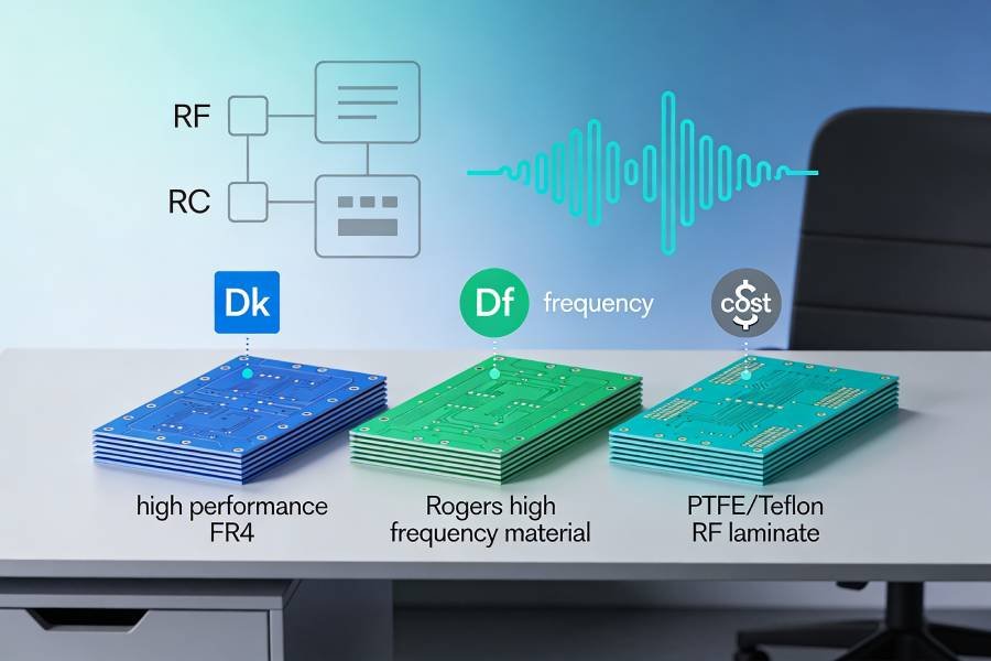
Choosing a laminate for a high‑speed PCB is never just a matter of picking “FR‑4” from a dropdown list. As data rates climb and edges get faster, the dielectric constant (Dk), dissipation factor (Df), glass weave, and even copper roughness of the material start to shape eye diagrams, jitter, and insertion loss just as much as the routing does.
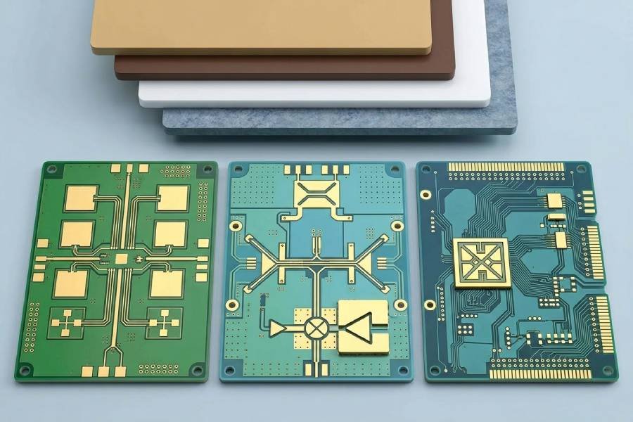
In practice, most high‑speed projects end up considering a short list of material families: standard or enhanced FR‑4 for cost‑sensitive designs, Panasonic Megtron 6 for demanding multi‑gigabit digital links, Rogers 4000 series for mixed high‑speed and RF applications, and PTFE‑based laminates for the most loss‑sensitive microwave and millimeter‑wave systems. Each of these options comes with trade‑offs in performance, manufacturability, availability, and total cost of ownership. This article compares these four material families side by side so that design and sourcing teams can choose a laminate that fits both the signal‑integrity requirements and the manufacturing realities of their next high‑speed PCB.
Why PCB Material Choice Matters for High‑Speed Designs
At low frequencies, PCB material choice mainly affects mechanical strength, thermal behavior, and basic manufacturability. As soon as edge rates become fast enough that traces behave like transmission lines, the laminate’s electrical properties start to directly influence signal integrity. Parameters such as dielectric constant (Dk), dissipation factor (Df), and glass weave structure determine how quickly signals propagate, how much loss they accumulate, and how tightly impedance can be controlled across a stack‑up.
For high‑speed serial links, small changes in Dk and Df can translate into significant differences in insertion loss, eye height, and timing margin over a given trace length. A higher Dk slows signals down and reduces trace width for a given impedance, which can increase attenuation and make manufacturing tolerances more critical. Higher Df increases dielectric loss, which is especially harmful at multi‑gigabit data rates and on long channels such as backplanes or mezzanine interconnects. Copper surface roughness and resin‑to‑glass ratio further shape high‑frequency loss and can impact skew in differential pairs due to glass weave effects.
Beyond pure electrical performance, material choice also affects how easy it is to manufacture and assemble a high‑speed PCB. Some laminates require different lamination profiles, drilling parameters, or surface preparation steps, which can impact yield, lead time, and cost if your fabricator is not familiar with them. Others are designed to be processed with standard FR‑4‑like conditions, making them attractive for designs that push data rates but still need robust and cost‑effective volume production. Understanding where FR‑4, Megtron 6, Rogers 4000, and PTFE‑based materials sit on this spectrum is the key to matching a high‑speed design’s requirements with a realistic manufacturing strategy.
Standard and Enhanced FR‑4
For many high‑speed designs, the starting point is still FR‑4, the workhorse glass‑reinforced epoxy laminate used in the majority of PCBs worldwide. Standard FR‑4 is attractive because it is inexpensive, widely available, and well understood by virtually every PCB fabricator, making it a natural choice for cost‑sensitive products and moderate data rates. However, its relatively higher and less tightly controlled Dk and Df, along with variability between suppliers and batches, limit its usefulness as data rates and channel lengths increase.
Enhanced or “high‑speed” FR‑4 formulations were developed to bridge the gap between generic FR‑4 and more exotic low‑loss laminates. These materials typically offer lower and more consistent Dk and Df, improved glass weave formulations, and better control of high‑frequency loss, while still being compatible with standard FR‑4 processing conditions. Examples include high‑speed or low‑loss FR‑4 families that can support multi‑gigabit serial links over reasonable distances without the cost and process changes associated with PTFE‑based systems. For many digital designs in the low‑ to mid‑single‑digit gigahertz range, enhanced FR‑4 provides a good balance between performance, manufacturability, and total cost.
In practice, standard FR‑4 is often adequate for shorter high‑speed channels, moderate layer counts, and applications where a small amount of additional loss can be absorbed in the system budget. As channels get longer, data rates higher, or compliance margins tighter, moving to an enhanced FR‑4 grade is usually the first step before considering more specialized laminates. At this point, it becomes important to work closely with your PCB manufacturer to confirm which FR‑4 families they stock, what their typical Dk/Df ranges look like at your operating frequency, and how those values are used in stack‑up and impedance calculations.
Panasonic Megtron 6
Panasonic Megtron 6 is a high‑speed, low‑loss laminate family widely used in telecom, networking, and data‑center hardware where multi‑gigabit serial links and long channels are common. Compared with enhanced FR‑4, Megtron 6 offers significantly lower Df and well‑controlled Dk over a broad frequency range, which translates into reduced insertion loss and more predictable delay for high‑speed signals. This makes it attractive for backplanes, line cards, high‑speed mezzanine links, and other applications where eye‑diagram margins are tight and retimers or equalization budgets are limited.
One of the key strengths of Megtron 6 is that it is engineered to be processed with manufacturing conditions similar to FR‑4, avoiding many of the handling challenges associated with PTFE‑based laminates. Fabricators familiar with high‑layer‑count FR‑4 often find it relatively straightforward to qualify Megtron 6 for controlled‑impedance, high‑speed applications, which helps keep yields high and lead times reasonable. At the same time, its lower loss and stable dielectric properties at high frequencies enable designers to extend reach or increase data rates without completely redesigning the stack‑up around exotic RF materials.
From a cost perspective, Megtron 6 sits above enhanced FR‑4 but below many PTFE‑based systems, making it a common “sweet spot” choice when performance demands exceed what FR‑4 can reliably provide. It is particularly well suited to designs using standards like PCI Express, high‑speed Ethernet, and other multi‑gigabit serial protocols that run over tens of centimeters to tens of inches of PCB interconnect. When considering Megtron 6, it is important to confirm material availability, layer count limitations, and any specific stack‑up guidelines with your PCB manufacturer, as not every fab stocks the full Megtron family or supports it across all thicknesses and copper weights.
Rogers 4000 Series
Rogers 4000 series laminates (such as RO4003C and RO4350B) were developed to serve applications that combine high‑speed digital and RF or microwave signals on the same board. Compared with FR‑4, these hydrocarbon‑ceramic materials offer lower and more tightly controlled Dk and Df, which reduces insertion loss and improves impedance stability over frequency. This makes them well suited for designs such as base‑station radios, RF front‑ends, high‑speed SERDES links feeding antennas, and mixed‑signal boards where both digital and RF performance matter.
A major advantage of the Rogers 4000 family is that it is designed to be processed using standard FR‑4 fabrication methods rather than the specialized handling required for many pure PTFE systems. These laminates can typically be drilled, plated, and laminated with conditions similar to FR‑4, which simplifies qualification for PCB manufacturers and helps maintain good yields and predictable costs. At the same time, the more stable dielectric properties of Rogers 4000 materials improve modeling accuracy and make it easier for designers to correlate simulations with measured high‑frequency behavior.
In many high‑speed and RF projects, Rogers 4000 series is used either as the primary laminate or in hybrid stack‑ups where it is combined with FR‑4 or enhanced FR‑4 to balance cost and performance. Critical RF or ultra‑high‑speed layers can be placed on Rogers cores, while less demanding digital and power layers use more economical materials. When taking this approach, it is essential to work closely with your PCB manufacturer on stack‑up design, lamination sequences, and material compatibility to ensure good reliability and consistent impedance across all interfaces.
PTFE‑Based Laminates
PTFE‑based laminates sit at the high end of the performance spectrum for high‑speed and RF PCB materials. Their extremely low Df and very stable Dk over a wide frequency range make them ideal for applications where even small amounts of dielectric loss or phase distortion are unacceptable, such as microwave radios, radar systems, satellite communications, millimeter‑wave links, and precision RF front‑ends. In these regimes, PTFE materials can deliver significantly lower insertion loss and tighter phase control than FR‑4, Megtron‑class, or hydrocarbon‑ceramic laminates.
However, the advantages of PTFE come with notable trade‑offs in manufacturing complexity and cost. PTFE laminates are softer and more chemically inert than epoxy‑based materials, which affects drilling, plating, and adhesion; they often require special surface treatments, specific drill parameters, and tailored lamination profiles to achieve reliable via walls and layer bonds. Fewer PCB manufacturers are deeply experienced with PTFE processing, and yields can suffer if the material is not handled correctly, leading to longer lead times and higher board prices compared with FR‑4, Megtron 6, or Rogers 4000.
Because of this, PTFE‑based systems are typically reserved for the most demanding RF and ultra‑high‑speed use cases, or for portions of a design where their unique properties are truly necessary. In many projects, hybrid stack‑ups are used in which critical RF paths are implemented on PTFE cores while less sensitive digital and power circuitry remains on FR‑4 or other high‑speed laminates to control cost. When considering PTFE, designers should engage the PCB manufacturer early to confirm which PTFE families are supported, what design rules apply, and how the material choice will affect stack‑up, via design, and overall manufacturability.
Side‑by‑Side Material Comparison
The table below summarizes the typical characteristics and use cases of standard/enhanced FR‑4, Megtron 6, Rogers 4000 series, and PTFE‑based laminates for high‑speed PCBs.
Values are indicative ranges rather than exact specifications for any single product.
| Material family | Typical Dk @ high freq | Typical Df @ high freq | Relative loss | Relative cost | Process complexity | Typical use cases |
|---|---|---|---|---|---|---|
| Standard FR‑4 | ~4.2–4.7 | ~0.015–0.02+ | Highest among these options on long high‑speed channels | Lowest | Easiest; widely supported everywhere | General digital PCBs, moderate‑length high‑speed links where some extra loss is acceptable |
| Enhanced / high‑speed FR‑4 | ~3.6–4.1 | ~0.006–0.012 | Lower than standard FR‑4; suitable for many multi‑Gbps links | Low–medium | Similar to FR‑4; easy for most fabs | Cost‑sensitive high‑speed serial designs, shorter backplane/mezzanine links, mainstream networking and computing boards |
| Panasonic Megtron 6 | ~3.3–3.7 (stable vs frequency) | ~0.002–0.005 (very low loss) | Significantly lower dielectric loss than FR‑4; excellent for long multi‑Gbps channels | Medium–high | Generally FR‑4‑like processing; qualified at many high‑end fabs | Data‑center, telecom, networking backplanes, high‑layer‑count high‑speed digital boards (PCIe, high‑speed Ethernet, SERDES) |
| Rogers 4000 series (e.g. RO4003C, RO4350B) | ~3.2–3.6 | ~0.002–0.004 | Very low loss with stable Dk; strong in mixed RF / high‑speed roles | Medium–high | Designed for FR‑4‑like processing, easier than pure PTFE | RF front‑ends, base stations, mixed RF + high‑speed digital, phased‑array and communication systems |
| PTFE‑based laminates | ~2.1–2.6 (very low Dk) | ~0.0005–0.002 (ultra‑low loss) | Lowest dielectric loss; best for very high frequency / long RF paths | Highest | Most demanding: special drilling, plating, and lamination needed | Microwave, millimeter‑wave, radar, satellite and other ultra‑high‑frequency / ultra‑low‑loss applications |
How to Choose the Right Material for Your Project
Selecting a laminate for a high‑speed PCB is ultimately a trade‑off between performance, cost, and manufacturing risk. A practical way to make the decision is to start from your system‑level requirements: target data rates and link lengths, allowable insertion loss budget, operating frequency for any RF paths, and environmental or reliability constraints. If most links are relatively short and operate in the low‑ to mid‑single‑digit gigahertz range with comfortable eye‑diagram margins, enhanced FR‑4 is often sufficient and offers the best cost and availability profile. As soon as channels get longer, margins become tight, or compliance tests start to fail due to loss, it is usually time to consider Megtron‑class or Rogers‑class laminates.
For high‑speed digital backplanes, data‑center interconnects, and networking equipment with long multi‑gigabit links, materials like Megtron 6 frequently hit the right balance: much lower loss than FR‑4 with FR‑4‑like processing and moderate cost. Where RF and microwave performance are equally important, Rogers 4000 series or hybrid stack‑ups that combine Rogers with FR‑4 can deliver stable Dk/Df and good modeling accuracy without the full complexity of PTFE. PTFE‑based laminates should generally be reserved for designs that truly need their ultra‑low loss and very low Dk at microwave or millimeter‑wave frequencies, because they bring higher board cost and more demanding fabrication requirements.
No matter which material family you are considering, the final decision should be made together with your PCB manufacturer. Ask which specific laminates they stock or can source reliably, what Dk/Df values they use in their impedance calculations at your operating frequency, and whether they have established process windows for Megtron‑class, Rogers‑class, or PTFE‑based materials. Involving the fabricator early allows you to choose a laminate that not only meets your signal‑integrity goals, but can also be manufactured consistently at the desired volume and cost, reducing the risk of late‑stage surprises and ensuring that your high‑speed PCB performs in hardware the way it does in simulation.
Working With Your PCB Manufacturer on Material Selection
Even after you have compared FR‑4, Megtron 6, Rogers 4000, and PTFE on paper, the final material decision should be validated with your PCB manufacturer. They can provide real‑world input on which specific laminate grades are in regular stock, how those materials behave in their processes, and what lead times and yields you should expect at your target volumes. This is especially important for Megtron‑class, Rogers‑class, and PTFE‑based laminates, where availability and process experience can vary significantly between fabs.
When you engage your manufacturer, share not just a part number but also your performance goals: operating frequencies, channel lengths, loss budget, and any RF or environmental constraints. Ask them to propose a practical stack‑up using materials they know they can process reliably, along with the Dk/Df values they will apply for impedance calculations at your frequencies of interest. By aligning on material selection, stack‑up, and process capability early, you greatly reduce the risk that a theoretically ideal laminate turns into a sourcing or manufacturability problem, and increase the chances that your high‑speed PCB will behave consistently from prototype through volume production.