Table of Contents
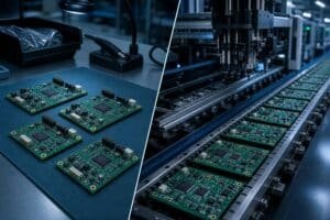
In high frequency PCB design, material selection often determines whether a board will meet its performance targets at real operating frequencies and trace lengths, while still staying within budget and lead time constraints. Many projects that look fine at the schematic or low‑frequency level start to fail only when frequency and interconnect length increase, revealing issues such as excessive loss, impedance drift and temperature‑dependent behavior that can often be traced back to an unsuitable or over‑ambitious choice of PCB laminate.
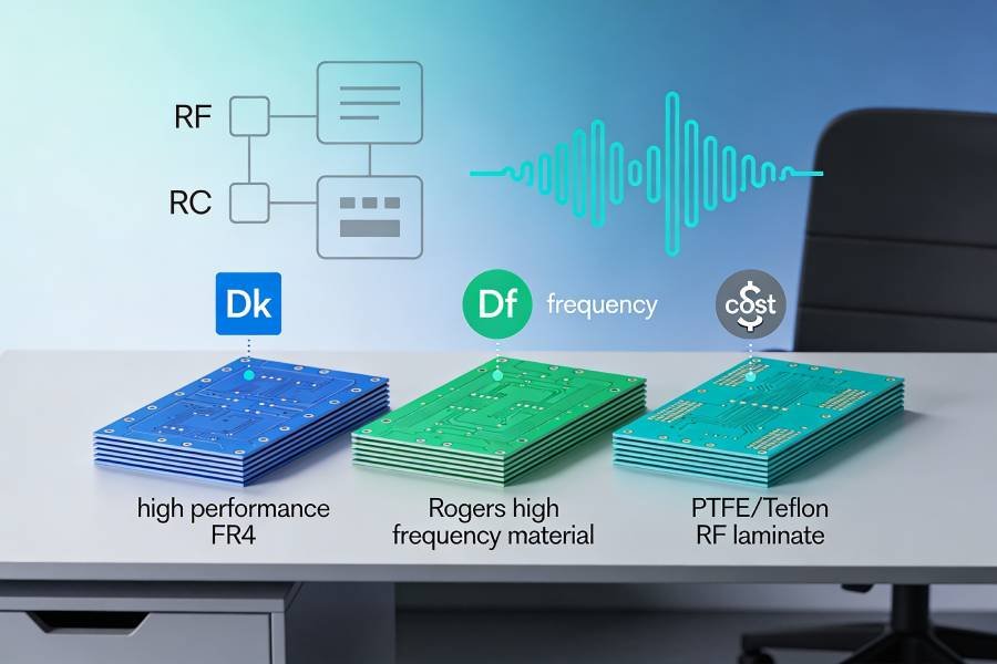
For RF and high‑speed designs, engineers typically balance three main material families: enhanced high‑performance FR4, Rogers‑type hydrocarbon/ceramic laminates and ultra‑low‑loss PTFE/Teflon‑based substrates. These options differ significantly in dielectric constant (Dk), dissipation factor (Df), usable frequency range, thermal stability, processing difficulty and cost, so the right choice should be driven by target frequency, trace length, loss budget and reliability requirements rather than simply picking the most expensive material.
This article first reviews the key electrical and physical parameters that matter for high frequency PCB material selection, then examines when it makes sense to use high‑performance FR4, when to move to Rogers‑class laminates, and when PTFE‑based materials are truly justified. Finally, it presents a practical decision framework to help you choose between these three material families for real projects, and shows how to work with a high frequency PCB manufacturer to translate that decision into a buildable stackup and quotation.
Key Material Parameters for High Frequency PCB Selection
High frequency PCB materials are defined as much by their electrical behavior as by their mechanical and thermal properties. When comparing Rogers, PTFE and high‑performance FR4, the most important parameters to understand are dielectric constant (Dk), dissipation factor (Df), stability over frequency and temperature, copper roughness and basic reliability metrics such as thermal expansion and moisture absorption.
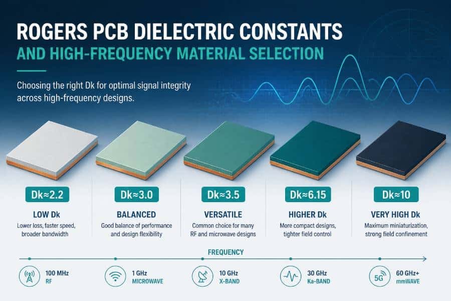
Dielectric Constant (Dk)
The dielectric constant describes how much a material slows down an electromagnetic wave and strongly influences both characteristic impedance and trace width for a given stackup. In high frequency PCBs, lower or moderate Dk materials are often preferred to keep impedance controlled with reasonable geometries and to reduce dispersion, but the most critical requirement is that Dk be well characterized and stable over the intended frequency range. Rogers and PTFE‑based laminates typically provide tighter Dk tolerances and better high frequency models than generic FR4, while high‑performance FR4 improves on standard FR4 but still shows more variation at very high frequencies.
Dissipation Factor (Df) and Insertion Loss
Dissipation factor, or loss tangent, measures how much signal energy is converted to heat as a wave propagates through the dielectric. At RF and microwave frequencies, especially over longer trace lengths or in long backplanes, Df becomes a major contributor to insertion loss and can quickly consume the available link budget if the material is too lossy. High‑performance FR4 offers lower Df than standard FR4 but still more loss than Rogers‑class laminates, while PTFE‑based materials provide the lowest Df and are chosen when ultra‑low loss is required across wide bandwidths or very high frequencies.
Thermal Stability, CTE and Reliability
High frequency designs often see wide temperature excursions, and variations in Dk, Df and board dimensions over temperature can shift impedance, detune filters and alter antenna performance. Coefficient of thermal expansion (CTE) and glass transition temperature (Tg) affect mechanical reliability, especially around vias and solder joints, and mismatched CTE between copper and dielectric can lead to cracking or reliability issues under thermal cycling. Rogers and PTFE materials are engineered for better dielectric and dimensional stability at high frequencies, while high‑performance FR4 provides a reasonable compromise for less extreme conditions and mixed‑signal designs that still need good thermal behavior.
Copper Roughness and Process Considerations
At higher frequencies, current tends to flow near the surface of the conductor (skin effect), which makes copper surface roughness an important factor in conductor loss. Rougher copper increases effective path length and resistance, adding to insertion loss on top of dielectric losses, so many high frequency PCB materials are paired with smoother, low‑profile copper foils to keep loss under control. At the same time, some laminates are more challenging to process—PTFE in particular requires specialized drilling, lamination and surface preparation—so understanding how material properties interact with fabrication processes is essential when deciding between FR4, Rogers and PTFE for a given design.
High Performance FR4: When Is It Good Enough?
High performance or low‑loss FR4 materials are enhanced versions of standard FR4 that offer lower Df, better controlled Dk and improved thermal properties, while remaining compatible with mainstream PCB fabrication processes. They are not true RF laminates, but in many “high frequency” projects they can still provide acceptable performance for certain portions of the design at a much lower cost than Rogers or PTFE.
What High Performance FR4 Actually Means
Compared to standard FR4, high performance FR4 grades typically specify tighter Dk tolerances, lower Df values and higher Tg to improve both signal integrity and thermal reliability. While exact numbers vary by manufacturer, these materials often sit in an intermediate space: significantly better than commodity FR4 at high frequencies, but still more lossy and less stable than dedicated RF laminates.
Frequency and Trace Length Limits for FR4
In practice, high performance FR4 is often sufficient for applications below a few gigahertz, especially when RF or high‑speed traces are relatively short and link budgets are not extremely tight. For example, short RF feed lines, local oscillators, low‑range wireless links or moderate‑speed serial interfaces can frequently run on high performance FR4 without excessive loss, provided that impedance is controlled and routing is careful. As operating frequency, trace length or required dynamic range increase, however, dielectric loss and dispersion in FR4 become more problematic, and this is typically the point where designers start to consider Rogers‑class materials.
Typical Applications in “High Frequency” Designs
In many real‑world high frequency systems, high performance FR4 is used alongside RF laminates, handling digital logic, high‑speed interfaces, control circuitry and power distribution while the most critical RF paths use lower‑loss materials. It is also common in designs where the main concern is high‑speed digital integrity rather than extreme RF performance, such as multi‑gigabit backplanes, networking equipment or mixed‑signal boards with moderate RF content.
Pros and Cons Summary
The main advantages of high performance FR4 are its relatively low cost, wide availability and excellent compatibility with standard PCB manufacturing processes, which often translates into shorter lead times and higher yields. Its disadvantages are higher dielectric loss and less stable high frequency behavior compared to dedicated RF materials, which limit its suitability for long RF paths, very high frequencies or very low‑loss applications. As a result, high performance FR4 is “good enough” when your high frequency requirements are moderate, but for more demanding RF signal chains you will typically need to move up to Rogers‑class or PTFE‑based laminates.
Rogers Hydrocarbon/Ceramic Materials: The Workhorse for Many RF Designs
Rogers hydrocarbon/ceramic laminates, especially the RO4000 series, have become a de‑facto standard for many high frequency PCB designs because they combine good RF performance with FR4‑like manufacturability. They fill the gap between high performance FR4 and PTFE by offering lower loss, tighter Dk control and better high frequency data, without requiring the full set of special processes that pure PTFE materials demand.
Overview of Rogers RO4000 Series (RO4350B, RO4003C, etc.)
The RO4000 family includes widely used grades such as RO4003C and RO4350B, which feature dielectric constants in the range of roughly 3.3–3.5 and low dissipation factors suitable for RF and microwave applications. These laminates are formulated to behave more like RF materials electrically while still being processed with standard epoxy/FR4 fabrication techniques, including conventional drilling, plating and lamination. Compared to generic FR4, they provide more stable Dk and Df over frequency and temperature, which is particularly valuable when designing filters, antennas and impedance‑critical RF lines.
When to Move from FR4 to Rogers
A common rule of thumb is to consider moving from FR4 to Rogers‑class materials when operating frequencies, trace lengths or loss budgets push FR4 close to its limits. For example, if you are designing RF signal paths in the multi‑GHz range with significant trace lengths, or if your system budget allows only modest insertion loss and tight amplitude/phase balance, high performance FR4 may no longer be adequate. Similarly, if you need better control of impedance and phase over temperature or across production lots, the improved dielectric stability and tighter characterization data of Rogers materials become strong arguments for stepping up.
Typical Applications for Rogers Materials
Rogers hydrocarbon/ceramic laminates are widely used in RF front‑end modules, 5G Sub‑6 GHz and some millimeter‑wave boards, power amplifiers, low‑loss feed networks, filters and a variety of antenna structures. They are also common in mixed RF and high‑speed digital systems where the RF sections require lower loss and better dielectric control than FR4 can provide, but where cost or manufacturing considerations make PTFE less attractive. Because they process similarly to FR4, many PCB manufacturers are comfortable fabricating Rogers‑based designs with consistent quality and predictable lead times.
Pros and Cons Summary
The main advantages of Rogers hydrocarbon/ceramic materials are their low dielectric loss, well‑controlled Dk, good high frequency characterization data and compatibility with standard PCB fabrication processes, which together make them a versatile choice for many RF designs. On the downside, they are more expensive than high performance FR4, may have longer lead times or more limited thickness options, and still do not reach the ultra‑low‑loss performance of PTFE‑based laminates at very high frequencies. In practice, Rogers materials are often the “workhorse” solution when FR4 is not good enough for the RF portion of a design but full PTFE performance is not strictly necessary.
PTFE‑Based Laminates: When You Really Need Ultra‑Low Loss
PTFE‑based (Teflon) laminates sit at the top end of high frequency PCB materials, offering the lowest dielectric loss and very stable dielectric properties for demanding RF and microwave applications. They are commonly used when operating frequencies, bandwidths or link budgets are so aggressive that even Rogers‑class hydrocarbon/ceramic materials no longer provide enough margin.
PTFE/Teflon High Frequency Materials Overview
PTFE‑based laminates typically exhibit very low Df and well‑controlled Dk, with values that remain stable over wide frequency and temperature ranges. Many well‑known microwave and millimeter‑wave materials, including certain Duroid and Rogers RO3000 series products, belong to this family and are specifically engineered for high‑end RF filters, couplers, antennas and long transmission lines. Their electrical behavior is ideal for applications where every fraction of a decibel of loss matters, or where phase stability and dispersion must be tightly controlled.
When to Choose PTFE Instead of Rogers
Designers usually step up from Rogers‑class materials to PTFE when operating at very high frequencies (often tens of gigahertz), dealing with long RF paths or ultra‑wideband signals, or when system performance targets leave almost no room for dielectric losses. Examples include automotive radar around 77 GHz, satellite communication links, certain 5G millimeter‑wave front‑ends and precision instrumentation where amplitude and phase accuracy must be maintained over long distances or complex networks. In these regimes, the incremental performance gain over Rogers can justify the higher material and processing costs of PTFE.
Manufacturing Challenges and Cost Impact
The superior electrical performance of PTFE comes with manufacturing trade‑offs: PTFE laminates are mechanically softer, have different CTE characteristics and show poor adhesion to copper without special treatments, which makes drilling, lamination and plating more complex than with FR4 or Rogers hydrocarbon/ceramic materials. Fabricating PTFE‑based boards often requires optimized drilling parameters, dedicated desmear processes, specialized bonding films and careful control of lamination cycles to achieve reliable vias and interlayer adhesion. These extra steps, combined with higher laminate prices and sometimes limited availability or thickness options, typically make PTFE solutions significantly more expensive than FR4 or Rogers‑based designs.
Pros and Cons Summary
PTFE‑based laminates offer the lowest dielectric loss, highly stable Dk and excellent high frequency performance, making them the material of choice for the most demanding RF, microwave and millimeter‑wave circuits. However, they are more expensive, more difficult to process and may have longer lead times or more constrained thickness ranges than Rogers or high‑performance FR4, which limits their use to applications where their performance advantages are truly needed. In many practical designs, engineers reserve PTFE for only the most critical RF sections while using Rogers or FR4 for the rest of the board in a hybrid stackup.
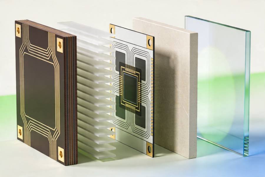
Hybrid High Frequency PCB Stackups (Rogers + FR4)
Hybrid high frequency PCB stackups combine RF laminates such as Rogers or PTFE with high‑performance FR4 in a single board, allowing designers to place low‑loss RF structures only where they are truly needed while keeping the rest of the board on more economical materials. This approach has become very common in mixed RF/digital systems because it offers a practical balance between performance, cost and manufacturability.
Why Hybrid Stackups Are So Common
In many designs, only a relatively small portion of the board—the RF front‑end, filters, antennas or a few critical high‑speed links—truly requires low‑loss, tightly controlled RF materials. Using expensive Rogers or PTFE laminates for the entire PCB would significantly increase cost without proportional performance gains in digital, control or power areas that are far less sensitive to dielectric loss. Hybrid stackups solve this by dedicating one or more RF layers to Rogers or PTFE and building the remaining layers from high‑performance FR4, often with a shared ground plane tying the different material regions together.
Typical Hybrid Stackup Patterns
A common hybrid architecture is to route RF signals on an outer or inner layer made from Rogers material, referenced to an adjacent ground plane, while placing digital logic, power distribution and less critical signals on FR4‑based layers elsewhere in the stack. For example, a stackup might use Rogers for the top signal layer and its adjacent core to implement antennas or RF feed networks, with the rest of the board built from FR4 for processors, interfaces and control circuits. Other designs use Rogers or PTFE only in localized regions or sub‑laminates that are bonded to FR4 sections, creating a composite structure tailored to the RF and digital needs of the system.
Key Design and Manufacturing Considerations
Hybrid stackups introduce additional design and manufacturing challenges, including managing differences in coefficient of thermal expansion, lamination behavior and drilling characteristics between RF materials and FR4. Careful stackup planning is needed to ensure that bonded interfaces remain reliable under thermal cycling and that vias passing through multiple material types maintain good plating, adhesion and dimensional accuracy. Close coordination with a PCB manufacturer experienced in hybrid high frequency constructions is essential to define feasible material combinations, lamination sequences and design rules.
When Hybrid Is Better Than All‑Rogers or All‑PTFE
Hybrid stackups are often the best choice when a design has demanding RF performance requirements in certain sections but also includes substantial digital logic, control and power circuitry, and must meet tight cost targets. By confining Rogers or PTFE to the RF layers and using FR4 elsewhere, designers can achieve near‑RF‑grade performance where it matters while avoiding the expense and fabrication complexity of building the entire board from exotic materials. This makes hybrid high frequency PCBs an attractive default option for many communication systems, 5G infrastructure, radar front‑ends and mixed RF/digital products.
Practical Selection Framework: FR4 vs Rogers vs PTFE
Step 1: Rough partition by frequency and loss
Use frequency and approximate loss budget as your first coarse filter.
- Low to mid RF (typically below about 1–2 GHz), short traces, relaxed loss: standard or high‑Tg FR4 is usually acceptable and gives the best cost and manufacturability.
- Mid to high RF (roughly 2–10 GHz), or multi‑GHz with longer runs / tighter loss budget: consider hydrocarbon/ceramic Rogers materials (e.g., RO4000 family) as a cost–performance compromise.
- Very high frequency (often above 20 GHz, mmWave, 77 GHz radar, etc.) or ultra‑tight link budgets: PTFE‑based laminates (sometimes ceramic‑filled) are typically required for the RF paths.
In practice, “frequency × trace length” is what matters: a 6 GHz path that is only a few millimeters long may survive on high‑performance FR4, while a long feed network at the same frequency may already justify Rogers.
Step 2: Classify by function and signal type
Next, classify the board logically by function before you decide materials.
- Digital / control / low‑speed sections: MCUs, FPGAs, power management, slow interfaces, etc. These almost always go on FR4 (standard or high‑Tg) to keep cost and fabrication simple.
- RF front‑end sections: power amplifiers, LNAs, filters, couplers, LO distribution, phased‑array feed networks. These are the primary candidates for Rogers or PTFE, selected based on Step 1.
- Antennas and critical feed lines: for higher bands or efficiency‑sensitive antennas, designers usually avoid FR4 and move to Rogers or PTFE for the antenna region.
Once you do this partition, you often naturally end up with a hybrid strategy: RF and antenna layers on Rogers/PTFE, everything else on FR4 in the same stackup.
Step 3: Constrain by cost and manufacturability
Now convert “what could work” into “what we will actually build” by adding cost and process constraints.
- Cost‑sensitive, high‑volume products:
- Use FR4 wherever possible.
- Introduce Rogers only on truly critical RF layers, and avoid PTFE unless absolutely required.
- Performance‑driven, moderate‑volume designs:
- For 5–10 GHz systems, consider all‑Rogers or Rogers+FR4 hybrid stackups.
- For mmWave or ultra‑low‑loss links, use PTFE for key RF structures and keep the rest on FR4 or Rogers.
- Fabrication capability and lead time:
- FR4: widely available, cheapest, shortest lead time.
- Rogers hydrocarbon/ceramic: requires some care but is largely FR4‑compatible; most high‑frequency PCB shops can support it with standard processes.
- PTFE: soft, different CTE, and poor copper adhesion unless treated; it needs specialized drilling, plating, and lamination controls and often carries higher cost and longer lead time.
A pragmatic workflow is to start from an “ideal” materials plan based purely on RF performance, then iterate with your PCB fabricator to see whether a cheaper or more manufacturable Rogers or hybrid option can still meet the specs.
Step 4: Use a simple decision table
| Question | If answer is “Yes” → Likely direction |
|---|---|
| Max frequency < ~1–2 GHz and traces are short | Stay on FR4; focus on impedance control and stackup basics. |
| Operating in 2–10 GHz or loss is getting tight | Move RF sections to Rogers (RO4000‑class); consider hybrid. |
| Above ~20 GHz / mmWave or ultra‑low loss needed | Use PTFE (or advanced RF laminates) for critical RF paths. |
| RF area is a small fraction of total board | Hybrid stackup: RF layers on Rogers/PTFE, rest on FR4. |
| Product is extremely cost/volume sensitive | Minimize RF materials; use FR4, with targeted Rogers “islands”. |
| Fabricator has no PTFE experience | Prefer Rogers or Rogers+FR4 hybrid instead of full PTFE. |
Concrete examples:
- A 5G sub‑6 GHz small cell often routes RF and antenna structures on Rogers with inner digital and power layers on FR4 in a hybrid stackup.
- A 77 GHz automotive radar front‑end typically uses PTFE or comparable ultra‑low‑loss material for the antenna and front‑end lines, backed by FR4 or Rogers for control, processing, and power.
tep 5: Lock the choice into stackup and simulation
Once materials are chosen, you still need to close the loop through stackup design and pre‑layout simulation.
- Stackup definition: place RF signal layers adjacent to solid reference planes; group RF materials together to reduce CTE‑mismatch stress; confirm actual laminate part numbers, Dk/Df, and thickness tolerances with the fabricator.
- Pre‑layout and post‑layout simulation: use manufacturer Dk/Df vs. frequency data for transmission‑line, impedance, and S‑parameter simulations; in hybrids, pay special attention to vias that cross multiple material interfaces.
With these five steps, material selection becomes a traceable engineering decision rather than trial and error, and it gives purchasing and the PCB vendor a clear, defensible baseline to work from.
Conclusion: Match the Material to the Job
Choosing between FR4, Rogers, PTFE, or a hybrid stackup is ultimately about matching material capabilities to what your RF design actually needs. FR4 remains the workhorse for digital, control, and lower‑frequency sections thanks to its low cost, wide availability, and easy fabrication. Rogers hydrocarbon/ceramic laminates step in when you need lower loss, tighter Dk control, and better high‑frequency behavior, but still want FR4‑like processing and reasonable cost. PTFE‑based materials push performance even further, enabling ultra‑low loss and excellent stability at microwave and mmWave frequencies, at the cost of more demanding processing and higher price.
For many real‑world products, the most effective strategy is not “all FR4” or “all exotic,” but a hybrid stackup where RF layers run on Rogers or PTFE while inner layers stay on FR4 for digital logic, power, and mechanical strength. A simple, repeatable selection workflow—starting from operating frequency and loss budget, then factoring in function partitioning, cost targets, and your fabricator’s capabilities—turns material choice from guesswork into an engineering decision. If you make that process explicit in your design flow and review checklists, you’ll get more predictable RF performance, smoother interaction with PCB vendors, and fewer surprises when the first boards land on the bench.