Table of Contents
High‑frequency PCB designers rarely choose a Rogers material just by brand name alone—what really drives the decision is the dielectric constant (Dk) and loss behavior of each laminate across the target frequency band. Rogers offers a wide range of high‑frequency PCB materials with dielectric constants roughly spanning from about 2.2 up to around 11, which allows RF, microwave and high‑speed digital engineers to match substrate properties to antenna size, line impedance, insertion loss and overall system performance.
This article provides a practical overview of dielectric constant for Rogers PCB materials: what Dk means in real designs, typical dielectric constant ranges for popular Rogers laminates such as the RO4000 and RO3000 series, how Dk and Df together affect RF and high‑speed behavior, and how to choose a suitable material for 5G, radar, satellite and other high‑frequency applications. It is written for engineers and buyers who want to understand not only “what the numbers are”, but also how to translate those dielectric constants into better PCB stackups, cleaner signal integrity and more reliable products in different markets and operating environments.
Why dielectric constant matters so much in high‑frequency PCB materials
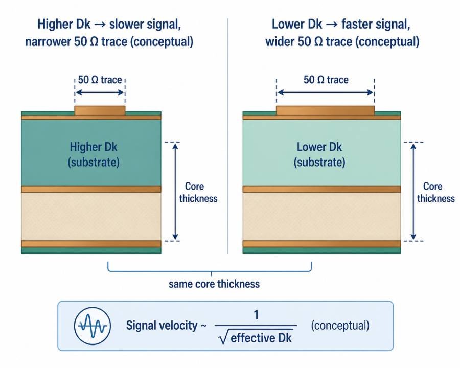
In high‑frequency PCB design, dielectric constant (Dk) is usually the first number RF and high‑speed engineers look at when comparing materials, because it directly affects signal speed, impedance and signal integrity. A higher dielectric constant slows signals down and concentrates the electric field closer to the substrate, while a lower Dk lets signals travel faster and generally makes it easier to control impedance and reduce certain types of crosstalk.
As frequency increases into the multi‑gigahertz range, the impact of dielectric properties becomes much more pronounced: conductor loss is no longer the only concern, and dielectric loss tied to Dk and loss tangent (Df) can become a major contributor to total insertion loss. At these frequencies, any variation in Dk over frequency, temperature or between material batches can shift trace impedance, delay and phase enough to degrade eye diagrams, break timing margins or distort RF matching networks.
This is exactly where Rogers high‑frequency laminates stand out: compared with general‑purpose FR‑4, they are engineered for a much more stable and well‑controlled dielectric constant over the relevant RF and microwave bands. That stable Dk allows designers to hit tight impedance targets, keep signal attenuation predictable and maintain consistent performance across different production batches and operating environments, which is critical for 5G, radar, satellite and other high‑frequency systems deployed worldwide.
Overview of Rogers high‑frequency material families and dielectric constant ranges
Main Rogers high‑frequency laminate families
Rogers offers several major families of high‑frequency PCB laminates, each with its own dielectric constant range, loss level and processing characteristics. For most RF and microwave designers, the RO4000 and RO3000 series are the most common starting points, with additional ceramic and specialty materials used for very high Dk or special mechanical requirements.
At a high level, the RO4000 series (including laminates such as RO4003C and RO4350B) are glass‑reinforced hydrocarbon/ceramic materials designed to combine good RF performance with FR‑4‑like processing and cost. The RO3000 series, by contrast, are ceramic‑filled PTFE composites that push loss and dielectric stability even further, targeting demanding applications up to tens of gigahertz, including 77 GHz radar and other mmWave systems.
Typical dielectric constant ranges by family
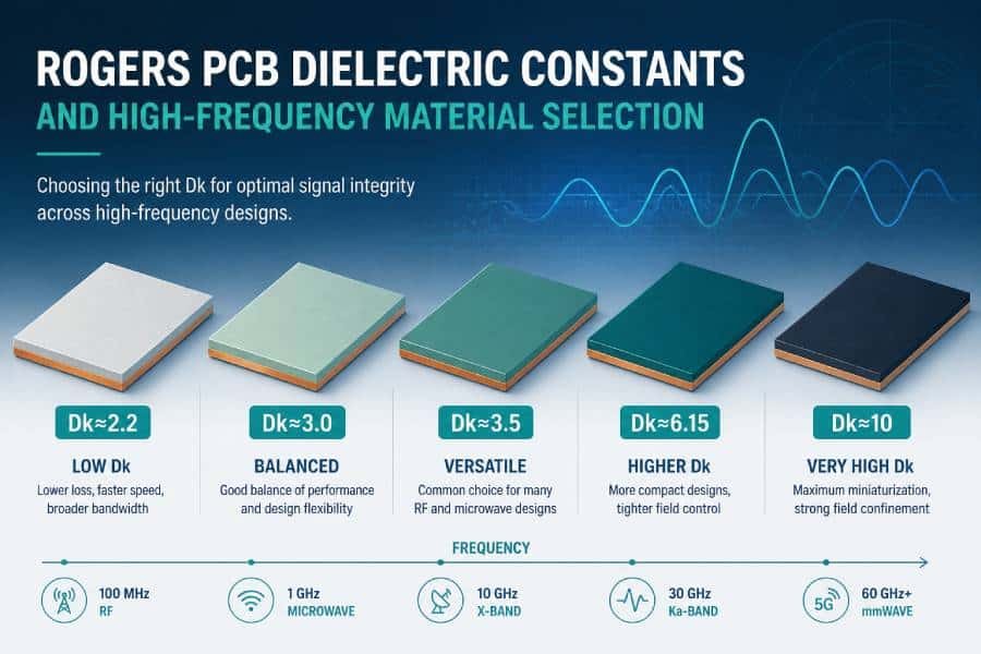
From a dielectric constant point of view, Rogers high‑frequency materials cover a broad range, which allows designers to match substrate Dk to antenna size, line impedance and package constraints. The following conceptual ranges give a useful “mental map” for the most common families:
- RO4000 series: roughly from about 2.5 up to around 6 in dielectric constant, depending on the specific laminate, with popular types like RO4003C and RO4350B sitting in the Dk ≈ 3.3–3.5 range for RF and microwave use.
- RO3000 series: typically in the Dk range of about 3 to 10, with materials such as RO3003 around Dk ≈ 3.0 and others like RO3010 or RO3035 offering higher Dk for more compact structures and special filter or antenna designs.
- Higher‑Dk ceramic laminates: selected ceramic‑based materials can reach Dk values around 6 or higher, supporting very compact resonators or antennas in space‑constrained RF modules, albeit with different processing requirements.
These ranges show why Rogers laminates are popular in high‑frequency design: instead of being locked into a single Dk like standard FR‑4, engineers can choose from a spectrum of dielectric constants to optimize miniaturization, impedance, loss and cost for each project.
Key dielectric concepts: Dk, Df, frequency dependence and TCDk
Dielectric constant (Dk): how it affects signal speed and impedance
In PCB materials, the dielectric constant (Dk, sometimes written as εr) describes how strongly the substrate interacts with an electric field and how much electrical energy it can store compared to a vacuum. For high‑frequency and high‑speed designs, this directly translates into signal speed and impedance: a higher Dk slows signals down and increases capacitance, while a lower Dk lets signals travel faster and generally reduces capacitance for a given geometry.
Practically, signal velocity in a PCB trace scales roughly with the inverse square root of the effective dielectric constant, so changing from a material with Dk around 4.5 to one with Dk around 3.0 can noticeably reduce propagation delay and change the trace width required for a given impedance. This is why Rogers PCB materials, which often have relatively low and stable Dk values, are widely used when designers need consistent impedance and predictable timing across a wide frequency range.
Dissipation factor (Df): how it relates to loss and eye quality
Dissipation factor (Df, or loss tangent) describes how much of the electromagnetic energy traveling through a dielectric is converted into heat rather than being transmitted. In simple terms, Dk governs signal speed and impedance, while Df sets how much insertion loss and eye‑diagram degradation you will see due to dielectric loss as frequency increases.
Low‑Df materials such as many Rogers laminates can significantly reduce dielectric loss in RF transmission lines and high‑speed serial links compared with standard FR‑4, especially above a few gigahertz. This helps maintain higher signal‑to‑noise ratio, cleaner eye openings and more robust link budgets in long backplane traces, antenna feeds, filters and other critical high‑frequency structures.
Frequency dependence and temperature coefficient of Dk (TCDk)
Despite the name “dielectric constant”, Dk is not truly constant—it changes with frequency, temperature, material thickness and even the way it is measured. Many common PCB materials show a noticeable shift in Dk between 1 GHz and 10 GHz, and some FR‑4 formulations also vary significantly with temperature, which can lead to impedance and phase drift over operating conditions.
To address this, Rogers high‑frequency materials are designed with a relatively flat Dk over the intended RF band and a low temperature coefficient of dielectric constant (TCDk), meaning their Dk changes only slightly as temperature varies. For high‑frequency systems deployed in different climates and thermal environments, such as outdoor 5G base stations or automotive radar modules, this stability in Dk over frequency and temperature is one of the main reasons designers choose Rogers laminates over generic FR‑4.
Dielectric constant comparison of representative Rogers materials (with RO4350B focus)
Typical Dk and Df values for popular Rogers laminates
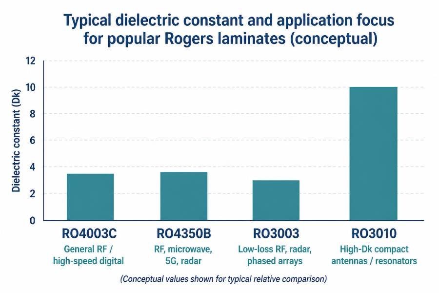
The table below summarizes typical dielectric constant and loss behavior for several widely used Rogers high‑frequency laminates. Values are indicative, based on commonly cited RF conditions around 10 GHz and room temperature, and should be treated as conceptual design guidance rather than specification limits.
| Material | Family | Typical Dk (RF / microwave) | Typical Df (loss tangent, RF) | Dk stability (freq / temp) | Typical use cases |
|---|---|---|---|---|---|
| RO4003C | RO4000 | ≈ 3.4–3.6 | ≈ 0.002–0.003 | Very good | General RF, microwave, high‑speed digital |
| RO4350B | RO4000 | ≈ 3.4–3.5 | ≈ 0.003–0.004 | Very good | RF, microwave, mmWave, 5G, radar, mixed‑signal |
| RO3003 | RO3000 | ≈ 3.0 | ≈ 0.001–0.0015 | Excellent | Low‑loss RF, radar (24/77 GHz), precision filters |
| RO3010 | RO3000 | ≈ 10 | ≈ 0.002–0.003 | Excellent | High‑Dk compact antennas, resonators, special filters |
From this comparison, RO4003C and RO4350B sit in a similar mid‑Dk range around 3.4–3.6, making them popular “workhorse” materials for RF and high‑speed designs that need controlled impedance and moderate loss without extreme miniaturization. RO3003 pushes loss lower again while keeping Dk around 3.0, which is attractive for long RF runs and very low‑loss phased‑array or radar applications, whereas RO3010 represents the high‑Dk end of the spectrum, enabling much more compact resonant structures and antennas.
Quick recap: RO4350B dielectric constant in the Rogers lineup
Within this group, RO4350B stands out as a laminate that combines a mid‑range dielectric constant around 3.48 at RF frequencies with relatively low loss and FR‑4‑like processing. Its Dk is high enough to keep antenna and filter geometries reasonably compact, yet low enough to support comfortable impedance control and manageable propagation delay for mixed RF and high‑speed digital designs.
If you want a deep dive into RO4350B specifically—covering its dielectric constant, design Dk vs process Dk, impact on impedance, loss and phase, and practical design tips—you can refer to the dedicated article “RO4350B dielectric constant explained: parameters, design impact and applications,” which focuses entirely on that laminate. That detailed view complements the broader comparison here and helps you decide when RO4350B is the right Rogers material within a given Dk range.
How to choose the right Rogers dielectric constant for your frequency band and application
Matching dielectric constant to frequency range
The higher your operating frequency, the more critical it becomes to choose a laminate with a stable and appropriately low dielectric constant and loss tangent. For sub‑6 GHz RF and many “moderate‑speed” digital designs, mid‑Dk Rogers materials in the range of roughly 3.3–3.6, such as RO4003C or RO4350B, usually offer a good balance between impedance control, loss and cost.
As you move into higher bands like 24 GHz and 28 GHz 5G, 24 GHz or 77 GHz automotive radar and other mmWave systems, materials with very low loss and tightly controlled Dk—such as RO3003 or other RO3000 series laminates—become more attractive, especially for long RF paths or phased‑array feed networks. In these regimes, both Dk stability and very low Df help maintain a predictable loss budget and phase behavior across the entire operating band.
Recommended Dk ranges for typical applications
A useful way to think about Rogers dielectric constants is by grouping them into approximate ranges that suit different types of applications:
- Sub‑6 GHz wireless and general RF modules:
For cellular, Wi‑Fi, GNSS and other RF systems below roughly 6 GHz, mid‑Dk laminates around 3.3–3.6 (for example RO4003C or RO4350B) typically provide sufficient performance while remaining economical and easy to process. - 24 GHz radar, 26–28 GHz 5G and similar mmWave links:
For these higher bands, lower‑loss materials in the Dk ≈ 3.0–3.5 range with very low Df—such as RO3003 or carefully chosen RO4000 series laminates—help keep insertion loss and phase error under control, especially in long feed networks and phased‑array structures. - Compact antennas, resonators and filters with strict size constraints:
When miniaturization is the top priority, higher‑Dk Rogers materials (for example laminates with Dk around 6 or even close to 10, such as RO3010) allow shorter electrical lengths and smaller resonant elements at the same frequency, at the cost of more demanding design and potentially higher sensitivity to manufacturing tolerances.
Balancing performance, manufacturability and cost
Beyond pure Dk and Df numbers, material selection is always a trade‑off among performance, manufacturability and cost. Mid‑Dk materials such as RO4003C and RO4350B are often the most cost‑effective choice for high‑frequency boards that must be manufactured at scale using FR‑4‑like processes in global PCB production hubs. Ultra‑low‑loss, lower‑Dk laminates like RO3003 or high‑Dk ceramics should be reserved for the parts of the design where their benefits clearly justify the added material and processing cost.
In practice, many engineers adopt hybrid stackups that place Rogers materials with carefully chosen dielectric constants only on the critical RF or high‑speed layers, while using FR‑4 or other cost‑effective substrates for power and low‑speed logic layers. This approach lets them optimize dielectric properties where they matter most, without sacrificing manufacturability or budget for the entire PCB.
Practical details about Dk that are easy to overlook
Thickness, batch variation and “real” Dk on your board
Even though Rogers PCB materials are specified with tight dielectric constant tolerances, Dk is not exactly the same across all thicknesses and production batches of the same laminate. Thinner cores can show slightly different effective Dk than thicker ones, and small lot‑to‑lot variations within the allowed tolerance band can still cause measurable changes in impedance and phase delay on critical RF or high‑speed traces.
For hybrid Rogers + FR‑4 stackups, the situation is even more sensitive: if the Dk difference between layers is too large or poorly controlled, via transitions and layer changes can introduce impedance steps and unwanted resonances. To keep designs robust, it is important to confirm the exact material type, thickness, copper weight and target Dk with your PCB manufacturer during stackup planning, and to use impedance coupons on early builds to validate the effective Dk on the actual production line.
Copper roughness and effective dielectric constant
At high frequencies, the roughness of the copper conductor surface can significantly increase both conductor loss and the effective dielectric constant seen by a propagating wave. Rough copper effectively lengthens the path that current must follow along the surface, which increases resistance and can cause Dk extracted from circuit measurements to appear higher than the intrinsic material value reported in datasheets.
For modern high‑speed and mmWave designs, using low‑profile or very low‑profile copper foils on Rogers laminates is often recommended to minimize the impact of surface roughness on loss and effective Dk. Designers should obtain copper roughness data from the laminate supplier or PCB manufacturer, and, when possible, include roughness effects in field‑solver models to avoid underestimating insertion loss and misinterpreting measured dielectric properties.
Process interactions and design Dk calibration
PCB fabrication processes such as lamination pressure, resin flow, plating thickness and surface treatments can all influence the geometry and electromagnetic environment of traces, which in turn affects the effective dielectric constant experienced by signals. In high‑precision RF or high‑speed designs, neglecting these process‑induced variations can lead to a gap between simulated and measured impedance, delay or S‑parameters, even when the base laminate Dk is well controlled.
A practical way to manage this is to treat design Dk as a calibrated value rather than a fixed number from a table: start with the laminate supplier’s recommended design Dk, then refine it using measurements from simple test structures on your prototypes. Over time, building an internal library of “effective Dk” values for different Rogers materials, thicknesses, copper types and manufacturing partners will make your impedance and loss predictions more accurate for future projects.
A simple step‑by‑step flow for selecting Rogers dielectric constants
Step 1 – Define your frequency band and signal type
Start by clearly identifying the highest operating frequency and the type of signals you are dealing with: RF carrier, wideband modulation, narrowband radar pulses, or high‑speed serial data. For example, a 3.5 GHz 5G small cell, a 24 GHz radar module and a 25 Gbps SerDes link will not have the same material requirements, even if they share the same board.
Step 2 – Set targets for impedance, loss and phase stability
Next, estimate how tight your impedance tolerance must be, how much insertion loss your system can tolerate, and how sensitive performance is to phase or delay variation. Applications with long RF feed lines, phased‑array networks or very long high‑speed links will typically require lower Dk variation and much lower Df than short, less critical interconnects. This step will help you decide whether you can stay in a mid‑Dk family like RO4000 or should consider lower‑loss RO3000 materials.
Step 3 – Choose a suitable Dk range and candidate Rogers families
Based on frequency and performance needs, select an approximate dielectric constant range and map it to candidate Rogers families and laminates. For example, Dk ≈ 3.3–3.6 might point you toward RO4003C or RO4350B, while Dk ≈ 3.0 with ultra‑low loss suggests RO3003, and high‑Dk requirements for compact antennas might lead you to laminates like RO3010.
Step 4 – Check manufacturability, availability and cost
Once you have a short list of candidate materials, verify that they are compatible with your PCB manufacturer’s processes (drilling, lamination, plating) and available with reasonable lead times and minimum order quantities. Many volume RF designs favor RO4000 laminates because they can be processed on FR‑4‑like lines in major manufacturing hubs, while some RO3000 or high‑Dk ceramics may require more specialized fabrication and come with higher material cost.
Step 5 – Work with your PCB partner to finalize stackup and design Dk
With candidate materials selected, collaborate with your PCB fabricator to build a realistic stackup that includes dielectric thicknesses, copper weights and expected tolerances. Use the laminate supplier’s recommended design Dk values together with your fabricator’s impedance tools to define target line widths, spacings and reference plane locations for critical RF and high‑speed layers. This is also the right time to decide whether a hybrid Rogers + FR‑4 construction makes sense for your cost and performance goals.
Step 6 – Prototype, measure and refine the effective Dk
Finally, build initial prototypes with impedance test coupons and simple RF structures (such as microstrip lines and resonators) to measure real‑world impedance, loss and phase delay. Use these measurements to refine the effective design Dk and Df used in your simulation and stackup calculations, so future revisions and related products can start from values that already match your fabrication process. Over time, this iterative approach turns Dk from an abstract datasheet number into a well‑understood design parameter tailored to your specific Rogers materials, PCB partner and application space.

Conclusion
You now have a high‑level roadmap for working with Rogers PCB dielectric constants—from understanding Dk and Df, to comparing key laminates, to building a step‑by‑step selection flow for real RF and high‑speed projects. If you need help turning these dielectric constant choices into a manufacturable PCB stackup, or you want to prototype RO4003C, RO4350B or RO3003 boards for your next 5G, radar or high‑speed design, feel free to contact our engineering team for material recommendations, stackup review and volume production support.