Table of Contents
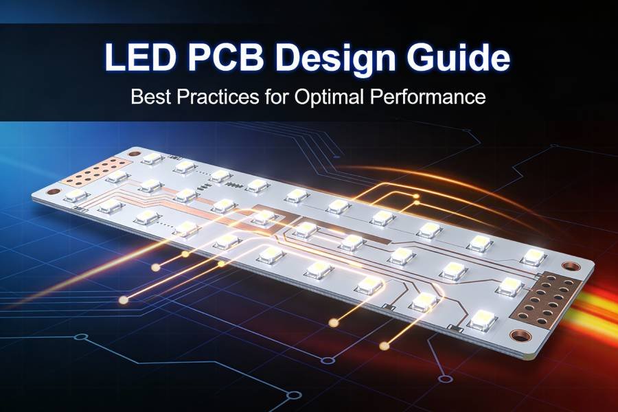
Introduction
Choosing the wrong LED PCB substrate can cost you thousands in redesigns, premature failures, and disappointed customers. Yet, many engineers and product designers underestimate how profoundly the base material affects LED performance, thermal management, and overall system reliability.
The substrate isn’t just a mounting platform—it’s the foundation that determines whether your LEDs will shine brightly for 50,000 hours or fade after a few thousand. It dictates whether your design will handle 15 watts per LED or struggle with just one watt. It influences whether your product will work flawlessly in a desert environment at 60°C or fail catastrophically.
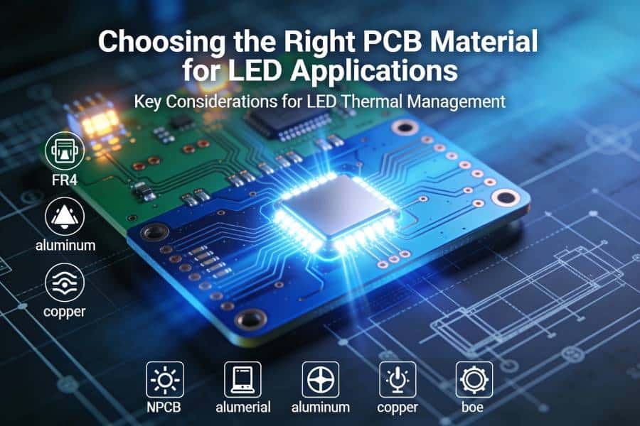
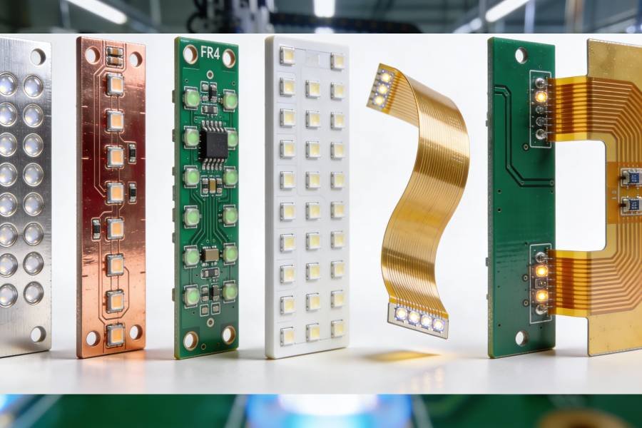
In 2026, LED PCB technology offers six distinct substrate options, each engineered for specific performance requirements and budget constraints. Aluminum LED PCBs have become the industry workhorse, balancing excellent thermal performance with affordability. Copper core PCBs push thermal limits for the most demanding applications. FR4 boards serve low-power needs economically. Ceramic substrates deliver uncompromising reliability in extreme conditions. Flexible PCBs enable innovative form factors, while hybrid designs strategically combine multiple materials for optimized performance.
This comprehensive guide examines all six LED PCB types in detail. You’ll learn the technical specifications, thermal conductivity ratings, cost implications, advantages, disadvantages, and ideal applications for each material. By the end, you’ll have the knowledge to confidently select the optimal LED PCB substrate for your specific project requirements—whether you’re developing automotive lighting, medical devices, consumer electronics, or industrial illumination systems.
Let’s start by understanding what makes LED PCB substrate selection so critical, then dive deep into each material type.
Understanding LED PCB Base Materials
Before comparing specific materials, it’s essential to understand why substrate selection matters so much for LED applications.
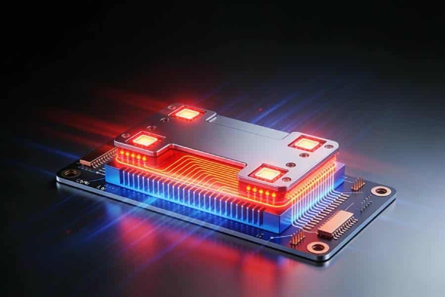
Unlike standard electronics that generate modest heat, LEDs convert a significant portion of input power into thermal energy rather than light. A typical LED might be only 30-40% efficient at converting electricity to photons—the remaining 60-70% becomes heat that must be dissipated through the PCB substrate. This heat, if not properly managed, causes:
- Reduced light output: LEDs dim as temperature rises
- Color shift: LED wavelength changes with temperature
- Accelerated degradation: Every 10°C increase can cut lifespan in half
- Catastrophic failure: Excessive heat can permanently damage LED dies
The PCB substrate serves as the critical thermal pathway, conducting heat away from LED junctions to external heat sinks or ambient air. This is why thermal conductivity—measured in watts per meter-kelvin (W/mK)—is the most important specification when evaluating LED PCB materials.
Key Factors to Consider When Choosing LED PCB Material:
- Thermal Conductivity
The substrate’s ability to conduct heat away from LEDs. Higher values enable better thermal management and support higher-power LEDs. - Cost-Effectiveness
Material and manufacturing costs vary dramatically—from economical FR4 at $1-3 per board to premium aluminum nitride ceramic at $50+ per board. - Power Handling Capacity
Each substrate has practical limits for LED power density. Exceeding these limits causes thermal runaway and premature failure. - Application Requirements
Operating environment (temperature extremes, vibration, chemicals), form factor constraints (rigid vs flexible), and reliability expectations all influence material choice. - Electrical Insulation
While conducting heat efficiently, the substrate must also provide electrical isolation between the circuit and any metal backing. - Mechanical Properties
Dimensional stability, shock/vibration resistance, and machinability affect both manufacturing and long-term reliability.
Understanding these fundamentals helps explain why six different LED PCB types exist—each optimizes different performance parameters for specific use cases. For expert guidance on material selection for your specific application, explore our Technical Capabilities page.
Now, let’s examine each LED PCB type in comprehensive detail, starting with the most popular option.
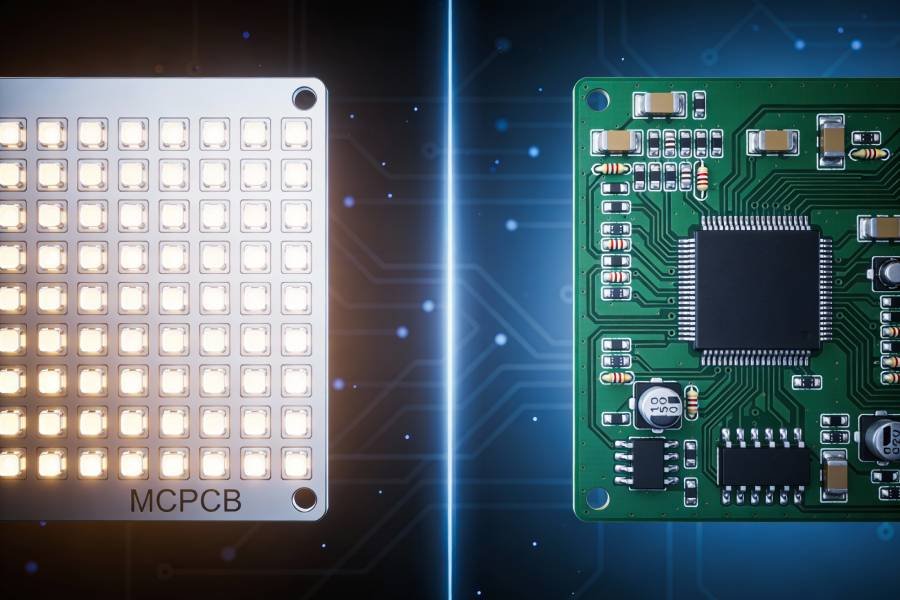
Type 1 - Aluminum LED PCB (MCPCB - Metal Core PCB)
What is Aluminum LED PCB?
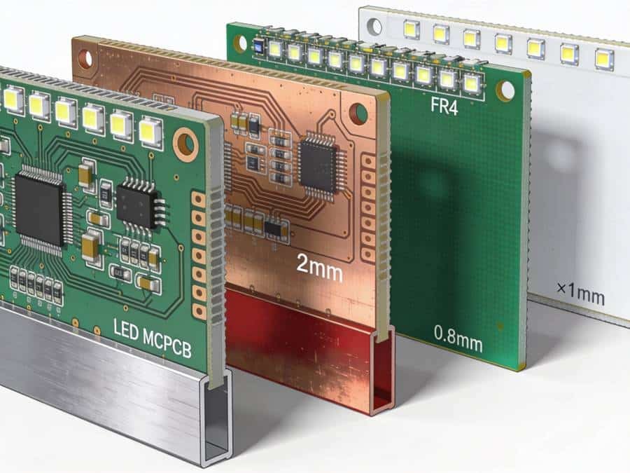
Aluminum LED PCB, commonly known as MCPCB (Metal Core Printed Circuit Board) or aluminum-backed PCB, represents the most widely used substrate for LED applications worldwide. Its dominance stems from delivering excellent thermal performance at an affordable price point—making it the sweet spot for the majority of LED lighting projects.
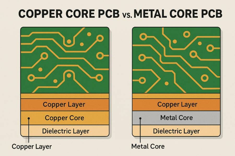
The structure consists of three primary layers:
- Aluminum Base Layer (typically 1.0-3.0mm thick): Provides mechanical support and acts as the primary heat spreader
- Dielectric Layer (50-200μm): A thermally conductive but electrically insulating material that bonds the circuit layer to the aluminum base
- Copper Circuit Layer (usually 1-2oz): Contains the electrical traces and LED mounting pads
The magic happens in the dielectric layer. Unlike traditional FR4 insulation that blocks both electricity AND heat, specialized dielectric materials used in aluminum LED PCBs conduct heat efficiently (1-3 W/mK) while maintaining electrical isolation. This allows heat from mounted LEDs to transfer through the dielectric into the aluminum base, which then spreads it across a larger area for dissipation.
Common aluminum alloys used include:
- 5052: Most popular, good corrosion resistance and machinability
- 6061: Higher strength, commonly available
- 1100: Highest thermal conductivity, softer material
Technical Specifications
| Parameter | Value |
|---|---|
| Thermal Conductivity | 1.0-2.0 W/mK (dielectric layer) |
| Aluminum Base Thermal Conductivity | 120-180 W/mK |
| Typical Board Thickness | 1.0mm, 1.2mm, 1.5mm, 2.0mm, 3.0mm |
| Dielectric Layer Thickness | 50μm, 75μm, 100μm, 150μm, 200μm |
| Copper Layer | 1oz (35μm), 2oz (70μm), 3oz (105μm) |
| Operating Temperature Range | -40°C to +120°C |
| Dielectric Breakdown Voltage | >3000V |
| Thermal Resistance | 0.5-3.0 °C/W (varies with area) |
| Coefficient of Thermal Expansion | 23-26 ppm/°C |
Advantages of Aluminum LED PCB
- Excellent Heat Dissipation
Aluminum LED PCBs offer thermal conductivity 8-10 times superior to standard FR4 boards. This dramatic improvement enables the use of higher-power LEDs while maintaining safe operating temperatures. The aluminum base efficiently spreads heat across the entire board surface, preventing hot spots that cause premature LED failure. - Outstanding Cost-Effectiveness
Among metal core options, aluminum provides the best price-to-performance ratio. Manufacturing costs are 60-70% lower than copper core PCBs while still delivering professional-grade thermal management. For commercial lighting projects where hundreds or thousands of boards are needed, this cost advantage translates to significant savings without compromising performance. - Lightweight Design
Aluminum’s low density (2.7 g/cm³) makes LED assemblies lighter than copper alternatives, simplifying mounting and reducing structural load requirements—particularly important for automotive and aerospace applications where weight optimization matters. - Dimensional Stability
The low coefficient of thermal expansion (CTE) ensures aluminum LED PCBs maintain dimensional accuracy across temperature cycles. This stability prevents thermal stress on solder joints and LED components, enhancing long-term reliability. - Robust Mechanical Strength
Aluminum provides excellent structural rigidity, protecting delicate LED components during handling, shipping, and installation. The boards resist bending and warping better than thin FR4, reducing damage during manufacturing and assembly. - Simplified Heat Sink Integration
The aluminum base can function as an integrated heat sink or easily attach to external heat sinks with minimal thermal interface resistance. Many designs use the PCB itself as the primary cooling solution, eliminating separate heat sink components and reducing overall system costs. - Environmentally Friendly
Aluminum is highly recyclable with established recycling infrastructure worldwide. At end-of-life, aluminum LED PCBs can be recovered and reprocessed with minimal environmental impact—an increasingly important consideration as sustainability regulations tighten globally.
Disadvantages
- Lower Thermal Conductivity Than Copper
While excellent compared to FR4, aluminum’s thermal performance falls short of copper core PCBs. Applications requiring extreme heat dissipation (>5W per LED) may strain aluminum’s capabilities, necessitating larger board areas or external cooling solutions. - Rigid Construction Only
Aluminum LED PCBs cannot flex or conform to curved surfaces. Projects requiring bendable or flexible lighting solutions must use flexible PCB materials instead, limiting aluminum’s versatility in certain applications. - Limited Layer Count
Most aluminum LED PCBs are single-sided or double-sided designs. Complex circuits requiring multilayer construction face challenges, as thermal vias and layer stack-ups become complicated with metal core substrates. - Electrical Isolation Considerations
While the dielectric layer provides electrical insulation, designers must carefully manage high-voltage applications. Defects or damage to the dielectric can create dangerous short circuits between the circuit layer and the grounded aluminum base. - Thermal Via Complications
Creating thermal vias through the aluminum base requires specialized drilling and filling processes, adding cost and complexity compared to standard PCB fabrication.
Best Applications for Aluminum LED PCB
- Street Lighting
High-power LED street lamps benefit enormously from aluminum PCB thermal management. Typical street light LED modules dissipate 50-150 watts, making aluminum’s heat spreading capability essential for achieving 50,000+ hour lifespans in outdoor environments. - Automotive Lighting
Headlights, taillights, daytime running lights, and interior ambient lighting all use aluminum LED PCBs. The combination of thermal performance, vibration resistance, and cost-effectiveness makes aluminum ideal for automotive requirements, where reliability is critical but volume production demands reasonable costs. - Commercial Lighting
Office LED panels, retail spotlights, warehouse high-bay fixtures, and commercial downlights represent huge markets for aluminum LED PCBs. These applications typically use medium-power LEDs (1-3W each) in multi-LED arrays—perfectly suited to aluminum’s thermal capabilities. - LED Displays and Signage
Indoor and outdoor LED video displays, digital billboards, and illuminated signage use aluminum PCBs to manage heat from densely packed LED arrays. The rigid mechanical structure also provides mounting stability for large display panels. - Backlighting Applications
Television backlights, computer monitor backlights, and large signage backlights benefit from aluminum’s ability to spread heat evenly across large panel areas, ensuring uniform brightness and color temperature. - General Illumination Products
LED bulbs, downlights, track lighting, spotlights, and panel lights for residential and commercial use predominantly employ aluminum LED PCBs, balancing performance with manufacturing costs to hit consumer price points.
Aluminum LED PCB Cost Analysis
Aluminum LED PCBs typically cost $2-$8 per board depending on:
- Board size and quantity
- Copper thickness (1oz vs 2oz vs 3oz)
- Dielectric layer type and thickness
- Surface finish (HASL, ENIG, OSP)
- Additional features (solder mask color, silkscreen, etc.)
This pricing makes aluminum the most economical metal core option while delivering performance far exceeding FR4. For medium to high-power LED applications producing 50+ units, aluminum provides unbeatable value.
Volume Pricing Example:
- 10 boards: $6-8 each
- 100 boards: $4-6 each
- 1000 boards: $2-4 each
For custom quotes on aluminum LED PCBs tailored to your specifications, visit our LED PCB Manufacturing Services page.
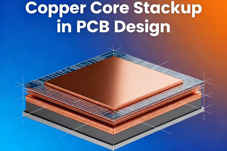
Type 2 - Copper Core LED PCB
What is Copper Core LED PCB?
When aluminum LED PCBs reach their thermal limits, copper core LED PCBs step in as the premium solution. These high-performance boards utilize pure copper as the base substrate instead of aluminum, delivering thermal conductivity 2-4 times superior to their aluminum counterparts.
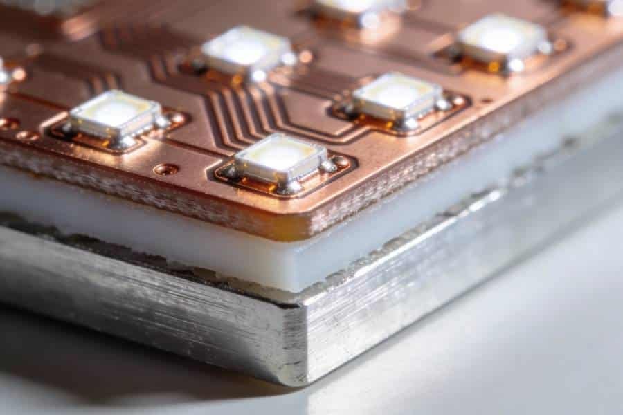
Copper core LED PCBs target the upper tier of LED applications where power density, reliability, and thermal performance are paramount—and budget takes a back seat to performance. The construction mirrors aluminum LED PCBs with three layers, but the copper base fundamentally changes the thermal equation.
The layered structure includes:
- Copper Base Layer (1.0-3.0mm thick): High-purity copper (99.9%+) providing exceptional heat spreading
- Thermally Conductive Dielectric Layer (50-150μm): Advanced dielectric materials optimized for copper substrates
- Copper Circuit Layer (1-3oz): Thicker copper traces often used due to higher current requirements
The critical difference lies in copper’s intrinsic thermal conductivity—approximately 385-400 W/mK for the base material compared to aluminum’s 120-180 W/mK. This means heat spreads across copper bases much faster, enabling higher LED power densities and more uniform temperature distribution across the board.
Technical Specifications
| Parameter | Value |
|---|---|
| Thermal Conductivity | 3.0-8.0 W/mK (through dielectric layer) |
| Copper Base Thermal Conductivity | 385-400 W/mK |
| Typical Board Thickness | 1.0mm, 1.5mm, 2.0mm, 2.5mm, 3.0mm |
| Dielectric Layer Thickness | 50μm, 75μm, 100μm, 150μm |
| Copper Circuit Layer | 1oz, 2oz, 3oz, 4oz (up to 140μm) |
| Operating Temperature Range | -55°C to +150°C |
| Dielectric Breakdown Voltage | >3500V |
| Thermal Resistance | 0.2-1.5 °C/W (varies with area) |
| Coefficient of Thermal Expansion | 17-18 ppm/°C |
Advantages of Copper Core LED PCB
- Superior Thermal Conductivity
Copper’s thermal performance stands unmatched among common metal substrates. The 3-8 W/mK through-layer thermal conductivity enables copper core PCBs to handle extreme LED power densities that would overwhelm aluminum boards. Applications using 10W+ LEDs or densely packed LED arrays benefit enormously from this enhanced heat spreading capability. - Extended LED Lifespan
Better thermal management directly translates to longer LED operational life. By maintaining lower junction temperatures, copper core PCBs can extend LED lifespan by 50-100% compared to aluminum implementations of the same design. For applications where LED replacement is costly or difficult (stadium lighting, industrial high-bays), this longevity justifies the premium cost. - Handles Higher Power Densities
Copper core boards comfortably support 15-20W per LED, whereas aluminum typically maxes out around 5W per LED without external cooling. This enables more compact, brighter lighting designs with fewer LED components—often offsetting the higher PCB cost through reduced LED count. - Exceptional Thermal Stability
Under continuous high-power operation, copper maintains more uniform temperature distribution across the board. This prevents hot spots, ensures consistent LED performance across all positions, and maintains uniform color temperature—critical for professional lighting applications. - Improved High-Temperature Performance
Copper’s higher melting point and thermal stability enable reliable operation in elevated ambient temperatures up to 150°C. Industrial environments, engine compartments, and other high-temperature locations demand this enhanced capability. - Better CTE Matching
Copper’s coefficient of thermal expansion (17-18 ppm/°C) more closely matches LED dies and many component packages compared to aluminum (23-26 ppm/°C). This reduces thermal stress during temperature cycling, improving solder joint reliability and reducing thermal fatigue failures. - Lower Thermal Resistance
The combination of high thermal conductivity and good CTE matching results in lower overall thermal resistance (junction-to-ambient). This means less temperature rise per watt of heat, enabling more aggressive LED drive currents for maximum brightness.
Disadvantages
- Significantly Higher Cost
Copper core LED PCBs cost 2-3 times more than equivalent aluminum boards. Material costs are higher, and manufacturing requires more specialized processes. For cost-sensitive consumer products or high-volume production, this premium often proves prohibitive. - Heavier Weight
Copper’s density (8.96 g/cm³) makes copper core boards approximately 3.3x heavier than aluminum equivalents. Automotive, aerospace, and portable applications where weight optimization matters face challenges. Mounting structures must support greater loads, and shipping costs increase. - Oxidation and Corrosion Concerns
Copper oxidizes more readily than aluminum, forming copper oxide that impairs thermal performance. Copper core PCBs require protective coatings or surface treatments to prevent degradation—adding processing steps and cost. Humid environments accelerate corrosion without proper protection. - More Complex Manufacturing
Drilling, routing, and processing copper bases require specialized tooling due to copper’s material properties. Many PCB manufacturers lack the equipment or expertise for copper core fabrication, limiting supplier options and increasing lead times. - Thermal Management Overkill
For applications using LEDs under 3W each, copper’s superior thermal performance provides minimal practical benefit over aluminum. The cost premium becomes unjustifiable when aluminum adequately manages thermal loads—making copper inefficient for low-to-medium power designs. - Higher Thermal Mass
Copper’s heat capacity means copper core boards take longer to reach thermal equilibrium. For LED systems that cycle on/off frequently, this thermal lag can be a disadvantage compared to aluminum’s faster response.
Best Applications for Copper Core LED PCB
- High-Power LED Modules
Single LEDs exceeding 5W or LED clusters dissipating 50W+ per square inch benefit from copper’s thermal capabilities. These applications include industrial task lighting, sports field illumination, and specialized scientific lighting where maximum brightness is essential. - Stage and Studio Lighting
Professional entertainment lighting—spotlights, moving heads, PAR cans, and wash lights—demands reliable performance under continuous high-power operation. Copper core PCBs ensure consistent color temperature and maximum output through extended performance sessions where lighting failure would be catastrophic. - Automotive High-Intensity Headlights
Modern automotive LED and laser-diode headlights generate extreme heat in confined spaces. Copper core boards manage these thermal challenges while withstanding vibration, temperature cycling, and harsh environmental conditions. The reliability justifies premium costs in safety-critical applications. - Industrial High-Bay Lighting
Warehouse, factory, and manufacturing facility high-bay fixtures operating 24/7 at heights of 20-40 feet make LED replacement expensive and disruptive. Copper core PCBs maximize operational lifespan, reducing maintenance frequency and improving total cost of ownership despite higher initial investment. - Laser Diode Applications
High-power laser diodes for industrial cutting, medical devices, and optical pumping generate significant heat in tiny packages. Copper core boards provide the thermal stability required for maintaining laser wavelength precision and preventing thermal runaway. - Concentrated LED Arrays
Applications packing many LEDs into small areas—such as miniature projectors, automotive adaptive lighting, or high-intensity searchlights—create challenging heat densities. Copper’s superior thermal spreading prevents hotspots that would cause premature failure. - Server and Data Center Lighting
Data centers using LED lighting in hot-aisle/cold-aisle configurations face elevated ambient temperatures. Copper core boards maintain LED reliability in these thermally challenging environments while eliminating maintenance in difficult-to-access ceiling spaces.
Copper vs Aluminum: Decision Matrix
Choose Copper Core When:
- LED power exceeds 5W per component
- Power density exceeds 10W per square inch
- Ambient operating temperature routinely exceeds 50°C
- LED replacement is extremely difficult or costly
- Application demands maximum reliability
- Product failure carries severe consequences
- Budget accommodates 2-3x PCB cost premium
Choose Aluminum When:
- LED power remains under 5W per component
- Power density stays below 8W per square inch
- Standard operating temperatures prevail
- Cost optimization is important
- Weight reduction matters
- High production volumes required
- Thermal performance requirements fall within aluminum’s capabilities
For personalized recommendations on whether copper core justifies the investment for your specific application, consult our Technical Capabilities team for expert analysis.
Copper Core LED PCB Cost Analysis
Copper core LED PCBs typically range $6-$25 per board depending on:
- Board size and copper thickness
- Dielectric material type
- Surface finishing requirements
- Copper weight in circuit layer
- Additional protective coatings
- Order quantity
Volume Pricing Example:
- 10 boards: $18-25 each
- 100 boards: $10-15 each
- 1000 boards: $6-10 each
While expensive compared to aluminum, copper core boards often enable designs impossible with other substrates. The performance justifies costs when thermal requirements exceed aluminum’s capabilities or when extended lifespan reduces total ownership costs.
Type 3 - FR4 LED PCB (Standard PCB Material)
What is FR4 LED PCB?
FR4 LED PCBs represent the most common printed circuit board substrate globally, consisting of woven fiberglass fabric impregnated with flame-retardant epoxy resin. FR4 (Flame Retardant 4) earned its ubiquity in general electronics through low cost, excellent electrical properties, and mature manufacturing processes available worldwide.
For LED applications, FR4 serves a specific niche: low-power LEDs where thermal demands remain modest. While thermal performance significantly lags behind metal core substrates, FR4’s unbeatable cost and manufacturing accessibility make it the default choice when LEDs generate minimal heat.
The standard FR4 board structure includes:
- FR4 Core Material: Fiberglass-reinforced epoxy forming the insulating base
- Copper Layers: Typically 1-2oz copper on top (and bottom for double-sided boards)
- Solder Mask: Protective coating over copper traces
- Silkscreen: Component labels and markings
Unlike aluminum or copper core boards with thermally conductive dielectrics, FR4 is an electrical insulator that also insulates thermally—blocking rather than conducting heat. This fundamental limitation restricts FR4 LED PCBs to applications where total heat generation stays minimal.
Technical Specifications
| Parameter | Value |
|---|---|
| Thermal Conductivity | 0.3-0.4 W/mK (10-20x lower than aluminum) |
| Typical Board Thickness | 0.4mm, 0.6mm, 0.8mm, 1.0mm, 1.6mm, 2.0mm |
| Glass Transition Temp (Tg) | 130-180°C (material dependent) |
| Copper Layer Options | 0.5oz, 1oz, 2oz, 3oz |
| Operating Temperature Range | -40°C to +130°C |
| Dielectric Breakdown Voltage | >3000V |
| Thermal Resistance | 10-50 °C/W (extremely high) |
| Coefficient of Thermal Expansion | 14-17 ppm/°C (in-plane), 50-70 ppm/°C (z-axis) |
| Moisture Absorption | <0.1% |
Advantages of FR4 LED PCB
Lowest Cost Option
FR4 represents the most economical PCB substrate available. Standard FR4 boards cost 50-80% less than aluminum LED PCBs, making them attractive for budget-constrained consumer products, disposable electronics, or applications where LED heat generation is negligible.
Universal Manufacturing Availability
Every PCB fabricator worldwide supports FR4 manufacturing. This ubiquity ensures:
- Shortest possible lead times (24-48 hours for rush orders)
- Competitive pricing from numerous suppliers
- Easy sourcing for prototype and production quantities
- No specialized equipment or processes required
Supports Complex Multi-Layer Designs
Unlike metal core boards limited to single or double-layer construction, FR4 easily accommodates 4, 6, 8, or more layers. LED applications requiring complex control circuitry, sensors, wireless modules, or microcontrollers alongside LEDs benefit from this flexibility.
Excellent Electrical Properties
FR4 provides superior electrical insulation and stable dielectric constant across frequency ranges. For LED drivers integrated on the same board as LEDs, or for LED displays with control electronics, FR4’s electrical characteristics simplify circuit design.
Lightweight and Thin
Standard 1.6mm FR4 boards weigh significantly less than metal core alternatives. Thickness options down to 0.4mm enable ultra-slim LED applications like smartphone backlights, laptop keyboard lighting, or thin signage panels.
Established Design Rules
Decades of FR4 use means mature design tools, extensive component libraries, and well-understood manufacturing constraints. Engineers can design FR4 LED PCBs confidently using familiar workflows without learning metal core-specific requirements.
Easy Rework and Modification
FR4 boards can be easily cut, drilled, or modified after manufacturing. Prototyping and testing iterations proceed quickly. Component rework using standard soldering equipment presents no challenges—unlike metal core boards requiring special handling.
Disadvantages
Poor Thermal Management
FR4’s thermal conductivity (0.3-0.4 W/mK) is woefully inadequate for medium or high-power LEDs. Heat builds up rapidly at LED junctions, causing immediate performance degradation and shortened lifespan. This limitation strictly confines FR4 to low-power applications.
Severe Power Limitations
Individual LEDs on FR4 should rarely exceed 0.5W, and total power density must stay below 2-3W per square inch. Exceeding these limits causes destructive thermal runaway where LED heat generation accelerates degradation in a self-reinforcing cycle.
Requires External Heat Management
FR4 LED applications often require external heat sinks, thermal pads, or metal mounting plates to conduct heat away from the PCB. These additional components negate some of FR4’s cost advantage while adding assembly complexity.
Reduced LED Lifespan
Elevated operating temperatures inherent to FR4’s poor thermal conductivity accelerate LED degradation. An LED rated for 50,000 hours on aluminum MCPCB might last only 10,000-20,000 hours on FR4—requiring more frequent replacements and increasing total cost of ownership.
Performance Degradation
LEDs operating at higher junction temperatures experience:
- Reduced light output (10-30% less brightness)
- Color shift toward longer wavelengths
- Inconsistent performance across LED arrays
- Visible dimming over time
Higher Z-Axis CTE
FR4’s coefficient of thermal expansion in the thickness direction (z-axis) significantly exceeds that of LED components. Temperature cycling creates mechanical stress on solder joints and components, increasing failure risk in thermally dynamic environments.
Best Applications for FR4 LED PCB
- Indicator LEDs and Status Lights
Dashboard indicators, equipment status LEDs, power-on indicators, and diagnostic lights typically use small LEDs well under 0.1W. FR4 handles these trivial thermal loads perfectly while keeping costs minimal. - Low-Power Displays
Small LED matrix displays, 7-segment displays, and dot-matrix signs with individual LED currents under 20mA per segment work well on FR4. Calculator displays, microwave oven displays, and simple signage exemplify appropriate applications. - Consumer Electronics Backlighting
Smartphone displays, tablet screens, laptop keyboards, and remote control button backlighting use tiny LEDs generating minimal heat. The compact form factor and cost sensitivity of these products align perfectly with FR4’s strengths. - Decorative and Accent Lighting
LED strips for under-cabinet lighting, holiday decorations, mood lighting, and architectural accents often use many low-power LEDs. When individual LED wattage stays minimal, FR4 provides cost-effective support for these aesthetic applications. - Indoor Signage
Small indoor LED signs, point-of-purchase displays, and directional signage in climate-controlled environments can use FR4 when LED power stays low. The controlled temperature environment helps compensate for FR4’s thermal limitations. - Prototyping and Testing
Engineers often use FR4 for initial LED circuit prototypes due to quick turnaround times and low costs. Testing different LED configurations, drive currents, and optical designs happens quickly with FR4 before committing to metal core production boards. - Budget-Sensitive Consumer Products
Toys, novelty items, promotional products, and disposable electronics where cost absolutely dominates purchasing decisions can use FR4 with extremely low-power LEDs. When retail price points allow only pennies for PCB costs, FR4 becomes the only viable option.
FR4 LED PCB Design Considerations
When FR4 is your only option due to budget or complexity requirements, follow these design practices to maximize performance:
- Maximize Copper Pour Areas
Use solid copper fills under and around LED components wherever possible. Thicker copper (2oz instead of 1oz) improves lateral heat spreading. While FR4 itself conducts heat poorly, copper layers can spread heat before it saturates the FR4 substrate. - Strategic Thermal Via Placement
Place multiple thermal vias (0.3-0.5mm diameter) directly under LED pads. These vias conduct heat through the FR4 to bottom copper layers or mounting surfaces. Use 4-8 thermal vias per LED component for best results. - Keep LED Power Minimal
Strictly limit individual LED power to 0.5W maximum, with 0.2-0.3W being safer for long-term reliability. When more light is needed, use multiple lower-power LEDs rather than fewer high-power LEDs. - Add Metal Mounting Plates
Design FR4 LED boards to mount on aluminum or steel plates that act as heat sinks. Thermal interface material (TIM) between board and plate improves heat transfer. The mounting plate becomes the primary thermal management solution. - Monitor Junction Temperature
During prototyping, measure LED junction temperature under worst-case conditions (maximum ambient temperature, maximum drive current). Keep junction temperature below 85°C for adequate lifespan. - Consider Ventilation
Ensure LED products using FR4 PCBs have adequate airflow. Natural or forced convection dramatically improves heat dissipation when substrate thermal conductivity is limited.
FR4 LED PCB Cost Analysis
FR4 LED PCBs represent the most economical option:
- Single boards: $1-3 each
- Small quantities (10-50): $0.50-1.50 each
- Production volumes (1000+): $0.10-0.50 each
Volume pricing drops dramatically due to automated manufacturing and commodity material costs. For consumer products requiring tens of thousands of boards, FR4’s cost advantage becomes overwhelming when thermal requirements permit its use.
Type 4 - Ceramic LED PCB
What is Ceramic LED PCB?
Ceramic LED PCBs represent the ultimate performance substrate for LED applications demanding uncompromising reliability, extreme thermal management, or operation in harsh environments. Using advanced ceramic materials—primarily Aluminum Oxide (Al₂O₃) or Aluminum Nitride (AlN)—as the base substrate, these premium boards deliver specifications unattainable with metal core or FR4 alternatives.
Ceramic substrates combine three critical properties simultaneously:
- Exceptional thermal conductivity rivaling or exceeding copper
- Superior electrical insulation enabling high-voltage operation
- Extreme temperature capability supporting operation beyond 300°C
This unique combination makes ceramic LED PCBs the choice for aerospace, military, medical, and industrial applications where failure is not an option and cost takes secondary priority to performance and reliability.
Ceramic Material Types
Aluminum Oxide (Al₂O₃) – Alumina Ceramic
The more common and economical ceramic option, aluminum oxide offers excellent thermal and electrical properties at moderate cost. Alumina ceramic (typically 96% or 99.6% purity) provides thermal conductivity of 20-30 W/mK—significantly better than metal core PCBs while maintaining outstanding electrical insulation.
Aluminum Nitride (AlN) – Advanced Ceramic
Premium aluminum nitride ceramic delivers extraordinary thermal conductivity of 150-180 W/mK—approaching the thermal performance of pure copper while retaining ceramic’s electrical insulation properties. AlN represents the absolute top tier of LED PCB substrates, used when no other material meets requirements.
Technical Specifications
| Parameter | Al₂O₃ (Alumina) | AlN (Aluminum Nitride) |
|---|---|---|
| Thermal Conductivity | 20-30 W/mK | 150-180 W/mK |
| Dielectric Strength | 10-20 kV/mm | 14-16 kV/mm |
| Dielectric Constant | 9-10 | 8-9 |
| Operating Temperature | -55°C to +300°C | -55°C to +350°C |
| Flexural Strength | 300-400 MPa | 300-350 MPa |
| CTE | 6-7 ppm/°C | 4-5 ppm/°C |
| Thermal Resistance | 0.1-0.8 °C/W | 0.05-0.3 °C/W |
| Relative Cost | $$$$$ | $$$$$$ |
Advantages of Ceramic LED PCB
- Unmatched Thermal Conductivity (AlN)
Aluminum nitride ceramic approaches copper’s thermal performance while maintaining electrical insulation. This enables ceramic LED PCBs to handle power densities impossible for any other substrate—supporting 20W+ per LED or extreme LED packing densities without thermal failure. - Superior Electrical Insulation
Ceramic materials provide dielectric breakdown voltages exceeding 10 kV/mm—far superior to metal core PCB dielectric layers. High-voltage LED applications, UV LED systems requiring high drive voltages, and applications needing maximum electrical safety benefit from this insulation capability. - Extreme Temperature Capability
Ceramic LED PCBs operate reliably from -55°C to +350°C—temperatures that would destroy FR4, melt solder on aluminum PCBs, or cause metal core dielectric failure. Engine compartment lighting, industrial furnace monitoring, and aerospace applications demand this temperature range. - Outstanding Long-Term Reliability
Ceramic’s chemical stability, resistance to degradation, and imperviousness to environmental factors enable operational lifespans exceeding 100,000 hours even under demanding conditions. For installations where LED replacement is prohibitively expensive or dangerous, ceramic justifies premium costs through extreme longevity. - Excellent CTE Matching
Ceramic’s coefficient of thermal expansion closely matches LED semiconductor dies and many component packages. This matching minimizes thermal stress during temperature cycling, reducing solder joint fatigue and extending component lifespan—particularly important for high-reliability applications. - Chemical and Corrosion Resistance
Unlike metals that oxidize or corrode, ceramic materials resist virtually all chemicals, solvents, and environmental contaminants. Harsh industrial environments, marine applications, and chemical processing facilities benefit from ceramic’s imperviousness to degradation. - Hermetic Sealing Possible
Ceramic substrates enable hermetically sealed LED packages protecting sensitive components from moisture, contaminants, and atmospheric exposure. Medical devices, military equipment, and precision optical systems utilize this capability. - High-Frequency Performance
Ceramic’s stable dielectric properties and low loss tangent make it excellent for RF and microwave applications. LED systems integrated with wireless communications or high-frequency electronics benefit from ceramic’s superior electrical characteristics.
Disadvantages
Extremely High Cost
Ceramic LED PCBs cost 5-10 times more than aluminum equivalents, with AlN boards reaching 15-20x aluminum pricing. Material costs, specialized manufacturing processes, and lower production volumes all contribute. This premium restricts ceramic to applications where performance absolutely justifies expense.
Brittle Material
Ceramic’s mechanical brittleness makes it susceptible to cracking from impact, dropping, or mechanical stress. Applications involving vibration, shock, or rough handling require careful mechanical design and protective packaging. Rework becomes nearly impossible without destroying the board.
Complex Manufacturing
Ceramic PCB fabrication requires specialized equipment, processes, and expertise unavailable at most PCB manufacturers. This limitation means:
- Longer lead times (often 4-8 weeks)
- Fewer supplier options
- Higher minimum order quantities
- Limited design iteration speed
Difficult to Machine
Drilling, cutting, and routing ceramic requires diamond tooling and specialized machining processes. Tool wear is high, processing is slow, and dimensional tolerances are more difficult to hold compared to metal or FR4 substrates.
Cannot be Reworked
Once components are soldered to ceramic substrates, rework is extremely challenging. The brittleness and high temperature resistance make standard rework techniques risky. Failed assemblies often must be scrapped rather than repaired, increasing overall costs.
Limited Design Flexibility
Ceramic PCBs typically support fewer layers and design options compared to FR4 multilayer boards. Complex circuits requiring numerous interconnect layers face constraints, often necessitating hybrid approaches combining ceramic LED areas with FR4 control circuitry.
Thermal Shock Sensitivity
Despite high-temperature capability, ceramic can crack from rapid temperature changes (thermal shock). Designs must manage heating and cooling rates carefully to prevent fracture—particularly relevant for LEDs that cycle on/off rapidly.
Best Applications for Ceramic LED PCB
- Medical Equipment and Surgical Lighting
Operating room lights, surgical microscope illumination, diagnostic equipment, and medical imaging devices use ceramic LED PCBs for reliability, sterilization compatibility, and long operational life. Medical applications justify premium costs through patient safety and equipment uptime requirements. - Aerospace and Aviation Lighting
Aircraft interior lighting, cockpit instruments, exterior navigation lights, and runway approach systems operate in extreme temperature ranges (-55°C to +85°C or higher) with demanding vibration and reliability specifications. Ceramic boards meet aerospace certification requirements while providing 20+ year service life. - Military and Defense Applications
Military vehicles, weapons systems, night vision equipment, and field-deployable electronics require LED systems that function reliably in combat conditions. Ceramic’s ruggedness, temperature range, and immunity to environmental factors make it essential for defense applications. - High-Power LED Systems
LED grow lights using 20W+ LEDs, industrial UV curing systems, laser diode pumping applications, and concentrated solar LED systems generate extreme power densities requiring ceramic’s thermal capabilities. No other substrate handles these power levels reliably. - Harsh Environment Industrial Lighting
Petrochemical facilities, mining operations, steel mills, and industrial furnaces expose lighting to extreme temperatures, chemicals, vibration, and contaminants. Ceramic LED PCBs survive where other substrates fail, reducing maintenance and improving safety. - Long-Life Infrastructure Installations
Street lighting, tunnel lighting, bridge illumination, and architectural lighting where replacement requires road closures, traffic disruption, or specialized access equipment benefit from ceramic’s multi-decade lifespan. Initial cost premium pays off through eliminated maintenance. - UV LED Applications
UV sterilization systems, UV curing for printing and coatings, phototherapy equipment, and scientific UV light sources operate at elevated temperatures while generating significant heat. Ceramic’s high-temperature capability and thermal management make it ideal for UV LED systems. - Precision Optical Systems
Laser diode collimation, fiber optic illumination, machine vision lighting, and scientific instrumentation require thermally stable LED placement maintaining precise optical alignment. Ceramic’s low CTE and dimensional stability ensure optical performance consistency.
When Ceramic Justifies Premium Cost
- Application Requires 20+ Year Lifespan
When LED replacement costs exceed ceramic PCB premium by factors of 10x or more, ceramic’s longevity justifies initial investment through eliminated maintenance and downtime. - Operating Temperature Exceeds 150°C
Ambient temperatures or LED power dissipation creating board temperatures above aluminum’s limits necessitate ceramic’s extreme temperature capability. - Maximum Thermal Performance is Mandatory
Power densities exceeding 15-20W per LED or thermal requirements beyond copper core capabilities demand AlN ceramic’s extraordinary thermal conductivity. - Electrical Isolation is Critical
High-voltage LED systems, applications requiring maximum electrical safety, or designs needing superior insulation specifications benefit from ceramic’s dielectric properties. - Product Failure Has Severe Consequences
Safety-critical applications, medical devices, aerospace systems, and installations where failure endangers lives justify ceramic’s superior reliability through risk mitigation. - Environmental Conditions Are Extreme
Chemical exposure, temperature extremes, humidity, salt fog, radiation, or combinations of harsh factors require ceramic’s comprehensive environmental resistance.
Ceramic LED PCB Cost Analysis
Ceramic LED PCB pricing varies dramatically based on material and specifications:
Aluminum Oxide (Al₂O₃):
- Small quantities (10-50): $20-40 per board
- Production (100-500): $12-25 per board
- Volume (1000+): $8-15 per board
Aluminum Nitride (AlN):
- Small quantities (10-50): $50-100 per board
- Production (100-500): $30-60 per board
- Volume (1000+): $20-40 per board
These prices assume modest board sizes (50-100cm²). Larger boards, complex patterns, or specialized surface finishes increase costs further. NRE (Non-Recurring Engineering) charges for custom ceramic tooling can add $1000-5000 to initial orders.
Type 5 - Flexible LED PCB
What is Flexible LED PCB?
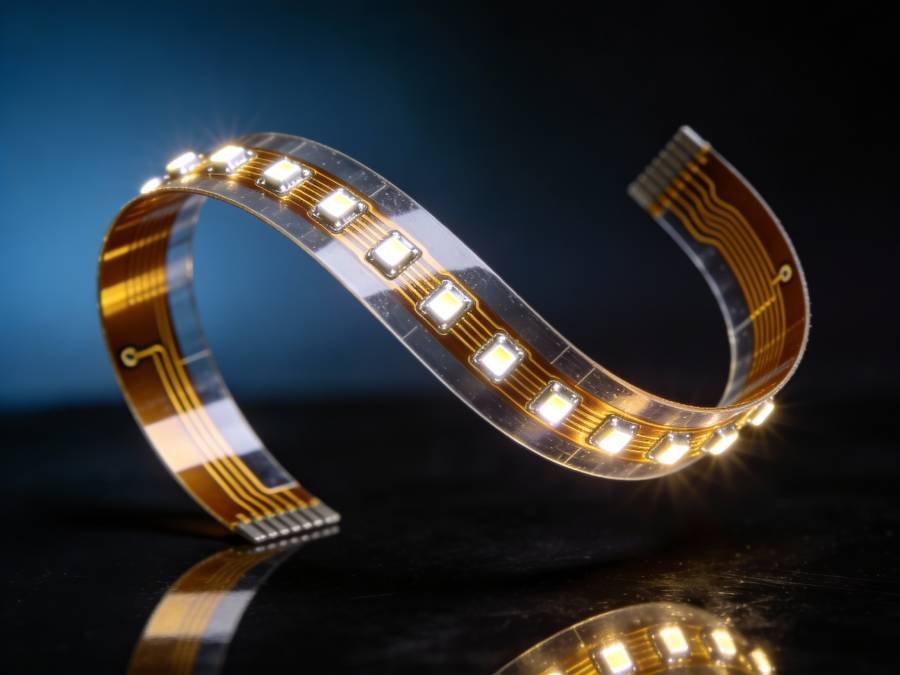
Flexible LED PCBs revolutionize LED applications by enabling circuits that bend, fold, and conform to curved surfaces—opening design possibilities impossible with rigid substrates. Using flexible polymer films as the base material, these boards trade thermal performance for mechanical flexibility, creating unique form factors for wearable technology, curved displays, automotive interior lighting, and innovative consumer products.
The flexible substrate typically consists of:
- Polyimide (PI) – Premium flexible material with superior temperature resistance
- Polyester (PET) – Economical flexible material for lower-temperature applications
Both materials allow the PCB to flex repeatedly without breaking, though they share FR4’s thermal limitations—restricting flexible LED PCBs to low-power applications where heat generation stays minimal.
Flexible Substrate Materials
Polyimide (PI) – Premium Flexible Material
Polyimide offers exceptional temperature resistance (-200°C to +250°C), good chemical resistance, and stable electrical properties. Its superior thermal performance compared to polyester makes it the preferred choice for flexible LED applications requiring higher temperature tolerance or better dimensional stability.
Polyester (PET) – Economical Flexible Option
Polyester provides adequate flexibility at significantly lower cost than polyimide. Its operating temperature range (-70°C to +105°C) suffices for many consumer applications, though it lacks polyimide’s high-temperature capability and long-term stability.
Technical Specifications
| Parameter | Polyimide (PI) | Polyester (PET) |
|---|---|---|
| Thermal Conductivity | 0.12-0.3 W/mK | 0.15-0.2 W/mK |
| Operating Temperature | -200°C to +250°C | -70°C to +105°C |
| Typical Thickness | 0.025mm – 0.125mm | 0.05mm – 0.2mm |
| Dielectric Constant | 3.4-3.5 | 3.0-3.2 |
| Dielectric Breakdown | 3-7 kV/mm | 5-10 kV/mm |
| Tensile Strength | 165-231 MPa | 55-172 MPa |
| Elongation at Break | 70-100% | 100-150% |
| Bend Radius | 10x thickness | 10x thickness |
| Relative Cost | $$$ | $$ |
Advantages of Flexible LED PCB
- Conforms to Curved Surfaces
Flexible PCBs naturally conform to three-dimensional shapes, cylinders, and irregular contours impossible for rigid boards. Automotive dashboards, curved architectural features, cylindrical pillars, and wearable devices benefit from this unique capability. - Bendable and Foldable
The substrate can bend to tight radii (typically 10x the board thickness) and fold completely without damage. This enables creative lighting installations, compact packaging, and deployable LED systems that unfold when needed. - Ultra-Lightweight and Thin
Flexible LED PCBs weigh a fraction of rigid alternatives and measure as thin as 0.025mm. Weight-critical applications like drones, aerospace interior lighting, and wearable electronics benefit from minimal mass addition. - Shock and Vibration Resistant
The flexible nature absorbs shock and vibration rather than transmitting stress to solder joints and components. This mechanical compliance reduces failures in high-vibration environments like automotive applications or industrial equipment. - Eliminates Connectors and Wiring
Flexible PCBs can replace bulky wire harnesses and multiple board-to-board connectors by creating continuous circuits that flex between rigid sections. This reduces assembly time, failure points, and overall system weight. - Design Freedom and Innovation
Flexible LED PCBs enable lighting designs previously impossible—LED clothing that moves with the wearer, foldable LED lamps, contoured display backlights, and artistic installations where rigid PCBs would be visible or impractical. - Compact Packaging
Flexible boards fold or roll for efficient storage and shipping. Products can package in smaller volumes, reducing shipping costs and enabling more compact final form factors. - Reduced Assembly Steps
Single flexible PCBs can replace multiple rigid boards connected by wires, reducing assembly labor, potential error points, and manufacturing complexity.
Disadvantages
- Poor Thermal Dissipation
Flexible substrates share FR4’s thermal limitations with conductivity of only 0.12-0.3 W/mK. This severely restricts LED power—typically limiting individual LEDs to 0.3-0.5W maximum and requiring careful thermal design even at these low power levels. - Strictly Low-Power Applications
The combination of poor thermal conductivity and thin substrate construction means flexible LED PCBs can only support very low-power LEDs. Applications requiring bright illumination must use many small LEDs rather than fewer high-power components. - Higher Cost Than FR4
Flexible PCB manufacturing requires specialized processes, materials, and handling compared to standard FR4 production. Costs typically run 50-150% higher than equivalent rigid FR4 boards, though still far below metal core pricing. - Mechanical Durability Concerns
While flexible substrates handle bending well, they’re vulnerable to tearing, puncture, and abrasion damage. Exposed flexible circuits require protective coverlays or housings. Repeated flexing in the same location can cause fatigue failures over time. - Limited Mechanical Support
Flexible PCBs lack rigid substrates’ mechanical rigidity. Component mounting often requires stiffeners or backing plates to prevent excessive flexing during assembly and operation. Large or heavy components may require transition to rigid sections. - Assembly Challenges
Handling flexible PCBs during manufacturing requires special fixtures and processes. Automated assembly equipment designed for rigid boards may need modification. Component placement accuracy can be challenging on non-rigid substrates. - Design Complexity
Designing flexible circuits requires additional considerations: bend radii calculations, strain relief, stiffener placement, and flex cycle life analysis. This increases engineering time and complexity compared to rigid board designs. - Temperature Limitations (PET)
Polyester-based flexible PCBs can’t withstand standard lead-free soldering temperatures (260°C+), requiring low-temperature solders, conductive adhesives, or specialized assembly processes that increase costs and complexity.
Best Applications for Flexible LED PCB
- Wearable Technology
Smart clothing with integrated LED lighting, fitness trackers with LED displays, smartwatch displays, and medical monitoring devices with LED indicators leverage flexible PCBs’ conformability and light weight. The boards flex naturally with body movement without failure. - Automotive Interior Lighting
Contoured dashboard lighting, door panel ambient illumination, curved instrument cluster backlights, and headliner mood lighting conform to automotive interior surfaces using flexible LED PCBs. The vibration resistance ensures long-term reliability in vehicle environments. - Curved and Flexible Displays
Flexible OLED displays, curved LED video screens, cylindrical column displays, and bendable signage use flexible LED PCBs for both the display elements and backlighting. The substrate conforms to the display curvature maintaining uniform appearance. - Medical and Healthcare Devices
Wearable medical monitors, flexible diagnostic equipment lighting, curved surgical instrument illumination, and patient monitoring devices employ flexible LED PCBs. The biocompatibility of properly encapsulated flexible circuits suits medical applications. - Consumer Electronics
Foldable smartphones with flexible displays, rollable tablet screens, curved television backlights, and laptop keyboard backlighting use flexible LED PCBs. Consumer products benefit from the innovative form factors enabled by flexible technology. - Decorative and Architectural Lighting
Artistic light installations, architectural accent lighting conforming to building contours, sculptural illumination, and museum display lighting leverage flexible PCBs’ unique aesthetic possibilities. Designers appreciate the freedom to create lighting impossible with rigid boards. - Aerospace and Aviation
Aircraft cabin mood lighting conforming to curved fuselage walls, cockpit instrument backlighting, and space-constrained interior illumination utilize flexible LED PCBs’ light weight and conformability—critical in weight-sensitive aerospace applications. - Portable and Camping Lighting
Foldable LED lamps, rollable camping lights, flexible reading lights, and collapsible task lighting pack flat for storage using flexible LED PCBs. The durability handles repeated folding cycles consumers demand from portable products.
Flexible LED PCB Design Best Practices
- Use Polyimide for Higher Temperatures
When LEDs or operating environments exceed 105°C, specify polyimide substrates despite higher cost. Polyester’s temperature limitations cause failures in demanding applications. - Minimize LED Power
Keep individual LED power below 0.3W for reliable thermal management. When more illumination is needed, use multiple lower-power LEDs distributed across the flexible area rather than concentrated high-power LEDs. - Reinforce High-Stress Areas
Add local stiffeners at connector locations, component mounting areas, and attachment points. These prevent excessive flexing that could damage solder joints or components during assembly and use. - Avoid Components in Flex Zones
Place LEDs and components only in sections that remain static or flex minimally. Route traces through flex zones without components to maximize reliability during repeated flexing. - Design for Strain Relief
Provide adequate bend radii at transitions between rigid and flexible sections. Abrupt transitions concentrate stress and cause premature failures. Use curved transitions and relieved corners. - Distinguish Static vs Dynamic Flex
Static flex (bent once during installation) tolerates tighter radii and more components than dynamic flex (repeated bending during use). Design flex zones appropriately for the expected flex cycles. - Specify Protective Coverlay
Exposed flexible circuits need protective coverlay to prevent damage from handling, installation, and environmental exposure. This thin protective layer adds minimal thickness while significantly improving durability. - Plan for Thermal Management
Even with low-power LEDs, consider thermal design. Copper fills, thermal pathways to mounting surfaces, and adequate air circulation help prevent heat buildup in thermally limited flexible substrates.
Flexible LED PCB Cost Analysis
Flexible LED PCB pricing varies significantly based on material and complexity:
Polyimide (PI) Flexible PCBs:
- Prototype (1-10 boards): $15-35 per board
- Small production (50-100): $8-18 per board
- Volume (1000+): $3-8 per board
Polyester (PET) Flexible PCBs:
- Prototype (1-10 boards): $8-20 per board
- Small production (50-100): $4-12 per board
- Volume (1000+): $1.50-5 per board
Complex designs with multiple layers, stiffeners, or special features increase costs. NRE charges for flexible PCB tooling typically add $500-2000 to initial orders depending on complexity.
Type 6 - Hybrid LED PCB (Rigid-Flex Combination)
What is Hybrid LED PCB?
Hybrid LED PCBs strategically combine different substrate materials in a single integrated assembly, optimizing performance and cost by using the right material in each section. Rather than compromising with a single substrate that makes trade-offs across all requirements, hybrid designs place premium materials only where needed while using economical options elsewhere.
The most common hybrid configurations include:
- FR4 + Aluminum: Control circuitry on FR4, LED mounting areas on aluminum
- Rigid + Flexible: Rigid sections for components, flexible interconnections
- Aluminum + Copper: Standard LEDs on aluminum, high-power LEDs on copper zones
This sophisticated approach delivers optimized thermal management, design flexibility, and cost efficiency unattainable with single-material solutions—though at the cost of manufacturing complexity.
Common Hybrid Configurations
FR4 + Metal Core (Most Common)
Combines low-cost FR4 for control electronics, microcontrollers, and low-power circuitry with aluminum or copper zones for high-power LED mounting. The FR4 section handles complex circuit routing while metal core areas manage LED thermal loads.
Rigid-Flex LED PCB
Integrates rigid PCB sections (FR4 or metal core) containing components with flexible interconnecting sections. This eliminates connectors and wiring while enabling three-dimensional LED placement conforming to product housings.
Multi-Material Metal Core
Uses aluminum for standard power LEDs (1-3W) with embedded copper zones for high-power LEDs (>5W). This optimizes cost by limiting expensive copper to only areas requiring maximum thermal performance.
Ceramic + FR4 Hybrid
Mounts critical high-power or high-reliability LEDs on ceramic substrates while placing support circuitry on economical FR4. The hybrid approach gains ceramic’s benefits without bearing its cost across the entire board.
Technical Specifications
Hybrid LED PCB specifications vary dramatically based on the specific material combination. Key parameters depend on the constituent materials and their proportions:
| Parameter | Value Range |
|---|---|
| Thermal Conductivity | Variable by zone (0.3-180 W/mK) |
| Total Thickness | 0.4mm – 3.5mm (varies by section) |
| Operating Temperature | Determined by lowest-rated material |
| Cost Multiple vs Single Material | 1.5x – 4x depending on complexity |
| Manufacturing Lead Time | 2-4 weeks longer than standard |
| Minimum Order Quantity | Often higher (25-100 pieces) |
Advantages of Hybrid LED PCB
- Optimized Performance Per Zone
Each board section uses the optimal material for its specific function—premium thermal substrates only where heat generation demands it, flexible sections only where bending is required, and economical materials where basic functionality suffices. - Cost-Effective Compared to All-Premium
Using copper throughout an entire LED assembly might be prohibitively expensive. Hybrid designs limit copper to high-power LED zones while using aluminum or FR4 elsewhere, achieving 60-70% of copper’s benefits at 30-40% of its cost. - Design Flexibility and Integration
Hybrid boards consolidate what would otherwise require multiple separate PCBs connected by wires or connectors. This integration reduces assembly time, eliminates potential failure points, and enables more compact product designs. - Efficient Thermal Management
Strategic placement of high thermal conductivity materials exactly where LEDs generate the most heat optimizes thermal performance without unnecessary expense. Thermal simulation guides material selection for each zone. - Space Savings
Eliminating inter-board connectors and wiring harnesses by integrating functions on hybrid boards reduces overall product volume. Three-dimensional rigid-flex configurations fit complex enclosures more efficiently than multiple flat boards. - Complex Functionality Integration
Hybrid designs can incorporate LED arrays, driver electronics, wireless modules, sensors, and user interfaces on a single assembly. This system-level integration simplifies manufacturing and improves reliability by reducing interconnections. - Customizable for Specific Requirements
Hybrid approaches allow precise tailoring to application needs. Projects with unique thermal, mechanical, or electrical requirements can specify materials zone-by-zone rather than accepting compromises inherent in single-material solutions.
Disadvantages
- Significantly More Complex Manufacturing
Hybrid PCBs require specialized fabrication processes, multiple material handling steps, and careful process control. Not all PCB manufacturers possess the equipment, expertise, or willingness to produce hybrid designs—limiting supplier options. - Higher Engineering and Design Costs
Designing hybrid boards demands more engineering time for material selection, thermal analysis, mechanical simulation, and DFM (Design for Manufacturing) considerations. This increases project development costs and timeline. - Longer Lead Times
The specialized processes and lower production volumes typical for hybrid PCBs extend manufacturing lead times by 2-4 weeks compared to standard boards. Quick-turn prototypes become difficult or impossible. - Material Interface Reliability Concerns
Transitions between different substrate materials create potential reliability risks. Differing coefficients of thermal expansion can cause stress at interfaces during temperature cycling. Careful design and proper material selection mitigate but don’t eliminate these concerns. - Limited Supplier Availability
Many PCB manufacturers lack hybrid fabrication capabilities. This reduces competitive pricing options, potentially increases costs, and may limit design choices to what specific suppliers can produce. - Higher Minimum Order Quantities
Setup costs and process complexity often result in higher MOQs (25-100 pieces minimum) compared to standard PCBs where quantities of 5-10 are feasible. This increases prototyping costs. - More Complex Quality Control
Testing and inspection of hybrid boards requires verification of multiple material zones, interface integrity, and functional performance across different substrate types. This comprehensive testing increases manufacturing costs. - Design Iteration Challenges
Making changes to hybrid designs involves more complexity than single-material boards. What might be simple modifications on standard PCBs can require significant reengineering on hybrid assemblies, slowing development iterations.
Best Applications for Hybrid LED PCB
- Smart LED Lighting Systems
Products integrating high-power LEDs, driver electronics, microcontrollers, wireless modules, and sensors benefit from hybrid designs. The LED zones use metal core substrates while control circuitry uses FR4, combining optimal thermal management with complex circuit capability on a single assembly. - LED Drivers Integrated with Light Engines
Combining the LED driver power supply (requiring FR4 for complex circuitry) with the LED array (requiring metal core for thermal management) on a single hybrid board eliminates inter-board wiring, reduces assembly costs, and improves reliability. - Flexible-Rigid LED Displays
Curved displays requiring rigid sections for driver chips and control electronics with flexible sections conforming to display curvature utilize rigid-flex hybrid construction. This enables single-piece assemblies for curved televisions, automotive dashboards, and wearable displays. - Automotive Multi-Function Lighting
Modern automotive lights combining position lights, turn signals, daytime running lights, and high-beams in single assemblies use hybrid PCBs. Different LED functions have different power levels—hybrid designs optimize each zone’s substrate for its specific thermal requirements. - Architectural Lighting Fixtures
Custom architectural lighting requiring specific thermal zones for different LED groupings, integrated control electronics, and three-dimensional form factors leverage hybrid PCB capabilities. The design freedom enables lighting fixtures impossible with standard substrates. - Medical LED Devices
Medical equipment combining high-power examination LEDs (requiring ceramic or copper) with control circuitry, displays, and user interfaces (suited to FR4) benefits from hybrid integration. Single-assembly construction improves reliability and simplifies medical device certification. - IoT-Connected LED Products
Smart lighting, connected LED signage, and networked illumination systems integrate LEDs, wireless connectivity, sensors, and microcontrollers. Hybrid PCBs provide metal core LED zones alongside FR4 sections accommodating complex digital circuitry and RF components.
When to Consider Hybrid LED PCB
- Project Combines High-Power and Low-Power Zones
When some LEDs exceed 3W while others remain under 1W, hybrid designs place premium thermal substrates only where needed, optimizing cost-performance balance. - Need Flexibility in Some Areas, Rigidity in Others
Applications requiring three-dimensional LED placement with some sections conforming to curves while other areas remain flat benefit from rigid-flex hybrid construction. - Cost Optimization is Critical
When all-copper or all-ceramic would exceed budget but aluminum proves inadequate, strategic hybrid material placement achieves required performance at acceptable cost. - Space Constraints Demand Integration
Products where multiple separate PCBs connected by wires won’t fit physically can consolidate onto hybrid assemblies, reducing total volume through vertical integration. - Complex Multi-Function Requirements
Systems requiring LEDs plus drivers plus control electronics plus wireless connectivity benefit from hybrid’s ability to optimize substrate type for each functional zone.
Hybrid LED PCB Cost Analysis
Hybrid LED PCB pricing reflects increased complexity:
FR4 + Aluminum Hybrid:
- Prototype (5-25 boards): $15-35 per board
- Production (100-500): $8-18 per board
- Volume (1000+): $4-10 per board
Rigid-Flex LED PCB:
- Prototype (5-25 boards): $40-100 per board
- Production (100-500): $20-50 per board
- Volume (1000+): $10-25 per board
Complex Multi-Material:
- Prototype (10-50 boards): $50-150 per board
- Production (100-500): $25-75 per board
- Volume (1000+): $15-40 per board
NRE charges for hybrid PCB tooling and setup typically range $1000-5000 depending on complexity. Despite higher costs, system-level savings through eliminated connectors, wiring, and assembly steps often justify the premium.
Comprehensive Comparison: All 6 LED PCB Types
Understanding how all six LED PCB types compare across key specifications helps select the optimal substrate for your specific requirements:
Performance Comparison Table
| Specification | Aluminum | Copper | FR4 | Ceramic (Al₂O₃) | Ceramic (AlN) | Flexible | Hybrid |
|---|---|---|---|---|---|---|---|
| Thermal Conductivity | 1-2 W/mK | 3-8 W/mK | 0.3-0.4 W/mK | 20-30 W/mK | 150-180 W/mK | 0.12-0.3 W/mK | Variable |
| Max LED Power/Component | 1-5W | 5-15W | <0.5W | 10-20W | 20W+ | <0.5W | Variable |
| Operating Temp Range | -40 to 120°C | -55 to 150°C | -40 to 130°C | -55 to 300°C | -55 to 350°C | -70 to 250°C | Variable |
| Relative Cost | $$ | $$$ | $ | $$$$$ | $$$$$$ | $$-$$$ | $$-$$$$ |
| Cost Range per Board | $2-8 | $6-25 | $0.10-3 | $8-40 | $20-100 | $1.50-35 | $4-150 |
| Weight (Relative) | Medium | Heavy | Light | Medium | Medium | Very Light | Variable |
| Mechanical Form | Rigid | Rigid | Rigid | Rigid | Rigid | Flexible | Both |
| Typical Thickness | 1-3mm | 1-3mm | 0.4-2mm | 0.5-2mm | 0.5-2mm | 0.025-0.2mm | 0.4-3.5mm |
| Dielectric Strength | >3000V | >3500V | >3000V | 10-20 kV/mm | 14-16 kV/mm | 3-10 kV/mm | Variable |
| Expected Lifespan | 50,000+ hrs | 75,000+ hrs | 20,000-40,000 hrs | 100,000+ hrs | 100,000+ hrs | 30,000-50,000 hrs | Variable |
| Manufacturing Ease | Easy | Moderate | Very Easy | Difficult | Difficult | Moderate | Complex |
| Lead Time | 1-2 weeks | 2-3 weeks | 2-7 days | 4-8 weeks | 4-8 weeks | 2-3 weeks | 3-6 weeks |
| Design Complexity | Low | Low-Moderate | Very Low | Moderate | Moderate | Moderate-High | High |
| Reworkability | Moderate | Moderate | Easy | Very Difficult | Very Difficult | Difficult | Variable |
Application Suitability Matrix
| Application Type | Best Choice | Alternative | Avoid |
|---|---|---|---|
| Street Lighting | Aluminum | Copper | FR4, Flexible |
| Automotive Headlights | Copper, Aluminum | Ceramic | FR4, Flexible |
| Consumer LED Bulbs | Aluminum | FR4 (low-power) | Ceramic, Copper |
| Industrial High-Bay | Aluminum, Copper | Ceramic | FR4 |
| Indicator LEDs | FR4 | Aluminum | Ceramic, Copper |
| Medical Equipment | Ceramic, Copper | Aluminum | FR4 |
| Wearable Technology | Flexible | Hybrid Rigid-Flex | Rigid boards |
| Aerospace Lighting | Ceramic, Aluminum | Copper | FR4, Flexible |
| Stage/Studio Lighting | Copper | Ceramic | FR4, Flexible |
| Display Backlighting | FR4, Aluminum | Flexible | Ceramic |
| Architectural Features | Aluminum, Flexible | Hybrid | FR4 alone |
| IoT Smart Lighting | Hybrid | Aluminum + FR4 | Single material |
Selection Decision Tree
Step 1: Determine LED Power Requirements
- <0.5W per LED: Consider FR4 or Flexible
- 0.5-5W per LED: Choose Aluminum
- 5-15W per LED: Select Copper or Ceramic (Al₂O₃)
- >15W per LED: Specify Ceramic (AlN) or Copper
Step 2: Evaluate Environmental Conditions
- Standard indoor (-10 to +50°C): All options viable
- Automotive/Industrial (-40 to +85°C): Aluminum, Copper, Ceramic
- Extreme environments (>100°C or <-40°C): Ceramic only
Step 3: Consider Form Factor Requirements
- Must bend/flex: Flexible or Rigid-Flex Hybrid only
- Curved but static: Flexible, pre-formed rigid, or Hybrid
- Flat rigid: Any substrate appropriate
Step 4: Assess Budget Constraints
- Ultra-low cost (<$2/board): FR4 in volume
- Moderate budget ($2-10/board): Aluminum
- Performance priority ($10-30/board): Copper or Hybrid
- Premium/specialty (>$30/board): Ceramic
Step 5: Review Reliability Requirements
- Standard commercial (3-5 years): FR4, Aluminum
- Professional/Industrial (10-15 years): Aluminum, Copper
- Mission-critical (20+ years): Ceramic
Following this decision tree ensures selection of the most appropriate LED PCB substrate balancing performance, cost, and application requirements.
Frequently Asked Questions (FAQ)
Aluminum LED PCBs (MCPCBs) dominate the market, accounting for approximately 60-70% of all LED PCB applications. Their excellent balance of thermal performance, cost-effectiveness, and availability makes them the default choice for most commercial and industrial LED lighting projects.
FR4 is not recommended for LEDs exceeding 0.5W due to inadequate thermal management. While technically possible with extensive external heat sinking, the poor thermal conductivity (0.3-0.4 W/mK) causes excessive LED junction temperatures, dramatically reducing lifespan and performance. Choose aluminum or copper for high-power LEDs.
Properly designed aluminum LED PCBs typically achieve 50,000-60,000 hour LED lifespans under normal conditions. Ceramic LED PCBs can extend this to 100,000+ hours due to superior thermal management and dimensional stability. However, aluminum's lower cost often provides better total value when replacement is feasible.
Flexible LED PCBs can work outdoors with proper environmental protection. The substrate itself handles temperature extremes well (polyimide especially), but requires encapsulation or protective housing against moisture, UV exposure, and physical damage. Low LED power requirements limit brightness for outdoor visibility.
Copper core LED PCBs typically cost 2-3 times more than equivalent aluminum boards. A $5 aluminum MCPCB might cost $12-15 in copper. This premium is justified only when thermal requirements exceed aluminum's capabilities or when extended lifespan provides sufficient ROI.
Yes, hybrid designs can incorporate three or more substrate materials, though complexity increases costs and manufacturing challenges. Common tri-material hybrids include FR4 control sections, aluminum for standard LEDs, and copper zones for high-power LEDs—all on one integrated assembly.
Aluminum Nitride (AlN) ceramic provides the highest thermal conductivity at 150-180 W/mK, followed by copper core at 3-8 W/mK (through dielectric), then Aluminum Oxide ceramic at 20-30 W/mK. Standard aluminum MCPCBs offer 1-2 W/mK, while FR4 and flexible substrates provide only 0.3-0.4 W/mK.
Most LED PCB substrates are environmentally friendly. Aluminum is highly recyclable, copper recycling is well-established, and ceramic is chemically inert. FR4 contains some concerning materials but is RoHS compliant when properly manufactured. Flexible polyimide is more challenging to recycle but used in small quantities.
Yes, this is common practice. Many projects prototype with FR4 for quick, low-cost testing, then transition to aluminum or copper for production. However, thermal behavior differs significantly—ensure thorough testing with production substrates before committing to volume manufacturing.
Required certifications depend on application and market. Common requirements include: UL recognition for safety, RoHS compliance for environmental regulations, ISO 9001 for quality management, and IPC standards (IPC-6012 for rigid, IPC-6013 for flexible) for manufacturing quality. Medical, automotive, and aerospace applications have additional specific certifications.
Conclusion: Choosing the Right LED PCB for Your Project
Selecting the optimal LED PCB substrate fundamentally impacts your product’s performance, reliability, cost, and market success. As we’ve explored throughout this comprehensive guide, each of the six LED PCB types serves distinct applications where its unique characteristics provide maximum value.
Aluminum LED PCBs remain the workhorse of the industry—delivering reliable thermal management at accessible prices for the vast majority of LED lighting applications. When your LEDs stay below 5W each and operating environments remain within normal ranges, aluminum’s proven performance and cost-effectiveness make it the logical first choice.
Copper core LED PCBs step in when aluminum reaches its thermal limits. The 2-3x cost premium buys superior heat dissipation enabling brighter, more compact designs or extended lifespans in challenging thermal environments. High-power professional lighting, automotive headlights, and industrial applications justify copper’s investment.
FR4 LED PCBs serve the low-power segment where thermal demands stay minimal. Indicator lights, simple displays, and budget consumer products leverage FR4’s unbeatable economics and manufacturing convenience. Just respect its thermal limitations strictly to avoid premature failures.
Ceramic LED PCBs occupy the premium tier—delivering uncompromising performance for mission-critical applications where failure is unacceptable. Aerospace, medical, military, and extreme-environment installations justify ceramic’s 5-10x cost premium through exceptional reliability and multi-decade operational life.
Flexible LED PCBs enable innovative form factors impossible with rigid substrates. Wearable technology, curved automotive lighting, and creative architectural installations capitalize on flexibility to create distinctive products. Accept the thermal limitations and design accordingly with low-power LEDs.
Hybrid LED PCBs optimize complex designs by strategically deploying premium materials only where necessary. Smart lighting systems, integrated LED drivers, and multi-function automotive lights benefit from hybrid’s ability to balance performance zones with cost-effective areas on single integrated assemblies.
Final Recommendations by Application Category
- For Commercial Lighting Projects:
Start with aluminum LED PCBs. They provide proven thermal management, reliable supplier availability, competitive pricing, and mature manufacturing processes. Upgrade to copper only if thermal analysis proves aluminum insufficient. - For Consumer Products:
Evaluate FR4 first if LED power stays below 0.5W. The cost savings can be dramatic at high volumes. When thermal requirements exceed FR4, aluminum offers the best balance of cost and performance for consumer price points. - For Industrial Applications:
Aluminum serves most industrial lighting needs reliably. Harsh environments with extreme temperatures, chemicals, or long replacement intervals may justify copper core or ceramic substrates for enhanced reliability. - For Automotive Lighting:
Interior lighting typically uses aluminum PCBs successfully. Headlights and high-power exterior lighting benefit from copper core or aluminum oxide ceramic. Consult automotive lighting specialists for compliance with industry standards. - For Medical Devices:
Prioritize ceramic LED PCBs for critical medical equipment where reliability directly impacts patient safety. The premium cost is negligible compared to medical device liability risks and certification costs. - For Innovative Form Factors:
Flexible or rigid-flex hybrid PCBs enable differentiated products with unique aesthetics and functionality. The manufacturing complexity and cost premium often pays off through market differentiation and premium pricing.
Working with LED PCB Manufacturers
Selecting the right substrate is only the first step. Partner with LED PCB manufacturers who understand your application requirements and can provide:
- Design for Manufacturing (DFM) Feedback
Experienced manufacturers identify potential issues early, suggesting design modifications that improve manufacturability, reduce costs, and enhance reliability before committing to production. - Thermal Simulation and Analysis
Professional thermal modeling validates substrate choices, identifies hot spots, and optimizes LED placement for uniform temperature distribution across your design. - Material Sourcing and Certification
Quality manufacturers maintain relationships with premium substrate suppliers, ensuring consistent material quality and providing necessary certifications (UL, RoHS, ISO, IPC standards). - Prototype to Production Support
Seamless transition from initial prototypes through design iterations to volume production requires manufacturers with comprehensive capabilities across all LED PCB types. - Testing and Quality Assurance
Rigorous inspection protocols—including AOI (Automated Optical Inspection), X-ray analysis, thermal imaging, and functional testing—ensure every board meets specifications before shipping.
Our LED PCB Manufacturing Services provide complete support from initial concept through volume production, with expertise across all six LED PCB substrate types. Whether you need aluminum MCPCBs for commercial lighting, copper core boards for high-power applications, or complex hybrid designs integrating multiple technologies, our technical team helps optimize your LED PCB solution.
Next Steps
Ready to move forward with your LED PCB project? Here’s how to proceed:
- Define Your Requirements: Document LED power levels, operating environment, form factor constraints, quantity requirements, and budget parameters.
- Perform Initial Material Selection: Use the decision tree and comparison tables in this guide to identify candidate substrate materials.
- Consult with Experts: Discuss your application with LED PCB specialists who can provide thermal analysis, design recommendations, and feasibility assessment.
- Prototype and Test: Validate your substrate choice with prototypes tested under real-world conditions, measuring LED junction temperature and performance.
- Refine and Optimize: Iterate design based on test results, optimizing thermal management, LED placement, and substrate configuration.
- Move to Production: Scale to volume manufacturing with confidence that your substrate choice supports reliable long-term performance.
For personalized guidance selecting the optimal LED PCB substrate for your specific application, Contact Our Technical Team for a free consultation and quote.
Related Resources
Continue expanding your LED PCB knowledge with these complementary guides:
- What is LED PCB? Complete Beginner’s Guide – Start with LED PCB fundamentals if you’re new to LED circuit board technology
- LED PCB Design Guide: Best Practices for Optimal Performance – Learn detailed design principles for maximizing LED PCB efficiency
- Thermal Management in LED PCB: How to Prevent Overheating – Deep dive into thermal design strategies and heat dissipation techniques
- LED PCB Manufacturing Process: From Design to Assembly – Understand how LED PCBs are fabricated and assembled
- Choosing the Right PCB Material for LED Applications – Extended material selection guidance beyond the six types covered here
About Our LED PCB Capabilities
As a leading LED PCB manufacturer, we specialize in all six substrate types discussed in this guide:
✓ Aluminum LED PCBs – Our most popular option, with 24-48 hour quick-turn available
✓ Copper Core LED PCBs – For high-power applications demanding maximum thermal performance
✓ FR4 LED PCBs – Cost-optimized solutions for low-power LED applications
✓ Ceramic LED PCBs – Premium substrates for mission-critical and extreme-environment projects
✓ Flexible LED PCBs – Innovative form factors for wearables, automotive, and curved applications
✓ Hybrid LED PCBs – Custom multi-material designs optimized for complex requirements
Our certifications include:
- ISO 9001:2015 Quality Management
- UL Recognition for LED PCBs
- RoHS Compliance
- IPC-6012 Class 2 & 3 (Rigid PCBs)
- IPC-6013 Class 2 & 3 (Flexible PCBs)
Technical capabilities:
- Design consultation and DFM feedback
- Thermal simulation and analysis
- Prototype quantities from 5 pieces
- Production volumes from 100 to 100,000+ pieces
- Quick-turn services (24-48 hours for aluminum MCPCB)
- Complete assembly services (SMT and through-hole)
Visit our LED PCB Services Page to explore our full capabilities and request a custom quote for your project.
Stay Updated on LED PCB Technology
LED PCB technology continues evolving with new materials, manufacturing processes, and applications emerging regularly. Subscribe to our newsletter for:
- Latest LED PCB material developments
- Case studies from successful LED projects
- Design tips and best practices
- Industry news and standards updates
- Exclusive technical webinars
Questions about LED PCB substrate selection? Our technical team is available to discuss your specific requirements and recommend optimal solutions. Contact us today for expert guidance on choosing and designing with the right LED PCB substrate for your application.