Table of Contents
Introduction
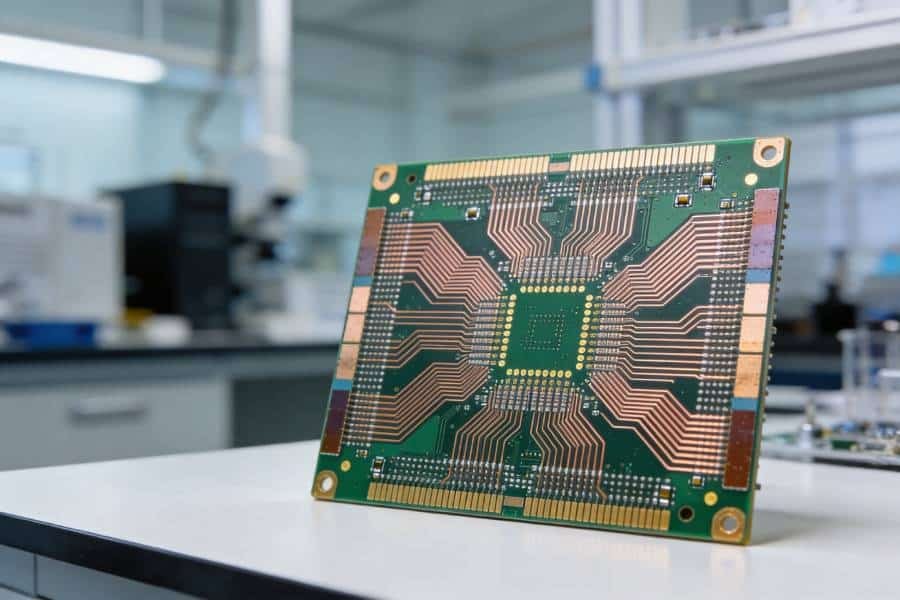
In the fast-paced world of electronics, a single oversight in PCB design can lead to catastrophic failure—like a high-voltage power supply short-circuiting in an electric vehicle due to insufficient dielectric strength. This critical property determines whether a PCB can withstand the electrical stresses of its environment, ensuring safety, reliability, and performance. At JHYPCB, a trusted China-based manufacturer of PCBs (including prototypes, single-sided, double-sided, multilayer, rigid, flexible, and rigid-flex) and assembly services (SMT, THT, mixed technology, turnkey, and component sourcing), we understand the stakes. This guide is designed to empower engineers, designers, and hobbyists with a deep understanding of PCB dielectric strength, free from promotional fluff. Here’s what we’ll cover:
- What dielectric strength is and why it’s essential
- Common PCB materials and their dielectric strengths
- Factors that impact insulation performance
- Testing methods to verify dielectric reliability
- Applications and material selection strategies
- Emerging trends in PCB materials
Whether you’re building consumer gadgets or aerospace systems, this guide will equip you with the knowledge to make informed material choices. Let’s get started!
What is Dielectric Strength in PCBs?
Dielectric strength measures a material’s ability to resist an electric field without breaking down, expressed in volts per mil (V/mil) or kilovolts per millimeter (kV/mm). In PCBs, dielectric materials—such as substrates or insulating layers between copper traces—prevent unwanted current flow, ensuring electrical isolation, signal integrity, and safety.
When dielectric strength is exceeded, the material undergoes electrical breakdown, allowing current to surge through the insulator. This can cause arcing, short circuits, or permanent damage, particularly in high-voltage applications like power supplies or medical devices. Dielectric strength is governed by standards like IPC-4101 and UL, which ensure compliance for safety and performance.
Two related properties provide context:
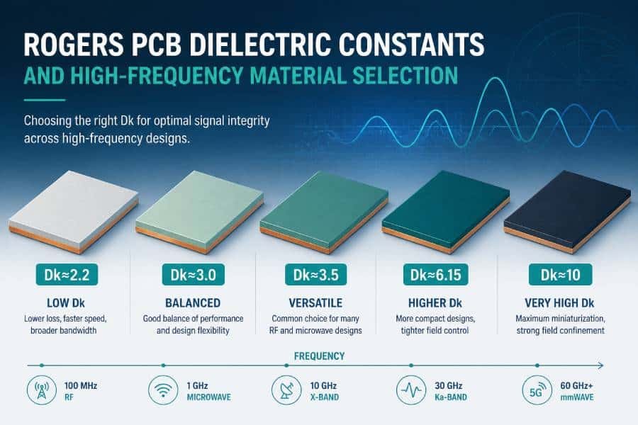
- Dielectric Constant (Dk): Measures how a material stores electrical energy, crucial for high-frequency signals.
- Dissipation Factor (Df): Indicates energy loss, affecting signal clarity in RF designs.
Breakdown occurs when the electric field overwhelms the material’s molecular structure, often exacerbated by defects like voids or contaminants. Understanding these basics helps designers avoid failures and optimize PCB performance.
Common PCB Materials and Their Dielectric Strengths
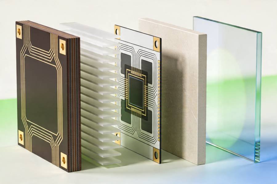
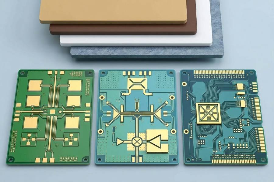
The substrate is the foundation of a PCB’s insulation, and its dielectric strength varies by material type—rigid, flexible, or specialty. Below, we explore the most common materials, their dielectric strengths, and their applications, providing a clear comparison for informed decision-making.
PTFE (Teflon-based, e.g., Rogers Materials)
- Dielectric Strength: 500–700 V/mil (20–28 kV/mm)
- Applications: RF, microwave, high-frequency circuits (e.g., 5G antennas, radar systems).
- Pros: Superior low-loss properties, excellent thermal stability, ideal for high-frequency signals.
- Cons: Higher cost makes it less viable for budget-conscious projects.
- Note: PTFE’s high dielectric strength and low Dk make it a top choice for minimizing signal loss in telecom applications.
PI (Polyimide, e.g., Kapton)
- Dielectric Strength: 300–500 V/mil (12–20 kV/mm)
- Applications: Flexible and rigid-flex PCBs in aerospace, wearables, and medical devices.
- Pros: Flexible, thermally stable up to 400°C, perfect for dynamic or compact designs.
- Cons: More expensive than standard materials but versatile for demanding environments.
- Note: Polyimide’s balance of strength and flexibility suits applications requiring repeated bending.
- Dielectric Strength: 300–500 V/mil (12–20 kV/mm)
- Applications: General-purpose electronics, consumer devices, industrial controls.
- Pros: Cost-effective, widely available, reliable for standard voltage needs.
- Cons: Susceptible to moisture absorption, limiting performance in high-humidity or extreme voltage settings.
- Note: FR-4 is the go-to for most PCBs but requires careful consideration in harsh conditions.
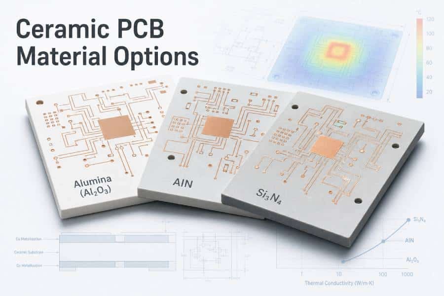
Ceramics
- Dielectric Strength: 100–200 V/mil (4–8 kV/mm)
- Applications: Automotive, aerospace, high-voltage systems (e.g., power inverters).
- Pros: Durable in extreme temperatures and harsh environments, good thermal conductivity.
- Cons: Brittle and costly, typically reserved for specialized applications.
- Note: Variants like alumina excel in rugged, high-voltage designs.
Metal-Core Dielectric
- Dielectric Strength: <100 V/mil (~4 kV/mm)
- Applications: LEDs, power electronics, thermal management systems.
- Pros: Excellent heat dissipation for high-power devices.
- Cons: Lower dielectric strength limits its use in high-voltage insulation.
- Note: Used as an insulating layer in metal-core PCBs, prioritizing thermal performance.
Copper/Aluminum
- Dielectric Strength: 0 V/mil (conductive, not dielectric)
- Applications: PCB cores, heat sinks in metal-core designs.
- Pros: Superior thermal conductivity, structural support.
- Cons: Non-insulating; requires dielectric layers for functionality.
- Note: Essential in hybrid designs but not a standalone dielectric solution.
Dielectric Strength Comparison Table
Material | Dielectric Strength (approx.) | Typical Applications | Key Properties and Notes |
|---|---|---|---|
PTFE | 500–700 V/mil (20–28 kV/mm) | RF, microwave, high-frequency circuits | Low-loss, high cost, excellent signal integrity |
PI (Polyimide) | 300–500 V/mil (12–20 kV/mm) | Flexible PCBs, aerospace, wearables | Flexible, high thermal stability |
FR-4 | 300–500 V/mil (12–20 kV/mm) | General-purpose electronics, consumer | Cost-effective, moisture-sensitive |
Ceramics | 100–200 V/mil (4–8 kV/mm) | Automotive, aerospace, high-voltage | Durable, good for harsh environments |
Metal-core dielectric | <100 V/mil (~4 kV/mm) | LEDs, power electronics | Thermal management focus, limited insulation |
Copper/Aluminum | 0 (conductive, not dielectric) | PCB cores, heat sinks | Conductive; pairs with dielectrics for hybrids |
Factors Affecting Dielectric Strength in PCB Materials
Dielectric strength isn’t solely determined by the material—several factors influence insulation performance, and understanding them is key to avoiding failures.
Material Composition
The molecular structure, resins, and fillers define a material’s intrinsic strength. For example, PTFE’s fluoropolymer chains provide exceptional insulation, while FR-4’s glass-epoxy blend is less robust in humid conditions. High-quality resins and homogeneous fillers enhance performance.
Layer Thickness
Thicker dielectric layers increase strength by extending the path electricity must travel to cause breakdown. For instance, a 1.6mm FR-4 board offers better insulation than a 0.8mm one but may add unwanted bulk. Designers must balance thickness with size, cost, and signal integrity.
Environmental Factors
- Temperature: Elevated temperatures reduce dielectric strength, especially in FR-4, which degrades above 130°C.
- Humidity: Moisture absorption, particularly in FR-4, lowers insulation effectiveness, increasing breakdown risks.
- Aging and Contaminants: Over time, pollutants, dust, or material degradation weaken insulation, leading to premature failure.
- Note: Environmental testing is critical to ensure long-term reliability in real-world conditions.
Manufacturing Variables
Defects like voids, air pockets, or improper lamination compromise dielectric strength. For example, trapped air during lamination creates weak spots prone to arcing. Techniques like vacuum lamination and Automatic Optical Inspection (AOI) help eliminate these issues, ensuring uniform insulation.
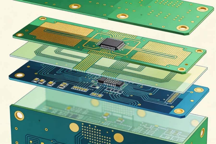
Layer Management
Effective layer management—consistent dielectric separation, strategic signal and ground plane allocation, and controlled impedance—reduces breakdown risks. Uneven layer thickness or misaligned traces can create weak points, especially in multilayer PCBs.
Dielectric Strength in Different PCB Applications
Dielectric strength requirements vary by application, and selecting the right material ensures performance and safety. Here’s how different scenarios demand specific substrates:
High-Voltage Applications
- Examples: Power supplies, electric vehicles (EVs), battery management systems (BMS).
- Requirements: High dielectric strength (e.g., ceramics or polyimide for >1kV) to prevent arcing and ensure safety.
- Example: Ceramic-based PCBs in EV power inverters, tested at 1.5 kV, provide robust insulation for high-voltage circuits.
High-Frequency and RF Designs
- Examples: 5G antennas, radar, telecom equipment.
- Requirements: Materials like PTFE with high dielectric strength and low Dk to minimize signal loss. High-frequency signals are sensitive to impurities, voids, or uneven dielectrics, which increase losses.
- Note: Plasma cleaning to remove organic residues enhances performance in RF designs.
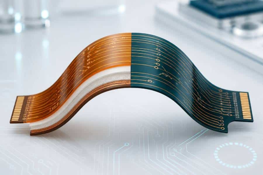
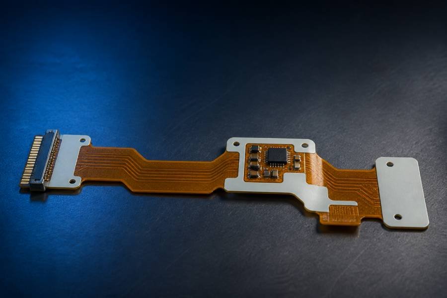
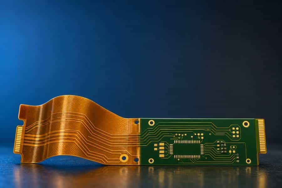
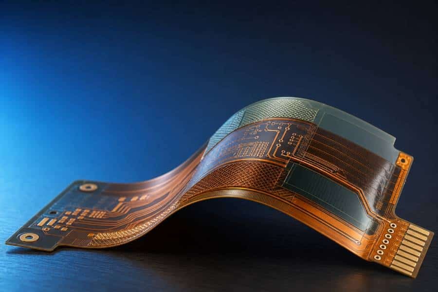
Flexible and Rigid-Flex PCBs
- Examples: Wearables, foldable electronics, aerospace sensors.
- Requirements: Polyimide for its flexibility and 300–500 V/mil strength, ideal for dynamic applications requiring repeated bending.
- Note: Proper layer alignment in rigid-flex designs ensures consistent insulation under mechanical stress.
Thermal Management
- Examples: LED lighting, power electronics.
- Requirements: Metal-core dielectrics for heat dissipation, though their lower strength (<100 V/mil) limits high-voltage use.
- Example: Metal-core PCBs for high-power LEDs, tested at 1.5 kV, balance thermal and insulation needs.
How to Select the Right PCB Material Based on Dielectric Strength
Choosing the optimal material involves balancing dielectric strength with design constraints. Follow this step-by-step guide to make informed decisions:
- Determine Voltage Needs: Identify the maximum voltage your PCB will encounter. Use ceramics or polyimide for >1kV; FR-4 for standard applications.
- Assess Operating Environment: Consider temperature, humidity, and mechanical stress. Avoid moisture-sensitive materials like FR-4 in humid settings unless treated.
- Evaluate Frequency Requirements: High-frequency designs need low-Dk materials like PTFE to reduce signal loss.
- Balance Thickness and Cost: Thicker layers enhance strength but increase size and cost. Use simulation tools or IPC-4101 specs to optimize stack-ups.
- Prototype and Test: Validate material performance with dielectric testing before scaling to production.
- Consult Standards: Reference IPC-9252 or UL guidelines for material and testing requirements.
Common Pitfalls:
- Ignoring manufacturing defects like voids, which weaken insulation.
- Overlooking environmental impacts, such as moisture absorption in FR-4.
- Selecting materials without prototyping, risking redesign costs.
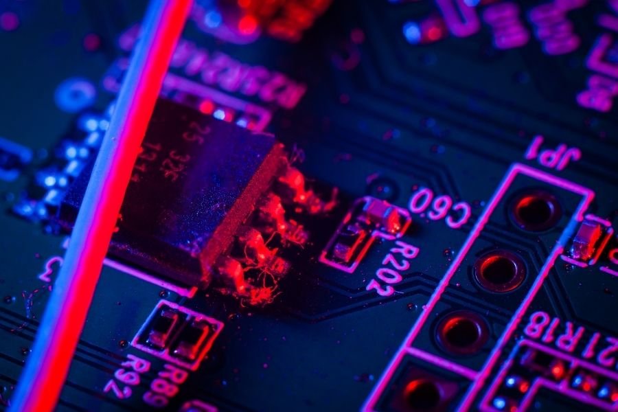
Testing Dielectric Strength in PCBs
Testing dielectric strength ensures a PCB’s insulation can withstand its intended voltage. The Dielectric Withstand Voltage (DWV) test, or HIPOT test, is the industry standard for verifying reliability.
Testing Process
- Setup: Connect a dielectric strength tester’s probes to the PCB’s contact pads or test points.
- Apply Voltage: Gradually increase voltage (e.g., up to 1.5 kV for LED PCBs) over a set duration, typically 1 minute.
- Monitor Leakage Current: Measure current flow to detect insulation weaknesses. A sudden surge indicates breakdown.
- Record Results: Note the voltage at which the material withstands or fails, ensuring compliance with design specs.
Tools and Standards
- Equipment: Dielectric testers with customizable voltage, time, and current ranges (e.g., 1.5mA to 1.0mA for high-voltage tests).
- Standards: Follow IPC-9252 for test parameters or UL for safety certification.
- Example: Testing LED PCBs at 1.5 kV for 1 minute confirms insulation at low leakage currents, ensuring reliability.
Best Practices
- Use vacuum lamination to eliminate voids.
- Perform AOI after etching to catch defects.
- Conduct environmental testing to simulate real-world conditions.
Future Trends in PCB Materials and Dielectric Strength
The PCB industry is evolving to meet the demands of advanced technologies. Emerging trends include:
- Nanocomposites: Materials with enhanced dielectric strength and lower Dk for 5G/6G applications.
- Eco-Friendly Substrates: Bio-based materials that maintain high insulation properties, aligning with sustainability goals.
- High-Frequency Materials: Advanced PTFE variants and hybrids for IoT and telecom, balancing strength and signal performance.
- Manufacturing Innovations: Techniques like laser direct structuring and plasma cleaning to improve dielectric consistency.
These advancements promise PCBs that are stronger, greener, and better suited for next-generation electronics.
Conclusion
Dielectric strength is the cornerstone of PCB reliability, ensuring insulation, safety, and performance across applications from consumer devices to high-voltage aerospace systems. By understanding materials like PTFE, polyimide, and FR-4, addressing factors like thickness and manufacturing quality, and rigorously testing dielectric performance, you can design PCBs that excel in any environment.
At JHYPCB, we specialize in delivering high-quality PCB manufacturing (prototypes, multilayer, rigid, flexible, rigid-flex) and assembly (SMT, THT, turnkey, component sourcing, SMT stencils) with a focus on precision and reliability. Certified to ISO 9001, RoHS, and UL standards, we offer free DFM support and a robust supply chain to bring your designs to life. For expert guidance or a quote on your next PCB project, contact us at sales@pcbjhy.com.
FAQs
What is the dielectric strength of FR-4 PCB material?
FR-4 offers 300–500 V/mil (12–20 kV/mm), ideal for general electronics but sensitive to moisture in high-voltage settings.
How does layer thickness affect PCB dielectric strength?
Thicker layers increase strength by lengthening the electrical path but add bulk and cost, requiring careful design balance.
What testing methods verify dielectric strength in PCBs?
Dielectric Withstand Voltage (DWV) or HIPOT tests apply high voltage to check for breakdown, monitoring leakage current.
Which material is best for high-frequency PCB dielectric performance?
PTFE (500–700 V/mil) excels due to its high strength and low dielectric constant, minimizing signal loss.
How do manufacturing defects impact dielectric breakdown?
Voids, air pockets, or contaminants weaken insulation, increasing arcing risks. Vacuum lamination and AOI mitigate these issues.
What are future trends in high-dielectric PCB substrates?
Nanocomposites, eco-friendly materials, and high-frequency substrates for 5G/6G are driving innovation.
How can environmental factors like humidity be managed in PCB design?
Choose moisture-resistant materials like PTFE or polyimide and conduct environmental testing to ensure reliability.
Why is dielectric strength critical for high-voltage PCBs?
It prevents arcing and short circuits, ensuring safety and performance in applications like EVs or power supplies.