Table of Contents
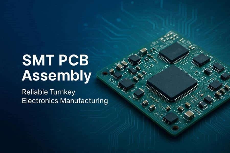
In SMT PCB assembly, quality is not judged by appearance alone. As component sizes shrink and circuit density increases, manufacturers need a clear and consistent standard to define what counts as an acceptable assembly, and that is exactly where IPC-A-610 becomes essential.
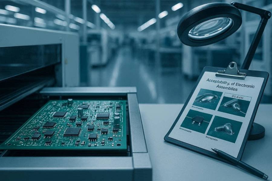
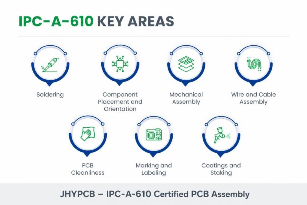
IPC-A-610 is widely recognized as the standard for acceptability of electronic assemblies, providing visual acceptance criteria for solder joints, component placement, cleanliness, and other key workmanship details.
For customers, this matters because it creates a shared definition of quality between the PCB assembler and the buyer, reducing ambiguity and helping ensure that the final product meets the expected level of reliability.
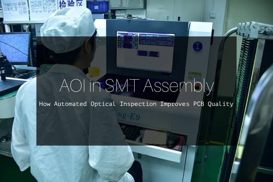
In SMT production, IPC standards also work alongside inspection tools such as AOI, X-Ray, ICT, and FCT. These testing methods find defects, while IPC-A-610 helps determine whether the observed condition is acceptable, a process indicator, or a defect.
That makes IPC compliance an important part of both quality control and customer confidence, especially for projects that demand consistency, traceability, and long-term performance.
At JHYPCB, we use IPC-based quality criteria to help guide inspection and assembly decisions across different project requirements. In this article, we will explain what IPC-A-610 is, why it matters in SMT PCB assembly, and how it supports better manufacturing outcomes for OEMs and engineering teams.
What Is IPC-A-610?
IPC-A-610 is the most widely used acceptance standard for electronic assemblies, and it defines what a finished PCB assembly should look like from a quality standpoint.
Rather than telling manufacturers how to build a board, it provides visual criteria for judging whether solder joints, component placement, cleanliness, and workmanship are acceptable.
In practical terms, IPC-A-610 acts as a shared quality language for OEMs, EMS providers, and inspectors.
That shared language matters because it reduces ambiguity during inspection, helps prevent disputes about acceptable quality, and supports more consistent production outcomes across different projects and suppliers.
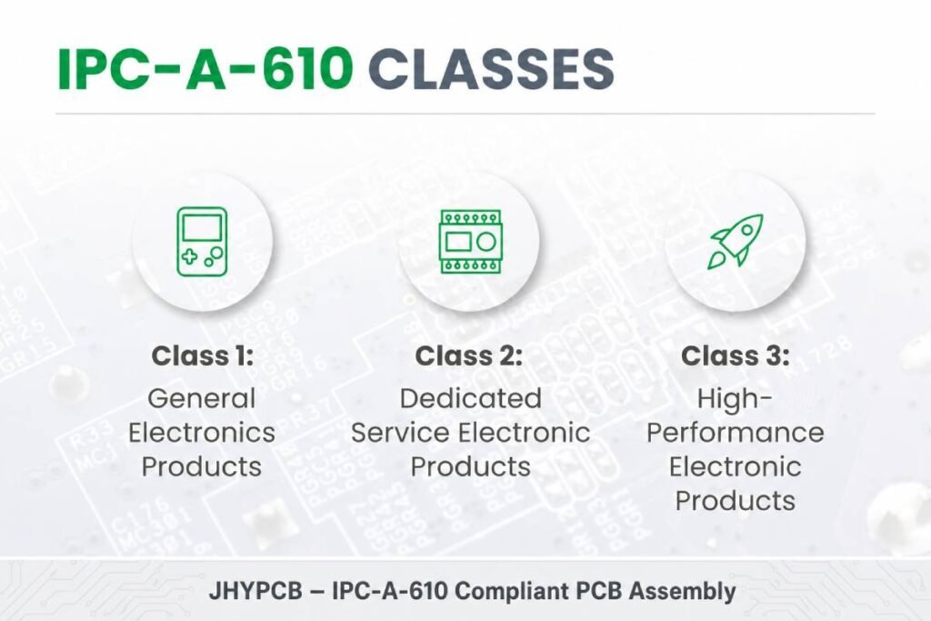
The standard is organized around three product classes: Class 1 for general electronic products, Class 2 for dedicated service products, and Class 3 for high-reliability applications.
As the class level increases, the acceptable quality threshold becomes more demanding, which is why Class 3 assemblies must meet the strictest criteria.
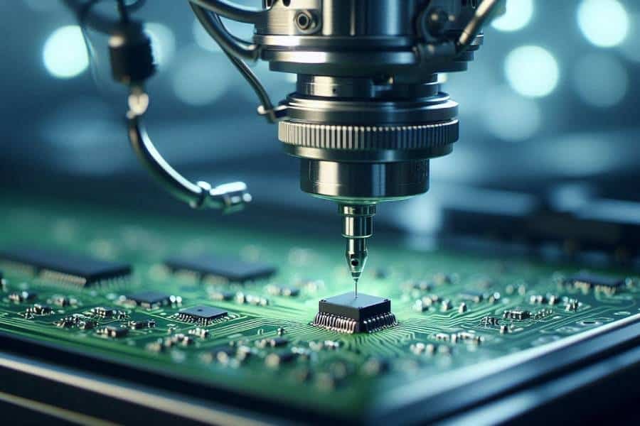
For SMT PCB assembly, IPC-A-610 is especially important because small components and dense layouts make workmanship issues harder to judge by eye alone.
The standard helps inspectors determine whether conditions such as solder bridges, insufficient wetting, component misalignment, or contamination should be treated as acceptable, process indicators, or defects.
At JHYPCB, we use IPC-A-610 as a core reference when evaluating assembly quality and setting inspection expectations for different customer requirements.
Why IPC Standards Matter in SMT PCB Assembly
IPC standards matter in SMT PCB assembly because they turn “good quality” from a vague promise into a measurable, shared requirement.
Without that common reference, one supplier’s acceptable assembly may be another supplier’s reject, which creates confusion, inconsistent outcomes, and avoidable disputes.
For SMT builds in particular, IPC standards help manufacturers manage the complexity of tiny components, dense routing, and closely spaced solder joints.
They provide clear acceptance criteria for placement, soldering, cleanliness, and workmanship, which is essential when visual judgment alone is not enough to ensure reliability.
These standards also improve repeatability across production runs.
When the same criteria are used for incoming inspection, assembly evaluation, and final acceptance, manufacturers can reduce rework, lower defect escape rates, and build more consistent products from batch to batch.
Another major reason IPC standards matter is that they support different reliability expectations through Class 1, Class 2, and Class 3 requirements.
That allows a manufacturer to match the level of inspection and workmanship to the real application, whether it is a consumer device, an industrial board, or a high-reliability system.
For customers, IPC compliance is also a trust signal.
If a PCB assembler can clearly state which IPC class they build to and how they inspect against it, buyers gain more confidence in the supplier’s process control, quality consistency, and long-term reliability.
IPC-A-610 Classes: Class 1, Class 2, and Class 3
IPC-A-610 organizes electronic assemblies into three classes based on the reliability and performance expectations of the final product.
This classification matters because the same solder joint or cosmetic condition may be acceptable in one class but rejected in another.
| IPC Class | Typical Use | Reliability Expectation | Acceptance Strictness |
|---|---|---|---|
| Class 1 | General electronic products | Basic function and limited life expectancy | Lowest |
| Class 2 | Dedicated service electronic products | Extended life and consistent performance | Medium |
| Class 3 | High-reliability electronic products | Mission-critical or harsh-environment use | Highest |
Class 1 is intended for products where the main goal is basic functionality, and occasional minor imperfections are more tolerable.
Class 2 is the most common level for many commercial and industrial assemblies, where the product must be dependable over its service life but does not require the extreme rigor of mission-critical systems.
Class 3 has the strictest requirements because failure is not acceptable in the intended application.
It is typically used for high-reliability or safety-critical electronics, where solder joint quality, cleanliness, alignment, and long-term mechanical stability must all meet the highest standard.
For SMT PCB assembly, the class you choose affects inspection depth, workmanship expectations, and final acceptance decisions.
A condition that is acceptable in Class 2 may become a defect in Class 3, which is why the required class should be defined early in the project and communicated clearly between customer and assembler.
At JHYPCB, IPC class requirements help guide how we inspect and evaluate assemblies for different end-use scenarios.
Key Acceptance Criteria in IPC-A-610 for SMT Assemblies
IPC-A-610 evaluates SMT assemblies based on whether the workmanship and soldering meet the acceptable quality level for the specified class.
In practice, that means inspectors look at the physical condition of the finished board and decide whether each feature is acceptable, only a process indicator, or a defect.
| Acceptance Area | What Inspectors Look For | Common Issues |
|---|---|---|
| Component placement | Correct orientation, alignment, and spacing | Misalignment, polarity errors, tombstoning |
| Solder joint quality | Proper wetting, fillet shape, and coverage | Cold joints, insufficient solder, bridging |
| Lead or termination condition | Secure attachment and proper contact | Lifted leads, poor termination, damaged pads |
| Cleanliness | Residue, contamination, and overall finish | Excess flux residue, debris, contamination |
| Board and component condition | Physical damage or process-related defects | Cracks, chips, scratches, lifted parts |
For SMT components, one of the most important checks is whether the part is centered on the pads and seated properly before and after reflow.
If a component is tilted, lifted, or shifted too far from its intended position, it may be treated as a defect depending on the severity and the applicable class.
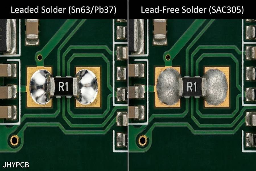
Solder joint quality is another major focus, because the joint must show proper wetting and a sound physical connection between the component and the pad.
Problems such as solder bridging, insufficient solder, cold solder joints, or poor fillet formation can all affect acceptability under IPC-A-610.
Cleanliness also matters, especially in high-reliability builds.
While some minor residue may be tolerated in lower classes, contamination, excessive flux, or debris can become an issue when the assembly must meet tighter workmanship expectations.
For mixed-technology boards, inspectors apply the appropriate criteria to both SMT and through-hole features.
That makes IPC-A-610 useful not only for evaluating the board as a whole, but also for creating a consistent inspection standard across different component types and product classes.
How IPC-A-610 Supports Inspection and Quality Control
IPC-A-610 supports inspection and quality control by giving manufacturers a clear benchmark for judging whether an assembly is acceptable.
Instead of relying on subjective opinions, inspectors can compare the finished board against defined criteria for placement, soldering, cleanliness, and workmanship.
This becomes especially important when IPC-A-610 is paired with inspection tools such as AOI and X-Ray.
Those tools help detect or highlight possible issues, while IPC-A-610 helps quality teams decide whether the condition should be accepted, reviewed further, or rejected based on the applicable class.
In real production workflows, IPC-A-610 also improves consistency across operators and shifts.
When everyone uses the same acceptance criteria, the risk of uneven inspection decisions drops, which helps reduce rework, improve yield, and make quality control more repeatable.
The standard is also valuable for process improvement.
If the same defect starts appearing repeatedly—such as misalignment, weak wetting, or residue-related issues—the IPC framework gives engineers a common language for tracking the problem back to soldering, placement, cleaning, or handling processes.
For high-reliability builds, IPC-A-610 becomes more than an inspection reference; it becomes part of the overall quality assurance system.
That is why many manufacturers and OEMs use it alongside process standards and test methods to strengthen final acceptance and customer confidence.
IPC-A-610 vs. J-STD-001: What’s the Difference?
IPC-A-610 and J-STD-001 are closely related, but they serve different purposes in PCB assembly.
The simplest way to understand the difference is this: IPC-A-610 defines what an acceptable finished assembly looks like, while J-STD-001 defines how the soldered assembly should be built.
IPC-A-610 is primarily an inspection and acceptability standard.
It is used by inspectors, QA teams, and customers to judge the appearance and condition of the final product against visual acceptance criteria.
J-STD-001, on the other hand, focuses on soldering requirements, process control, materials, and workmanship during production.
It is the document that tells manufacturers how to create reliable solder joints and maintain a sound assembly process before the board reaches final inspection.
You can think of them as two sides of the same quality system.
J-STD-001 sets the manufacturing rules, and IPC-A-610 checks whether the finished board meets the expected outcome.
For SMT PCB assembly, both standards are useful because one supports process consistency and the other supports final acceptance.
When used together, they create a more complete quality framework for building and verifying reliable electronics.
When Should You Specify IPC Class Requirements?
You should specify the IPC class requirement as early as possible, ideally during the quotation, design review, or procurement stage.
If the class is not defined clearly at the beginning, the assembler and the customer may end up judging the same board against different quality expectations.
For most commercial and industrial products, Class 2 is the most common choice because it balances reliability and cost.
If the product must perform consistently over a long service life but is not mission-critical, Class 2 is often the most practical and economical requirement.
Class 3 should be specified when failure is unacceptable or extremely costly.
This is typically the right choice for medical, aerospace, defense, high-end industrial, or safety-related electronics where reliability, cleanliness, solder quality, and inspection rigor must be at the highest level.
Class 1 is generally suitable only for simple consumer products where basic function is the main goal and long-term reliability demands are low.
In those cases, stricter requirements would add unnecessary cost without providing meaningful value to the end user.
A useful rule is to match the class to the product’s real risk, environment, and service expectation.
When the application involves heat, vibration, safety, or expensive field failure, it is usually better to define the higher class upfront rather than try to upgrade acceptance later.
At JHYPCB, specifying the right IPC class helps us align inspection depth and workmanship expectations with the actual end-use of the assembly.
How JHYPCB Applies IPC Standards in SMT PCB Assembly
At JHYPCB, IPC standards are built into the way we evaluate every SMT PCB assembly job, from incoming material checks to final inspection.
Rather than treating IPC-A-610 as a reference we look at only at the end, we use it as part of our day-to-day quality control framework so the build outcome stays aligned with the required class and customer expectations.
Our process begins with defining the target IPC class for the project, because Class 1, Class 2, and Class 3 all require different acceptance thresholds.
That early decision helps us set the right inspection depth, workmanship expectations, and documentation level before production starts.
During assembly, we combine IPC-based workmanship criteria with the appropriate inspection methods for the product.
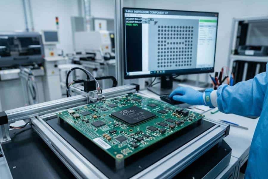
For visible defects, AOI helps us verify placement and solder quality, while X-Ray is used when hidden solder joints or BGA-style packages require deeper inspection.
If the project requires higher confidence in electrical or functional performance, we also support ICT and FCT as part of the broader quality plan.
That means IPC standards do not stand alone in our workflow; they are paired with practical test methods so the assembly is checked both for workmanship and for real-world performance.
We also use IPC criteria to support traceability and continuous improvement.
When a defect appears repeatedly, the standard gives our team a consistent way to classify the issue, investigate the root cause, and adjust the process to prevent recurrence.
For our customers, this approach creates a more transparent and predictable quality system.
It means you are not just buying PCB assembly—you are getting a manufacturing partner that builds and inspects according to internationally recognized acceptance standards.
Partner with JHYPCB for Reliable IPC-Compliant PCB Assembly
At JHYPCB, IPC compliance is not treated as a final checkbox—it is embedded in how we build, inspect, and deliver every SMT PCB assembly job.
From incoming material checks to final acceptance, we use IPC-based criteria to keep quality consistent and to make sure each board meets the expectations of its target class.
For customers, this means fewer surprises and more predictable results.
When the project requires Class 2 or Class 3 workmanship, we align our inspection depth, process control, and documentation with the reliability level the application actually demands.
We also combine IPC standards with the right inspection and test methods so quality is verified from multiple angles.
AOI helps us check placement and visible solder quality, X-Ray helps us evaluate hidden joints, and electrical or functional testing adds another layer of confidence before shipment.
This integrated approach is especially valuable for complex SMT builds, high-density assemblies, and applications where long-term reliability matters more than basic pass/fail inspection.
By using IPC standards as a common language across production and inspection, JHYPCB helps reduce rework, improve repeatability, and support stronger customer trust.
If you are looking for an SMT PCB assembly partner that builds with IPC compliance in mind, JHYPCB can help you match the right standard, the right inspection method, and the right quality target to your project.
That way, your boards are not only assembled correctly, but also evaluated against a recognized quality benchmark before they leave the factory.