Table of Contents
What is SMT Reflow Soldering?
SMT (Surface Mount Technology) reflow soldering is a critical process in PCB assembly, enabling high-density electronic component placement with superior electrical performance. Unlike traditional through-hole assembly, SMT uses automated processes to solder surface-mount components onto PCBs, meeting the demands of modern electronics for efficiency and precision.
The reflow soldering process determines the quality of solder joints, as defects from solder paste printing, component placement, or PCB design converge here. Optimizing the reflow temperature curve is crucial to prevent issues such as component cracking, warpage, bridging, or PCB delamination.
How Reflow Ovens Work
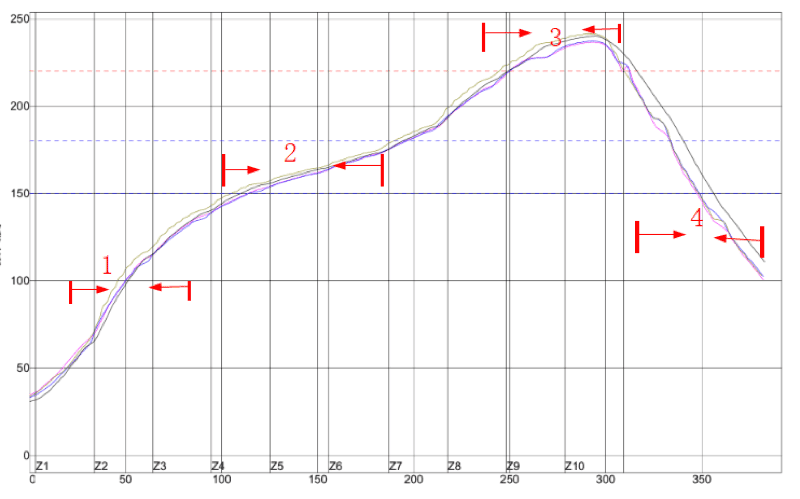
Reflow ovens heat PCBs and components through four temperature zones: preheating, insulation, reflow, and cooling. Each zone plays a specific role in ensuring high-quality solder joints.
1. Preheating Zone: Controlled Temperature Rise
The preheating zone raises the PCB temperature from ambient to 120–160°C at a rate of 1–3°C/sec to activate flux and prevent thermal shock. A heating rate exceeding 4°C/sec risks damaging components or PCBs, while a slower rate may reduce flux effectiveness, leading to poor soldering quality.
2. Insulation Zone: Achieving Temperature Uniformity
- Purpose: Stabilizes PCB temperature between 120°C and 160°C.
- Goal: Minimizes temperature gradients across components.
- Duration: 60–100 seconds to ensure flux activation and oxide removal from pads and pins.
Uniform temperatures in this zone prevent defects like bridging or cold soldering by ensuring all components reach equilibrium before entering the reflow zone.
3. Reflow Zone: Reaching Peak Soldering Temperature
The reflow zone heats components to a peak temperature of 210–230°C for Sn/Pb solder paste (melting point: 183°C) or 235–250°C for lead-free solder paste (e.g., SAC305, melting point: ~217°C). The duration at peak temperature (20–30 seconds) ensures proper solder joint formation without damaging the PCB.
Note: Prolonged exposure above 200°C can cause PCB blistering or component warpage. Adjust reflow time based on solder paste specifications.
4. Cooling Zone: Solidifying Solder Joints
The cooling zone rapidly cools molten solder at 3–10°C/sec to form bright, strong solder joints with low contact angles. Slow cooling may lead to dull, rough joints or weak bonding due to flux decomposition. Forced cooling with ion fans is commonly used to achieve optimal results.
Two SMT Reflow Soldering Temperature Curve Modes
The two primary reflow temperature curve modes—Warm-Up Keep Warm and Gradual Heating—offer distinct approaches to achieving high-quality solder joints. Below, we compare their characteristics, advantages, and challenges.
Warm-Up Keep Warm Mode
This traditional mode involves:
- Rapid heating (1–3°C/sec) to a preheating temperature of 140–170°C (±10°C).
- Maintaining this temperature for 40–120 seconds to activate flux.
- Quick transition to the reflow zone (210–230°C).
- Rapid cooling at ≤4°C/sec.
Pros: Lower preheating temperatures reduce thermal stress on components.
Cons: Rapid temperature transitions can disrupt solder rheology, causing displacement or bridging. Flux activation is less effective at lower temperatures.
Gradual Heating Mode
This modern mode, considered optimal for many applications, involves:
- Slow heating (0.5–1°C/sec) to ~175°C.
- Gradient rise to ~180°C over 20–30 seconds.
- Rapid rise (2.5–3.5°C/sec) to ~220°C (or 235–250°C for lead-free).
- Cooling at ≤4°C/sec.
Pros: Higher flux activation temperatures and gradual heating reduce defects like warpage and cold soldering.
Cons: Higher preheating temperatures increase thermal exposure, requiring precise control.
Warm-Up Keep Warm vs. Gradual Heating: A Comparison
| Feature | Warm-Up Keep Warm Mode | Gradual Heating Mode |
|---|---|---|
| Preheating Rate | 1–3°C/sec to 140–170°C | 0.5–1°C/sec to 175°C |
| Insulation Duration | 40–120 seconds | 20–30 seconds |
| Peak Temperature | 210–230°C | ~220°C (or 235–250°C) |
| Pros | Less thermal stress on components | Better flux activation, fewer defects |
| Cons | Risk of soldering rheology issues | Higher thermal exposure |
Tips for Optimizing Your Reflow Oven Settings
To achieve the best results in SMT reflow soldering, consider these practical tips:
- Calibrate Regularly: Monitor and adjust reflow oven temperatures to maintain specified rates (e.g., 1–3°C/sec in preheating).
- Test Solder Paste: Use manufacturer-recommended peak temperatures (e.g., 235–250°C for SAC305 lead-free paste).
- Monitor Cooling: Ensure cooling rates of 3–10°C/sec to form strong solder joints.
- Profile PCBs: Use thermal profiling tools to verify temperature uniformity across the PCB.
Frequently Asked Questions About SMT Reflow Soldering
What is the ideal reflow soldering temperature for lead-free solder paste?
For lead-free solder paste like SAC305 (melting point: ~217°C), aim for a peak temperature of 235–250°C for 20–30 seconds.
How do I prevent thermal shock in the preheating zone?
Maintain a heating rate of 1–3°C/sec and ensure uniform PCB heating using thermal profiling tools.
What causes bridging in reflow soldering?
Bridging results from uneven heating or excessive solder paste. Optimize the insulation zone (60–100 seconds) and check solder paste application.
Conclusion
Optimizing your SMT reflow soldering temperature curve—whether using Warm-Up Keep Warm or Gradual Heating mode—is key to achieving high-quality PCB assembly. By carefully controlling preheating, insulation, reflow, and cooling zones, you can minimize defects like warpage, bridging, and cold soldering. Experiment with both modes and use thermal profiling to find the best settings for your reflow oven and solder paste.