Table of Contents
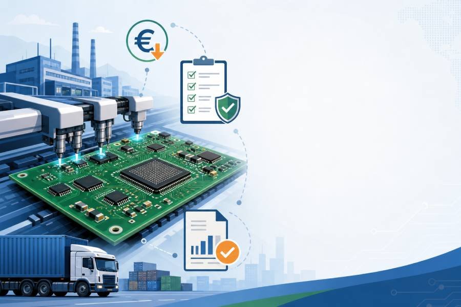
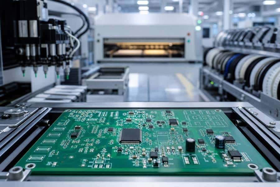
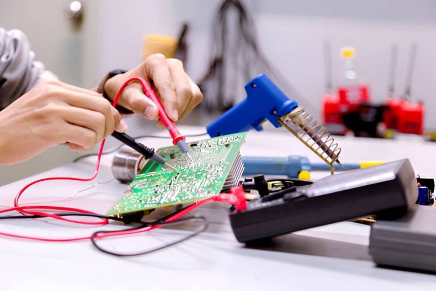
As a seasoned PCB manufacturer and assembly expert at JHYPCB, we’ve seen countless projects where precise component testing makes all the difference between a flawless circuit and a frustrating failure. In our years of providing high-quality PCB fabrication services—including prototypes, multilayer boards, rigid-flex designs—and comprehensive PCB assembly like SMT, THT, and turnkey solutions, we’ve honed our diagnostics processes to ensure every board we produce meets the highest standards. But what if you’re handling repairs or validations in-house? That’s where mastering how to check PCB components with a multimeter comes in handy.
This guide isn’t just a basic rundown; it’s an advanced, value-packed resource designed to elevate your skills. We’ll dive deeper than standard tutorials, incorporating real-world insights from our engineering team, common pitfalls we’ve encountered in production, and pro tips for optimizing your testing workflow. Whether you’re a DIY enthusiast debugging a hobby project or a professional engineer ensuring quality in PCB assembly, understanding multimeter testing for PCB components will save you time, reduce waste, and boost reliability. Let’s explore how to test PCB components with a multimeter step by step, focusing on accuracy, safety, and efficiency.
Why Multimeter Testing is Crucial in PCB Diagnostics
In the world of electronics, a multimeter is your go-to tool for non-destructive testing. It measures key electrical properties like resistance, voltage, current, continuity, and diode functionality, helping you pinpoint issues without dismantling the entire board. At JHYPCB, we integrate multimeter checks into our quality assurance during PCB assembly to catch defects early—such as faulty resistors in SMT placements or shorted diodes in high-density designs.
Unlike more complex tools like oscilloscopes, a multimeter is affordable, portable, and versatile for both in-circuit and out-of-circuit testing. Key benefits include:
- Early Fault Detection: Identify open circuits, shorts, or value drifts before they cause system failures.
- Cost Savings: Avoid unnecessary component replacements by verifying functionality.
- Enhanced Troubleshooting: Ideal for long-tail scenarios like “how to check PCB components with multimeter for intermittent faults” or “multimeter testing PCB capacitors in flexible boards.”
Common components testable with a multimeter include resistors, capacitors, diodes, transistors, fuses, inductors, and even traces for continuity. However, for multilayer or rigid-flex PCBs, accessibility can be tricky—pro tip: use our schematic reviews during fabrication to map out test points in advance.
Essential Tools and Preparation for PCB Component Testing
Before diving into how to test PCB components using a multimeter, gather the right gear. Based on our assembly line experience, here’s what you’ll need:
- Digital Multimeter (DMM): Opt for one with auto-ranging, continuity buzzer, diode mode, capacitance, and transistor testing. We recommend models like the Fluke 117 for precision in professional settings.
- Test Probes and Clips: Alligator clips for hands-free testing, especially on populated boards.
- Magnifying Tools: A loupe or digital microscope to read tiny SMD component markings.
- Desoldering Kit: Pump, wick, or iron for isolating components in dense assemblies.
- ESD Protection: Wrist straps and mats to prevent static damage—critical in our SMT processes.
- Schematics and Datasheets: Reference these for expected values; at JHYPCB, we provide detailed docs with every order.
Preparation steps to ensure safe, accurate results:
- Power Down and Discharge: Always unplug the board and discharge capacitors with a resistor (e.g., 1kΩ) to avoid shocks or false readings.
- Isolate if Needed: For in-circuit testing pitfalls, lift one leg of the component—common in our THT assembly inspections.
- Calibrate Your Multimeter: Test on known values first to confirm accuracy.
- Environment Check: Work in a well-lit, static-free area to mimic our controlled fabrication facilities.
By preparing thoroughly, you’ll avoid common errors like “multimeter not reading PCB resistor correctly due to parallel paths.”

Step-by-Step: How to Test Specific PCB Components with a Multimeter
Let’s break down the testing process component by component, with advanced techniques drawn from our expertise in PCB manufacturing and assembly.
1. Testing Resistors on PCBs
Resistors are foundational in circuits, and faulty ones can disrupt voltage dividers or current limits. For “how to check resistor on PCB with multimeter,” follow these steps:
- Set to resistance (Ω) mode, starting with the highest range for unknowns.
- Probe both ends; polarity doesn’t matter.
- Compare to the color code or SMD marking (e.g., 103 for 10kΩ).
- Pro Tip: In-circuit? Account for tolerances (±5-10%) and parallel resistances. If off, desolder and retest. We’ve seen heat-damaged resistors in over-soldered assemblies—check for discoloration too.
Expected: Matches nominal value. Faulty if infinite (open) or zero (short).
2. Testing Capacitors for Reliability
Capacitors store charge and filter signals, but they degrade over time. Search terms like “how to test capacitor on PCB with multimeter” often lead here:
- Use capacitance mode if available; otherwise, resistance for basic checks.
- Discharge first, then probe with red on positive (for polarized caps) and black on negative.
- Watch for initial low resistance rising to infinite (charging effect).
- Advanced: For electrolytic caps in power supplies, check ESR (Equivalent Series Resistance) with specialized modes—high ESR indicates failure, common in aged boards.
In our PCB assembly, we test caps post-SMT to ensure no leaks. Faulty signs: Bulging or no charging curve.
3. Diode Testing for Forward Bias and Protection
Diodes direct current flow, vital in rectification. To master “how to check diode on PCB with multimeter”:
- Switch to diode mode (symbol: arrow with line).
- Red probe to anode, black to cathode: Expect 0.5-0.8V drop (silicon) or 0.2-0.3V (Schottky).
- Reverse: Should read OL (open loop).
- Tip: Zero in both directions? Shorted. OL both ways? Open. Test in-circuit carefully, as parallel diodes can skew results—seen in our LED array assemblies.
4. Transistor Verification in Amplifiers and Switches
Transistors amplify or switch signals. For “how to test transistor on PCB with multimeter”:
- Diode mode for junction checks.
- For NPN: Base (+) to Emitter (-): ~0.6V; Base to Collector: ~0.6V. Reverse: OL.
- PNP: Swap probe polarities.
- HFE Mode (if available): Insert into multimeter socket for gain measurement.
- Expert Insight: In high-power apps like motor drivers, check for thermal runaway. We use this in our turnkey assemblies to validate BJTs and MOSFETs.
5. Additional Tests: Fuses, Inductors, and Continuity
- Fuses/Jumpers: Continuity mode—beep for good, OL for blown.
- Inductors: Resistance mode for coil continuity (low Ω); advanced LCR meters for inductance.
- Board Traces: Probe for continuity to detect cracks, especially in flexible PCBs we manufacture.

Common Mistakes and Troubleshooting Insights
From our experience troubleshooting client boards, avoid these:
- Testing powered circuits: Risks meter damage—always de-energize.
- Ignoring Polarity: Leads to inverted readings in diodes/caps.
- Inaccurate In-Circuit Tests: Parallel components fool readings; isolate for precision.
- Overlooking Environmental Factors: Humidity can affect caps; test in controlled conditions.
Interpreting Results:
- OL/No Reading: Open circuit—check solder joints.
- Zero/Short: Inspect for bridges, common in SMT.
- Fluctuating Values: Loose connections or failing probes.
If issues persist, consult our component sourcing team for replacements.
Safety Best Practices for Multimeter Use in PCB Testing
Safety first—our mantra at JHYPCB:
- Never probe live high-voltage areas without proper insulation.
- Discharge all energy storage components.
- Use CAT-rated multimeters for industrial voltages.
- Wear PPE and work ESD-safe to protect sensitive ICs.
FAQs: Answering Your PCB Testing Queries
Can I test SMD components without desoldering?
Yes, but for accuracy in dense boards, use fine probes or isolate. Our SMT stencils ensure clean placements for easier access.
What's the best multimeter for PCB work?
Auto-ranging DMMs with capacitance and transistor modes. For pros, invest in benchtop models.
How do I handle "multimeter showing wrong value on PCB capacitor"?
Discharge fully and retest; if persistent, it might be leaky—replace with our sourced parts.
Is multimeter testing enough for complex PCBs?
It’s a great start, but pair with oscilloscopes for dynamic issues in multilayer designs.
Wrapping Up: Elevate Your PCB Skills with Expert Testing
Mastering how to check PCB components with a multimeter empowers you to maintain peak performance in your electronics. At JHYPCB, we apply these principles daily in our PCB manufacturing and assembly services, from prototyping to full turnkey production. Whether you’re dealing with rigid, flexible, or rigid-flex PCBs, accurate diagnostics ensure longevity and reliability.
Ready to tackle your next project? Contact us at sales@pcbjhy.com for a free quote on PCB fabrication, assembly, or component sourcing. Our team is here to support your success with top-tier expertise and quality you can trust. Let’s build something exceptional together!